

Page 1
VisuNet GXP
RM-GXP1100 and
RM-GXP1200
System Manual
PROCESS AUTOMATION
MANUAL
Page 2

With regard to the supply of products, the current issue of the following document is ap-
plicable: The General Terms of Delivery for Products and Services of the Electrical Indus-
try, published by the Central Association of the Electrical Industry (Zentralverband
Elektrotechnik und Elektroindustrie (ZVEI) e.V.) in its most recent version as well as the
supplementary clause: "Expanded reservation of proprietorship"
VisuNet GXP RM-GXP1100 and RM-GXP1200
Page 3

VisuNet GXP RM-GXP1100 and RM-GXP1200
3
1 Introduction................................................................................. 4
1.1 Content of this Document ................................................................... 4
1.2 Target Group, Personnel...................................................................... 4
1.3 Symbols Used ...................................................................................... 4
2 Product Description ................................................................... 6
2.1 Overview ............................................................................................... 6
2.2 Technical Specifications...................................................................... 8
2.3 Dimensions......................................................................................... 10
2.4 Scope of Delivery............................................................................... 10
3 Mechanical Installation ............................................................ 11
3.1 Unpacking........................................................................................... 11
3.2 System Installation............................................................................. 13
3.2.1 Preparing the Pedestal..................................................................... 13
3.2.2 Mounting the Housing...................................................................... 13
3.2.3 Closing the Housing......................................................................... 16
3.2.4 Mounting the Keyboard.................................................................... 18
3.2.5 Mounting the Scanner Holder to the Housing .................................. 19
3.2.6 Installing the Scanner Cable ............................................................ 21
3.2.7 Dismounting the Display Unit ........................................................... 22
3.3 Panel Mount Installation .................................................................... 25
4 Electrical Installation................................................................ 29
4.1 Grounding the Housing to the Pedestal .......................................... 30
4.2 Grounding the Housing to the Wall-Bracket.................................... 31
5 Appendix ................................................................................... 32
5.1 Accessories ........................................................................................ 32
Page 4
302041 2017 -05
4
VisuNet GXP RM-GXP1100 and RM-GXP1200
Introduction
1 Introduction
1.1 Content of this Document
This document contains information that you need in order to use your product throughou t the
applicable stages of the produ ct life cycle. These can include the following:
■
Product identification
■
Delivery, transport, and storage
■
Mounting and installation
■
Commissioning and operation
■
Maintenance and repair
■
Troubleshooting
■
Dism ounting
■
Disposal
The docum entation consists of the following parts:
■
Present document
■
Instruction manual
■
Datasheet
Additionally, the following parts m ay belong to the documentation, if applicable:
■
EU-type examination certificate
■
EU declaration of conformity
■
Attestation of conformity
■
Certificates
■
Control drawings
■
Additional docum ents
1.2 Target Group, Personnel
Responsibility for planning, assembly, commissioning, operation, maintenance, and
dismounting lies with the plant operator.
Only appropriately trained and qualified personnel may carry out m ounting, installation,
commissioning, operation, maintenance, and dismounting of the product. The personnel must
have read and understood the instruction manual and the further docu mentation.
Prior to using the produ ct make yourself familiar w ith it. Read the document carefully.
Note!
This document does not substitute the instruction manual.
Note!
For full information on the product, refer to the instruction manu al and further documentation on
the Internet at www.pepperl-fuchs.com.
Page 5
VisuNet GXP RM-GXP1100 and RM-GXP1200
Introduction
302041 2017 -05
5
1.3 Symbols Used
This document contains symbols for the identification of warning messages and of informative
messages.
Warning Messages
You will find warning messages, whenever dangers may arise from your actions. It is mandator y
that you observe these warning messages for your personal safety and in order to avoid
property damage.
Depending on the risk level, the warning messages are displayed in descending order as
follows:
Informative Symbols
Action
This symbol indicates a paragraph with instructions. You are prompted to perform an action or
a sequence of actions.
Danger!
This symbol indicates an imminent danger.
Non-observance will result in personal injury or death.
Warning!
This symbol indicates a possible fault or danger.
Non-observance may cause persona l injury or serious property damage.
Caution!
This symbol indicates a possible fault.
Non-observance could interrupt the device and any connected systems and plants, or result in
their complete failure.
Note!
This symbol brings important information to your attention.
Page 6
302041 2017 -05
6
VisuNet GXP RM-GXP1100 and RM-GXP1200
Product Description
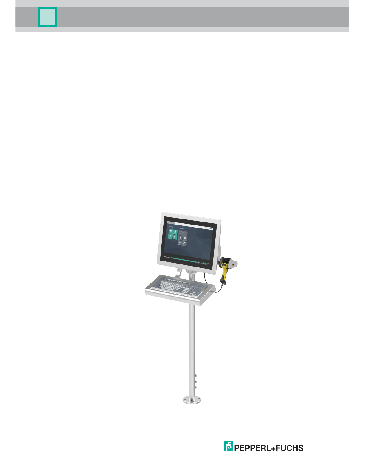
2 Product Description
2.1 Overview
The Pepperl+Fuchs VisuNet Remote Monitors GXP RM-GXP1100-* and RM-GXP1200-* are
explosion-protected apparatuses certified for use in hazardous areas rated according to IECEx
& ATEX Zone 1/21 and Zone 2/22 type designations.
The VisuNet GXP serves as a thin-client based operator workstation that uses standard
Ethernet technology to transmit process information from a process control or manufacturing
execution system into hazardous areas.
The assembly consists of three core devices which can be replaced by the customer:
■
The display units DPU1100-* and DP U1200-* are display panels with optionally available
10-finger m ulti-touch sensors, rated for zones 1/21 and 2/22, respectively. The displays
and touch-sensors are optically bonded with the hardened front glass.
■
The thin client units TCU1100-* and TCU1200-* are computing units running the latest
Pepperl+Fuchs RM shell 4.x firmware. They allow connecting to various sets of host
systems in the safe are, using standard Ethernet technology.
■
The power supply units PSU1100-* and PSU1200-* provide the above mentioned devices
with 24 V DC power. They are available as DC and as wide-range AC versions.
As the standard mounting option, a bezel is avaible which allows mounting the panel into a
system housing or cabinet (mounting kit required). The panel can also be flush-mounted into a
cabinet from behind, using additionally available mounting brackets.
Page 7

VisuNet GXP RM-GXP1100 and RM-GXP1200
Product Description
302041 2017 -05
7
2.2 Technical Specifications
Technical Data
Hardware
Processor Intel® Atom™ Bay Trail E3827 1.75 GHz
RAM 2 GB DDR3L
Mass storage 32 GByte industrial grade MLC SSD
Supply
Power consumption max . 72 W , typ. 55 W
Interface
Interface type 1 x Ethernet 100/1000BASE-T 1000 MBit/s (Ex e) or fiber optic
1000Base-SX, 1000 MBit/s
1x USB 2.0 (Ex e)
2x USB 1.1 (Ex i; intended for P+F keyboard and mouse)
optional: 1x barcode reader interface P+F Pscan-D/B (Ex i)
1x DC or AC power in (via power supply unit)
Software
Operating system VisuNet RM Shell 4.x (based on Microsoft Windows
Embedded Standard 7)
Supports Microsoft DRDP, VNC, and other remote desktop
protocols
Ambient conditions
Operating temperature 0 ... 50 °C (32 ... 122 °F) (norm al operation) ;
-20 ... 50 °C (-4 ... 122 °F) (after 1 hour of operation)
Storage temperature -20 ... 60 °C (-4 ... 140 °F)
Relative h umidity 93% at 40°C, non-condensating, according to EN60068-2-78
Vibration resistance 10 ... 150 Hz, +/- 0.075 mm , 1g, 10 cycles per axis according
to EN 60068-2-6
Mechanical specifications
Degree of protection IP66 (panel with system housing)
Material Panel: anodized aluminum (TCU, PSU), powder coated
aluminum (DPU)
Bezel: stainless steel AISI 304 (1.4301)
System housing: s tainless steel AISI 304 (1.4301), ceramic
blasted
Page 8
302041 2017 -05
8
VisuNet GXP RM-GXP1100 and RM-GXP1200
Product Description
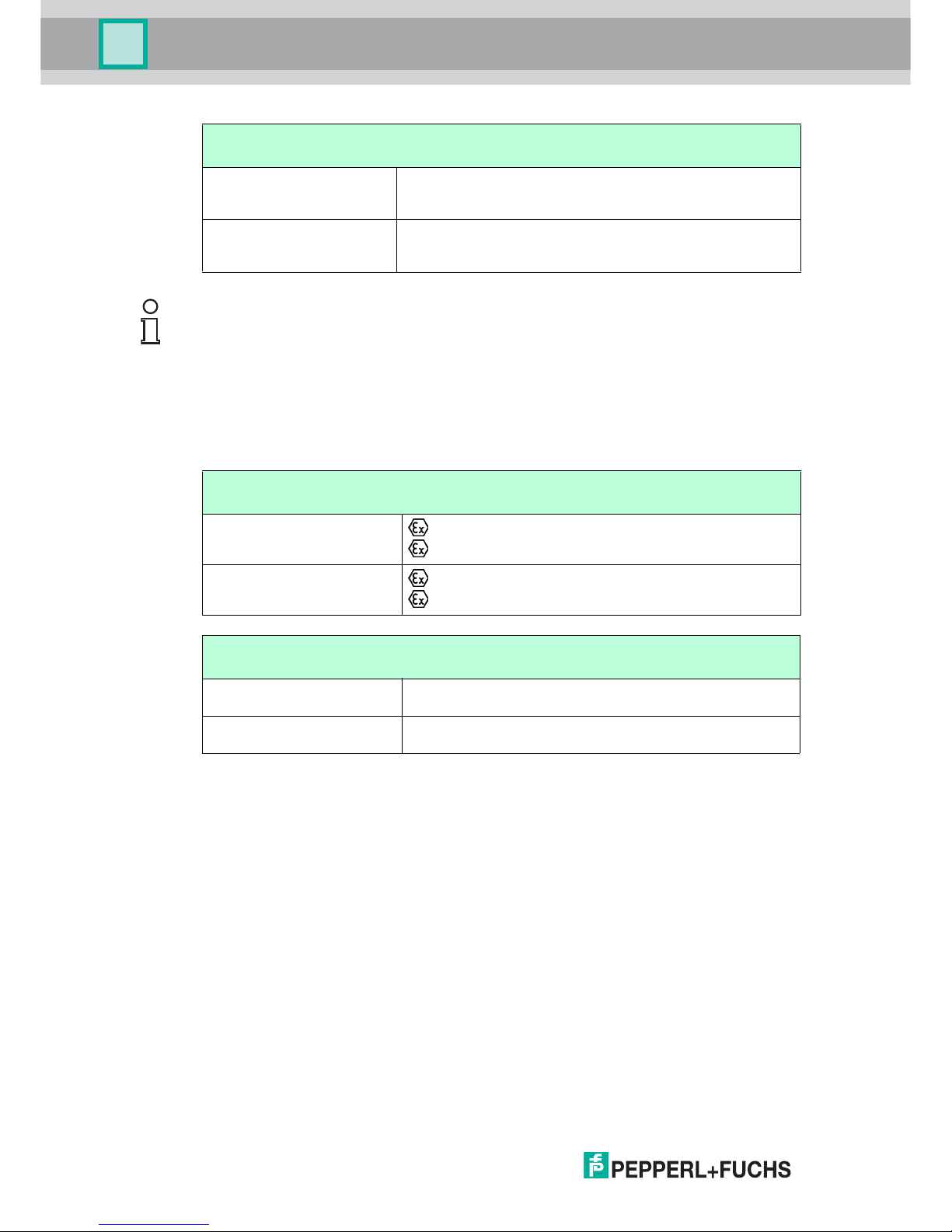
Marking
Mass Panel (DPU with bezel, TCU, PSU DC): approx. 17.5 kg
Panel (DPU with bezel, TCU, PSU AC): approx. 18 kg
System housing: approx. 11 kg
Dimensions Panel (DPU with bezel, TCU, PSU DC): 625x459x120 mm
Panel (DPU with bezel, TCU, PSU AC): 625x459x137 mm
Panel with system housing: 625x459x173 mm
Mechanical specifications
Note!
For more technical information, please refer to the datasheets of the individual components:
■
Display Units DPU1100-J1* and DPU1200-J2*
■
AC Power Supply Units PSU1100-J1-AC-N0 and PSU1200-J2-AC-N0
■
DC Power Supply Units PSU1100-J1-DC-N0 and PSU1200-J2-DC-N 0
■
Thin Client Units TCU1100-J1-* and TCU1200-J2-*
ATEX
RM-GXP1100-J1-*
II 2G Ex eb q ib [ib] IIC T4 IP66 Gb
II 2D Ex tb [ib] IIIC T85°C IP66 Db
RM-GXP1200-J2-*
II 3G Ex ec [ib] q IIC T4 IP66 Gc
II 3D Ex tc [ib] IIIC T85 °C IP66 Dc
IECEx
RM-GXP1100-J1-* Ex eb q ib [ib] IIC T4 IP66 Gb
Ex tb [ib] IIIC T85°C IP66 Db
RM-GXP1200-J2-* Ex ec [ib] q IIC T4 IP66 Gc
Ex tc [ib] IIIC T85 °C IP66 Dc
Page 9
VisuNet GXP RM-GXP1100 and RM-GXP1200
Product Description
302041 2017 -05
9
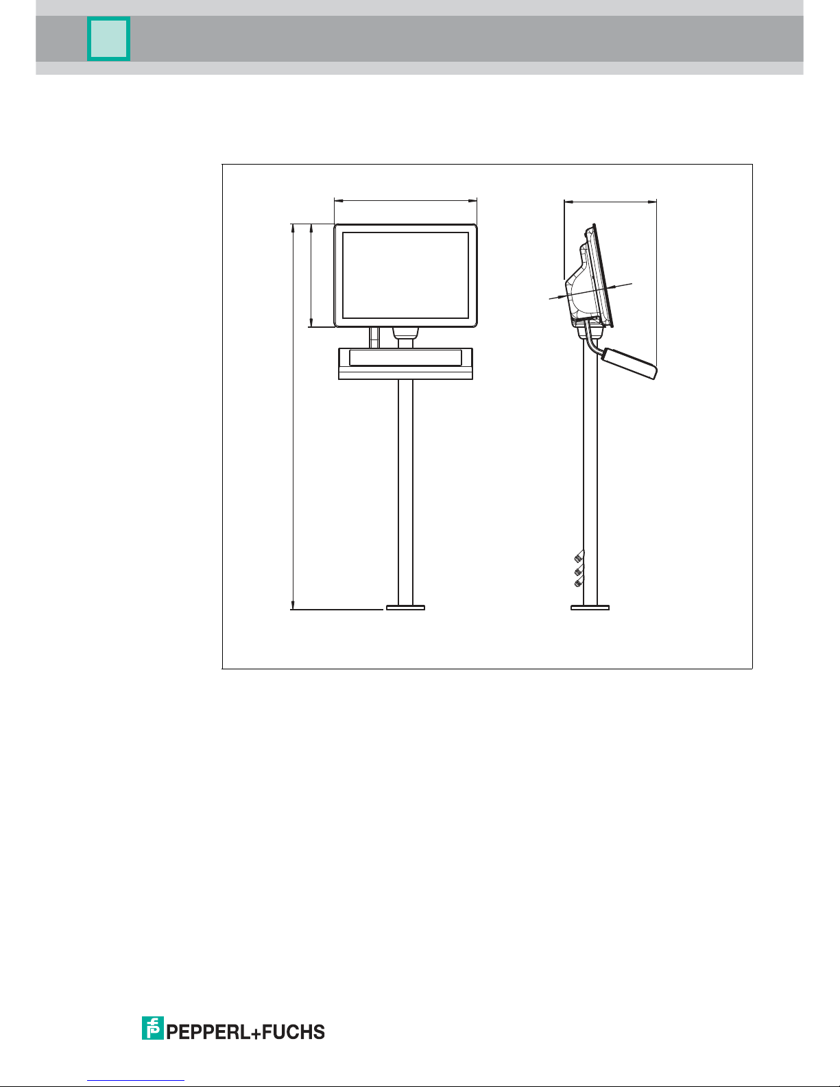
2.3 Dimensions
Dimensions
2.4 Scope of Delivery
■
1x Pre-assembled VisuNet RM-GXP Panel
■
(Option: Panel mounted into AG-XX00 housing)
■
2x Protective tubes
■
Screws for housing
624
451
1687
~ 400
173
Page 10

VisuNet GXP RM-GXP1100 and RM-GXP1200
Mechanical Installation
302041 2017 -05
11
3 Mechanical Installation
3.1 Unpacking
The VisuNet GXP is sent pre-assembled consisting of the core components Display Unit,
Power Supply Unit and Thin Client Unit. If the housing option is chosen, the pan el is sent premounted into the housing.
Warning!
Risk of injuries
Handling the devices with bare hands may cut fingers, hands, or wrists.
Make sure to wear gloves during the installation process at all times.
Caution!
Scratches and damages to the devices
The devices may become scratched or damaged if they a re placed onto or moved over hard
surfaces.
Use the foam brackets enclosed when taking the device out of the box or moving it around. Use
these brackets for placing the device and place it face down onto them, i.e. onto the display
front.
Warning!
Danger resulting from scratched display unit front screen
Scratches in a display unit front screen weaken the glass structure and may thus, in the event
of an explosion within the display unit, result in glass breakage. Explosion protection is no
longer ensured if a display unit with a scratched screen is used.
NEVER use a display unit with a scratched front screen in a hazardous area. If the surface is
damaged in any way, return the display unit to Pepperl+Fuchs at once and replace it with a new
one. To this end, remove the display unit. See chapter 3.2.7
Page 11

302041 2017 -05
12
VisuNet GXP RM-GXP1100 and RM-GXP1200
Mechanical Installation
Page 12

VisuNet GXP RM-GXP1100 and RM-GXP1200
Mechanical Installation
302041 2017 -05
13
3.2 System Installation
3.2.1 Preparing the Pedestal
For floor mounting, the preferred installation option is using PEDESTAL-XX00-*. This is shipped
with a pre-installed rotating coupling with four headless screws an d a grounding cable which is
fixed to the pedestal tube.
Preparing the Pedestal for Connection
1. Bend the grounding cable and place it within the pedestal tube.
2. Route the field installation cables (power cable, Ethernet cable) through the cable glands at
the pedestal bottom into the pedestal, through the pedestal tube, and out at the top.
3. Place the O-ring into the channel of the coupling.
The pedestal is now ready for connection.
Figure 3.1 Pedestal with PE cable
1 PE cable
1
Page 13

302041 2017 -05
14
VisuNet GXP RM-GXP1100 and RM-GXP1200
Mechanical Installation
3.2.2 Mounting the Housing
Mounting the AG-XX00 Housing onto the Pedestal
1. Align the rotatable coupling of the pedestal to match the hole pattern of the housing.
2. With the help of a crane or another person, place the housing onto the pedestal in such
a way that the screws align with the key slot hole and the housing rests on the pedestal.
Warning!
Risk of injuries
Lifting the device on your own may lead to injury.
Do not attempt to lift the device on your own. Use a crane or get another person to help you.
Warning!
Risk of injuries
While the device is resting on the pedestal and the nuts have not yet been fixed to the screws,
the device may tip over and fall off the pedestal, become damaged and cause injury.
Make sure to prevent the housing from tipping over by securing it manually (e.g. holding on to
it) until the nuts have been firmly attached to the screws and the housing is securely attached to
the pedestal.
Warning!
Damage to the PE cable
The PE cable may become damaged if it gets stuck between the pedestal and the housing.
Bend the PE cable in s uch a way that it does not get stuck between the pedestal and the
housing.
Page 14

VisuNet GXP RM-GXP1100 and RM-GXP1200
Mechanical Installation
302041 2017 -05
15
1. While manually securing the housing (e.g. by holding on to it), remove all screws from its
back.
2. While manually securing the housing (e.g. by holding on to it), slowly pull on both lower
corners of the display bezel until the display slides out of the housing completely.
3. While manually securing the housing (e.g. by holding on to it), slide the display panel
about 8 mm to the left to unlock the panel mechanism securing the display.
4. While manually securing the housing (e.g. by holding on to it), open the housing by
moving the display away from it.
Page 15

302041 2017 -05
16
VisuNet GXP RM-GXP1100 and RM-GXP1200
Mechanical Installation
While manually securing the housing (e.g. by holding on to it), tip the display panel towards
you until the display comes to rest in its fully openend position, hanging down at an angle from
its tightened strings.
Place the washers onto the screws and then use a tightening torque to attach the nuts to the
headless screws using a torque of 7.5 Nm.
1.
1.
2.
3.
Tip
Secure the screws with a medium strength bolt adhesive (e.g. Loctite® Threadlocker Blue
242®)
Page 16

VisuNet GXP RM-GXP1100 and RM-GXP1200
Mechanical Installation
302041 2017 -05
17
3.2.3 Closing the Housing
Closing the AG-XX00 Housing
1. To close the housing, put the display in an upright position by slowly moving it backwards
until the bolts touch the inner fram e of the housing and the panel is in its parking position.
2. To unlock the display panel, slide it about 8 mm to the right until the bolts match with the cutout holes of the inner frame.
3. Slowly and evenly push both lower corners of the display panel into the housing.
4. Press together display panel and housing at the top end of the system and place a screw
each in the holes at the upper left and upper right corners of the housing back.
Warning!
Risk of finger injury
Fingers can become squeezed in and stu ck when the display is moved backed into the
housing.
Wear protective gloves, hold the display panel by the fram e when moving it and mind your
fingers.
Warning!
Risk of cable damage
The cables may become squeezed in during the closing process.
Make sure to properly fix all the cables, place them in a protective tube and push that tube into
the pedestal before closing the housing.
1.
2.
3.
3.
Page 17

302041 2017 -05
18
VisuNet GXP RM-GXP1100 and RM-GXP1200
Mechanical Installation
5. Fasten the the two screws with a torque of 6 Nm .
6. Repeat the last step with all other screws following a diagonal pattern.
Page 18

VisuNet GXP RM-GXP1100 and RM-GXP1200
Mechanical Installation
302041 2017 -05
19
3.2.4 Mounting the Keyboard
The TASTEX EXTA 2 keyboard is the system keyboard available with a mounting option for the
VisuNet GXP housing AG-XX00.
Mounting the EXTA2-*-G-* Keyboard to Housing AG-XX00
1. Open and remove the four cover plate screws on the left side of the AG-XX00 housing bottom.
2. Route the keyboard cable with the protective tube through the hole of the AG-XX00.
1. Using the screws delivered with the EXTA2-*-G-* keyboard, attach the keyboard to the AGXX00 housing.
2. Fasten the the four screws w ith a torque of 6 Nm.
Tip
Secure the s crews with a medium strength bolt adhesive (e.g. Loctite® Threadlocker Blue
242®)
Page 19

302041 2017 -05
20
VisuNet GXP RM-GXP1100 and RM-GXP1200
Mechanical Installation
3.2.5 Mounting the Scanner Holder to the Housing
The SCANN ER-HOLDER-PSCAN-XX00-N0 (#548121) is a scanner holder for the PSCAN-*
scanner family that is compatible with the VisuNet GXP housing AG-XX00.
We recommend using the following tools for the installation:
■
Split socket pliers
■
Gloves
■
Hex key drivers (2.5 mm and 3 mm)
■
Flat wrench (10 m m)
Mounting SCANNER-HOLDER-PSCAN-XX00-N0 to Housing AG-XX00
1. Open the housing.
2. Remove the cover plate on the right side of the AG-XX00 housing by opening the w ing
screw which is located within the housing.
3. Affix the scanner holder with the first screw that is contained in the scope of delivery of the
scanner holder.
4. Use a hex key to put the first screw (with lock washer and sealing washer) through the
drilled hole at the left side of the AG-XX00 housing.
1.
1.
2.
3.
Page 20

VisuNet GXP RM-GXP1100 and RM-GXP1200
Mechanical Installation
302041 2017 -05
21
5. Press the scanner holder against the housing from the outside and fasten the screw using a
torqu e of 6 Nm.
6. Use the hex key to put the second screw (with lock washer and sealing washer) through the
drilled hole at the right side of the AG-XX00 housing and fasten the screw using a torque of
6 Nm .
The scanner holder is now fixed to the housing.
Page 21

302041 2017 -05
22
VisuNet GXP RM-GXP1100 and RM-GXP1200
Mechanical Installation
3.2.6 Installing the Scanner Cable
The DATL-PSCAN-D-XX00-N0 (#548133) is a cable for the installation of the PSCAN-D
barcode reader to the VIsu Net GXP RM/PC. The scanner cable is compatible with the VIsuNet
GXP housing AG-XX00 and allows to install the scanner interface plug into the housing.
Installing Scanner Cable DATL-PSCAN-D-XX00-N0
1. Open the housing.
2. To remove the plug at the bottom right side of the housing, hold its screw steady from below
using a screwdriver, while unwinding the screw from above usin g a wrench.
3. Put the cable through the hole with its open wire ending facing foward.
4. Add the M16 counter nut over the end of the cable.
5. Pull the socket into the housing and tighten it with the M16 counter nut. Tighten the screw
with a torque of 5 Nm.
6. Protect the cable from mechanical da mage by fixing it with a cable tie.
7. Route the cable into the computing unit by using the cable gland of the computing unit (TCU
or PCU). Install the cable ends as per the table below.
Wire Colors and Signals
Connect the plug of the PSCAN-D* barcode reader to the socket and tighten it firmly.
Wire Color Signal
Yellow US
White TxD
Green RxD
Brown a nd Gray GND
Note!
For more information regarding electrical installation, please refer to the computing unit (TCU or
PCU) manual or the PSCAN barcode reader ma nual.
Note!
The plug is secured with a nose. Ensure to match the nose with the socket during installation.
Page 22

VisuNet GXP RM-GXP1100 and RM-GXP1200
Mechanical Installation
302041 2017 -05
23
3.2.7 Dismounting the Display Unit
Dismounting the Display Unit
1. Open the housing (1). After de-energizing (s ee above), open the compartment room of the
computing unit. Then, remove all 10 screws from the back of the computing unit and take the
computing unit off from the display unit (2).
2. To ease the replacement of the display unit, temporarily affix the computing unit, e.g. by
using cable ties. To this end, put a cable tie through either m ounting hole at its top left and
top right, and hang the computing unit from the top of the enclosure frame.
Note!
For repair purposes, the display unit can be dismounted from the computing unit (TCU or PCU)
and be replaced individually.
Warning!
Danger of Explosion
An ignition may be triggered if the computing unit is still energized when its compartment room
is opened.
Make sure the computing unit is switched off and wait 3 minutes after de-energizing before
opening the compartment room of the computing unit.
1 Cable Ties
1.
2.
1
Page 23

302041 2017 -05
24
VisuNet GXP RM-GXP1100 and RM-GXP1200
Mechanical Installation
3. Remove the grounding cable from the grounding bolt at the back of the display unit.
1
4. Now the display unit can be rem oved from the enclosure completely. During the rem oval
process, make sure to hold the display unit steady so it cannot fall down, preferably with the
help of another person, and to place it on an upholstered and even surface after removal. To
remove the display unit from the enclosure, take the two strings out of the carabiners and
remove the 4 screws w ith which the 2 angle brackets are attached to the display unit (1).
Then remove the display unit from the h ousing (2).
1. Ple ase use a torque of 4 Nm for tightening t he grou nding bolt during th e displ ay unit reassembly proces s where
these steps are performed in reverse order.
2.
1.
Page 24

VisuNet GXP RM-GXP1100 and RM-GXP1200
Mechanical Installation
302041 2017 -05
25
5. Remove the two brackets (1) as well as the 10 bolts at the top, sides, a nd bottom of the
display unit (2). Then, remove the carabiners (3) from their brackets, take out the six bracket
screws (4), and remove the carabiner brackets.
1.
2.
4.
3.
Note!
To mount the new display unit, perform all of the above steps in reverse, mounting the items
you dismounted.
Page 25

302041 2017 -05
26
VisuNet GXP RM-GXP1100 and RM-GXP1200
Mechanical Installation
3.3 Panel Mount Installation
If the Panel Mount Option is chosen, you will receive a pre-assembled package consisiting of a
display unit, a computing unit, and a power supply unit.
The following kit for panel mounting can be ordered separately:
■
2x L-shaped panel mount brackets (1 left, 1 right)
■
1 rectangular stiffener frame
■
14x M5x25 socket head cap screw (torque: 1.8 Nm)
■
10x M5 lock nut (torqu e: 4 Nm)
For ordering details, see chapter 5.1
Panel Mounting the RM-GXP
1. Mount the first L-shaped bracket to the back of the display unit. Make sure to use the bracket
with the four extra holes at the bottom.
Note!
Please note that the mounting brackets are not identical, but two different items.
1 L-shaped bracket with extra holes at the bottom
1
Page 26

VisuNet GXP RM-GXP1100 and RM-GXP1200
Mechanical Installation
302041 2017 -05
27
2. From the front, place the panel in the cabinet cutout hole (1) and move it to an upright
vertical position (2).
3. From inside the cabinet, add the stiffener frame, position it (1)-(3), and press it against the
back of the cabinet wall.
1 Cabinet wall (back)
2 Stiffener Frame
1.
2.
3.
2
1
1.
2.
1.
Page 27

302041 2017 -05
28
VisuNet GXP RM-GXP1100 and RM-GXP1200
Mechanical Installation
4. Prepare the other L-shaped bracket with the mounting screws.
5. Mount the prepared L-shaped bracket to the display unit housing (1), then affix both Lshaped brackets with all screws to the stiffener frame (2).
6. Finally, tighten all the screws in a criss-cross pattern using 1.8 Nm torque for the 14x M5x25
socket head cap screws and 4 Nm for the 10x M5 lock nuts.
1.
2.
Page 28

VisuNet GXP RM-GXP1100 and RM-GXP1200
Electrical Installation
302041 2017 -05
29
4 Electrical Installation
When installing the VisuNet GXP system, always ensure a proper grounding of all components
including housing and mounting parts (e.g. pedestal, wall-bracket) with an area of at least 4
mm2according to IEC 60079-14.
The VisuNet GXP is shipped with the following PE wiring connections, if the housing option is
selected:
■
PE wire from the display unit grounding bolt to the housing AG-XX00 grounding bolt.
■
PE wire from the power supply unit grounding bolt to the housing AG-XX00 grounding
bolt.
Warning!
Danger of Explosion
Disconnecting cables too quickly may trigger an ignition, as device-internal cable capacitances
need some time to discharge.
After de-energizing, wait 3 m inutes before opening the compartment room or disconneting the
device from the display unit.
Warning!
Danger of Explosion
Cable insulation m ay become damaged if cables and connection lines are not used in
adequate temperature ranges. Thus, short circuits within the cable may occur which in turn may
give rise to sparks and/or surface temperatures capable of triggering an ignition.
Only use cables and connection lines which are suitable to be used within a temperatu re rating
of 80 °C if the system components are used within an ambient operating temperature of Ta > 40
°C.
Note!
Please refer to the manuals of the individual com ponents for further information on electrical
installation and wiring.
Danger!
Explosion hazard from wrong or missing grounding
Wrong or missing grounding can cause sparks. This can ignite the surrounding potentially
explosive atmosphere.
■
Ground the device. Observe th e grounding requirements.
■
Ensure that external ground connections exist, are in good condition, and are not
damaged or corroded.
Warning!
Risk of electric shock or property damage from inadequate grounding
If you do not ground the device correctly, this could result in potential equalization currents.
These currents could hurt operating personnel or cause property damage.
Ground the device via the grounding bolt. Ensure that a correct potential equalization is
guaranteed at all times.
Page 29

302041 2017 -05
30
VisuNet GXP RM-GXP1100 and RM-GXP1200
Electrical Installation
4.1 Grounding the Housing to the Pedestal
Grounding the AG-XX00 Housing to PEDESTAL-XX00-*.
1. Connect the pre-installed PE wire of the pedestal to the grounding bolt of the AG-XX00 housing.
2. Ground the pedestal with the grounding stud on the bottom plate of PEDESTAL-XX00-*.
3. Fasten the screw with a torque of 7.5 Nm .
Figure 4.1 Grounding Concept
1 Housing
2 Ground bolt (hexagon socket)
3 Contact washer
4 Nut
5 Cable lug
6 Flat washer
7 Spring washer
8 Nut
1
2
3
4
5
6
7
8
Page 30

VisuNet GXP RM-GXP1100 and RM-GXP1200
Electrical Installation
302041 2017 -05
31
4.2 Grounding the Housing to the Wall-Bracket
Grounding the AG-XX00 Housing to WALL-BRACKET-XX00-*
1. Ground the wall bracket with the grounding bolt on the bottom of the WALL-BRACKETXX00-*.
2. Fasten the screw with a torque of 6 Nm.
Note!
The AG-XX00 housing is grounded indirectly via the wall bracket. It does not require an
additional PE wire between housing and wall bracket.
Page 31

302041 2017 -05
32
VisuNet GXP RM-GXP1100 and RM-GXP1200
Appendix
5 Appendix
5.1 Accessories
Mounting and Installation
Barcode Reader
Item Number Name Description
#548003 PEDESTAL-XX00-124-3-304-TRN-N0 Turnable pedestal, floor mount
Compatible with AG-XX00-* housing
#548071 WALL-BRACKET-XX00-3-304-N0 Adapter for wall mounting installation
Compatible with AG-XX00-* housing
#548004 KIT-PM-XX00-22F-304-N0 Kit for panel mounting
Compatible with 21.5'' display unit
(option 22F)
Item Number Name Description
#548121 SCANNER-HOLDER-PSCAN-XX00-N0 Scanner holder for PSCAN-
D/PSCAN-M barcode reader
Compatible with AG-XX00-* housing
#548133 DATL-PSCAN-D-XX00-N0 Connector cable for PSCAN-D
barcode reader
Compatible with AG-XX00-* housing
Note!
For more options and accessories, please contact your local Pepperl+Fuchs sales
representative.
Page 32

Subject to modifications
Copyright PEPPERL+FUCHS • Printed in Germany
www.pepperl-fuchs.com
Worldwide Headquarters
Pepperl+Fuchs GmbH
68307 Mannheim · Germany
Tel. +49 621 776-0
E-mail: info@de.pepperl-fuchs.com
For the Pepperl+Fuchs representative
closest to you check www.pepperl-fuchs.com/contact
PROCESS AUTOMATION –
PROTECTING YOUR PROCESS
302041 / DOCT-5482
05/2017
 Loading...