

Pepperl+Fuchs VisuNet GMP DM200 Series, VisuNet GMP DM219, VisuNet GMP DM222, VisuNet GMP DM221 Hardware Manual
Page 1
PROCESS AUTOMATION
MANUAL
VisuNet GMP DM200 Series
Hardware Manual
Page 2

With regard to the supply of products, the current issue of the following document is ap-
plicable: The General Terms of Delivery for Products and Services of the Electrical Indus-
try, published by the Central Association of the Electrical Industry (Zentralverband
Elektrotechnik und Elektroindustrie (ZVEI) e.V.) in its most recent version as well as the
supplementary clause: "Expanded reservation of proprietorship"
VisuNet GMP DM
Page 3

VisuNet GMP DM
3
1 Safety .......................................................................................... 5
1.1 Validity................................................................................................... 5
1.2 Symbols Used ...................................................................................... 5
1.3 System Operator and Personnel ........................................................ 5
1.4 Pertinent Laws, Standards, Directives, and further Documentation5
1.5 Intended use......................................................................................... 6
1.6 Installation and commissioning ......................................................... 6
2 Product Specifications............................................................... 7
2.1 Overview ............................................................................................... 7
2.2 Technical Data ...................................................................................... 8
2.3 Dimensions VisuNet GMP DM series ................................................. 9
2.4 Interfaces and connectionsVisuNet GMP DM ................................. 10
2.4.1 VGA interface................................................................................... 10
2.4.3
Supply Voltage 24 V......................................................................... 11
2.4.4 Supply Voltage 120/230 V (AC)........................................................ 11
2.5 Accessories........................................................................................ 12
2.5.1
Keyboards........................................................................................ 12
2.5.2
Pedestals ......................................................................................... 15
2.5.3
Wall arm versions............................................................................. 16
2.5.4
Wall bracket ..................................................................................... 16
2.5.5
Hole pattern of the mounting versions.............................................. 17
2.5.6 Power supply accessories................................................................ 18
2.4.2
DVI interface..................................................................................... 10
2.5.7 Barcode reader................................................................................. 18
2.5.8 Dimensions with barcode handheld.................................................. 19
2.5.9 Holder for handheld barcode reader................................................. 20
3 Installation an
d Commissioning ............................................. 21
3.1
Preparation ......................................................................................... 21
3.2 Mounting in the field.......................................................................... 21
3.2.1 Grounding at pedestal an
d wall arm................................................. 21
3.3 Commissioning VisuNet GMP .......................................................... 22
2.4.5
Supply voltage 12 V (PA version) ..................................................... 11
Page 4

4
VisuNet GMP DM
4.1
On Screen Display..............................................................................24
4.1.1
Audio menu ...................................................................................... 26
4.1.2
Bright-Contrast menu ....................................................................... 27
4.1.3
Menu Color ...................................................................................... 28
4.1.4
Image menu ..................................................................................... 29
4.1.5
Tools menu ....................................................................................... 30
4.1.6
Input menu ....................................................................................... 31
4.1.7
Exit menu ......................................................................................... 32
5 Appendix ................................................................................... 33
5.1 Chemical resistance of keyboard foil ...............................................33
5.2 Chemical resistances of the touch screen ......................................33
4 Operation................................................................................... 24
Page 5

VisuNet GMP DM
Sicherheit
219365 2017-02
5
1
1.1
1.2
Safety
Validity
The chapter “Safety” is valid as inst
ruction manual.
Specific processes and instructions in this instruction manual require special provisions to
guarantee the safety of the operating personnel.
Symbols Used
This document contains symbols for the identification of warning messages and of informative
messages.
Warning Messages
You will find warning messages, whenever dangers may arise from your actions. It is mandatory
that you observe these warning messages for your personal safety and in order to avoid
property damage.
Depending on the risk level, the warning messages are displayed in descending order as
follows:
Informative Symbols
Action
This symbol indicates a paragraph with instructions. You are prompted to perform an action or
a sequence of actions.
1.3 System Operator and Personnel
Responsibility for planning, assembly, commissioning, operation, maintenance, and
dismounting lies with the plant operator.
The personnel must be appropriately trained and qualified in order to carry out mounting,
installation, commissioning, operation, maintenance, and dismounting of the device. The
trained and qualified personnel must have read and understood the instruction manual.
1.4 Pertinent Laws, Standards, Directives, and further Documentation
Observe laws, standards, and directives applicable to the intended use and the operating
location. Observe Directive 1999/92/EC in relation to hazardous areas.
Danger!
This symbol indicates an imminent danger.
Non-observance will result in personal injury or death.
Warning!
This symbol indicates a possible fault or danger.
Non-observance may cause personal injury or serious property damage.
Caution!
This symbol indicates a possible fault.
Non-observance could interrupt the device and any connected systems and plants, or result in
their complete failure.
Note!
This symbol brings important information to your attention.
Page 6

219365 2017-02
6
VisuNet GMP DM
Sicherheit
1.5
1.6
The corresponding datasheets, manuals, declarations of conformity, EU-type examination
certificates, certificates, and control drawings if applicable (see datasheet) are an integral part
of this document. You can find this information under www.pepperl-fuchs.com.
Due to constant revisions, documentation is subject to permanent change. Please refer only to
the most up-to-date version, which can be found under www.pepperl-fuchs.com.
Intended use
The device is only approved for appropriate and intended use. Ignoring these instructions will
void any warranty and absolve the manufacturer from any liability.
The devices must not be repaired, changed or manipulated. If there is
a defect, the product
must always be replaced with an original device.
Installation and commissioning
The device must only be operated in the specified ambient temperature range and at the
specified relative humidity without condensation. The device is rated up to 2000 m and is
intended to be used in a Pollution Degree 2 environment.
Overcurrent protection is achieved external to the equipment: 15 A overcurrent protection must
be provided by the building installation.
A readily accessible disconnect device must be incorporated external to the equipment.
Use shielded cable
To connect interfaces only use shielded cable.
Screwing/locking connectors
To advance the cable shield screw/lock the connectors.
The device must be disconnected from the power supply prior to installation and maintenance.
The power supply may be activated only after all the circuits required for operation have been
fully assembled and connected.
Leading of data cables and power circuit lines
Lead data cable and power circuit line in separate cable channels.
Check cables and connectors
Before commissioning the system check all cables and connectors.
Page 7
VisuNet GMP DM
Product Specifications
219365 2017-02
7
2
2.1
Product Specifications
Overview
GMP (“Good Manufacturing Practice”) is a set of guidelines for assuring the quality of
production processes in controlled industries and closely follow th
e guidelines issued by the
European Commission or the FDA in the US. GMP applications are typically used in the
pharmaceutical and food industries. However, products that conform with GMP guidelines are
also required for the manufacture of cosmetics and fragrances or flavors.
The materials selected, design of the surfaces, and architecture of the overall system should
prevent the accumulation of fluids and dirt. Cleaning, maintenance, inspection and servicing
must be as safe and easy as the processes employed for the disinfection of mechanical
components.
The VisuNet GMP product portfolio extends from simple direct monitors and remote monitor
systems with Ethernet connection to a host, to complete PCs available with single or dual
monitor systems and various mounting options. Models feature a 19-inch, 21-inch, or 22-inch
display with an optional touch screen. The stainless steel housings have an IP65 degree of
protection. Remote monitors and PCs are equipped with Ethernet, USB, PS/2, and RS232
interfaces.
The VisuNet GMP product family guarantees a perfect fit for every system infrastructure.
Four models are available depending on the functions required, the display and input unit, and
the distance over which the data is transferred. This manual describes the VisuNet GMP direct
monitor (DM):
VisuNet GMP DM are direct monitors that are directly connected to the VGA or DVI interface
of the host. Industrial keyboards with integral mouse connected directly to the host are
available as accessories.
Page 8
219365 2017-02
8
VisuNet GMP DM
Product Specifications
Overview of features
■ The brilliant display provides high meter-reading comfort
■ Easy, user-friendly operation due to optionally available touch screen
■ Image position, pixel frequency, and phase will be detected and
synchronized automatically
■ Rugged
stainless steel housing (304/1.4301 - others on demand)
■ Degree of protection IP65
■ High-end finish of all surfaces
2.2 Technical Data
max. 5 m
DM
HOST
VisuNet GMP DM219 VisuNet GMP DM221 VisuNet GMP DM222
General specifications
Ty p e Direct monitor
Supply
Power supply
20 ... 30 V DC; 90 ... 240 V AC, 50 ... 60 Hz
Power consumption 40 W
Indicators/operating means
Display
Ty p e TFT, LCD, High Color (24 bit)
Screen diagonal 19 ''
21.5 "
22 "
Resolution 1280 x 1024 Pixel 1920 x 1080 Pixel 1680 x 1050 Pixel
Representable colors 16,7 Mio.
Brightness
300 cd/m
2
Page 9
VisuNet GMP DM
Product Specifications
219365 2017-02
9
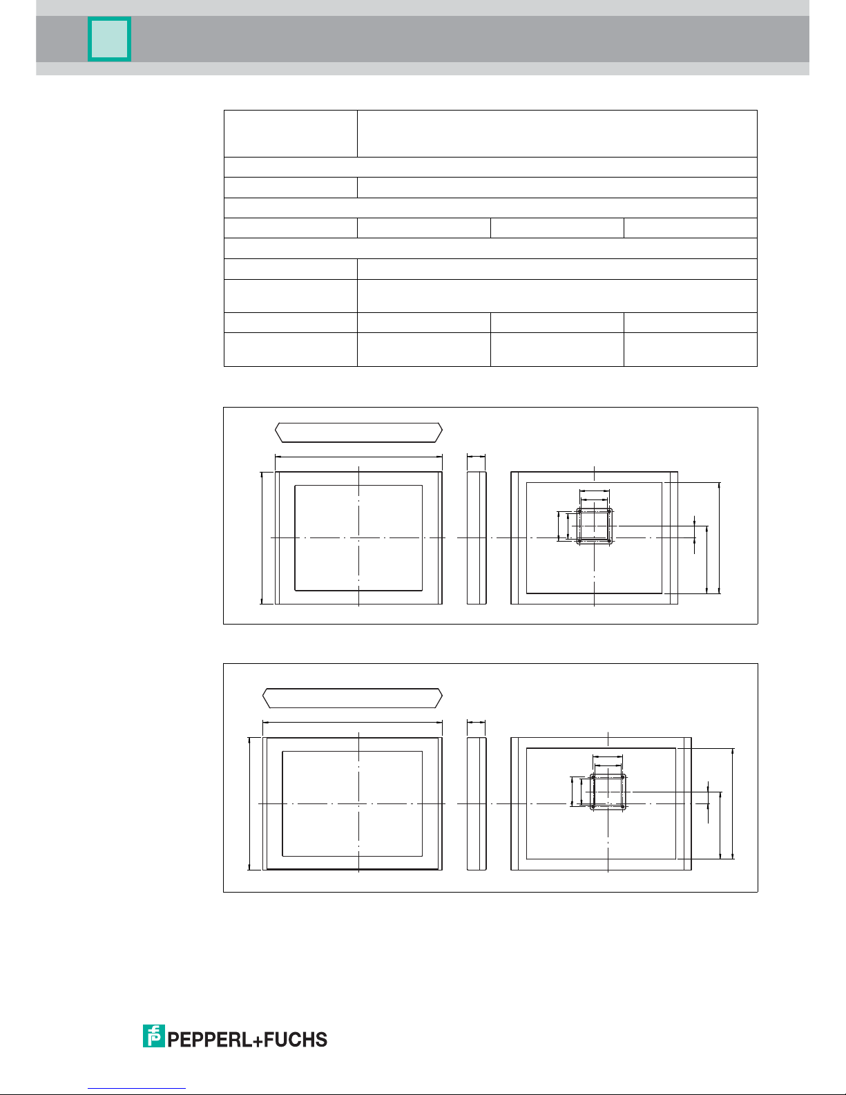
2.3 Dimensions VisuNet GMP DM series
Figure 2.1 Dimensions DM219
Figure 2.2 Dimensions DM221/DM222
Input devices Analog resistive touchscreen (optional) ,
Input device combined with keyboard and optional trackball/touch
screen/joystick
Interface
Interface type
VGA or DVI
Ambient conditions
Ambient temperature 0 ... 50 °C 0 ... 50 °C
0 ... 45 °C
Mechanical specifications
Protection degree IP65
Installation panel mounting
several mounting devices (rotatable/fix) available
Mass 18 kg 20 kg 20 kg
Dimensions 568 mm x 450 mm x
65 mm
625 mm x 450 mm x
73 mm
625 mm x 450 mm x
73 mm
9
10
9
10
228.5
378
39.5
568
450
73
9
10
9
10
228.5
378
39.5
625
450
73
Page 10
10
VisuNet GMP DM
Product Specifications
2.4
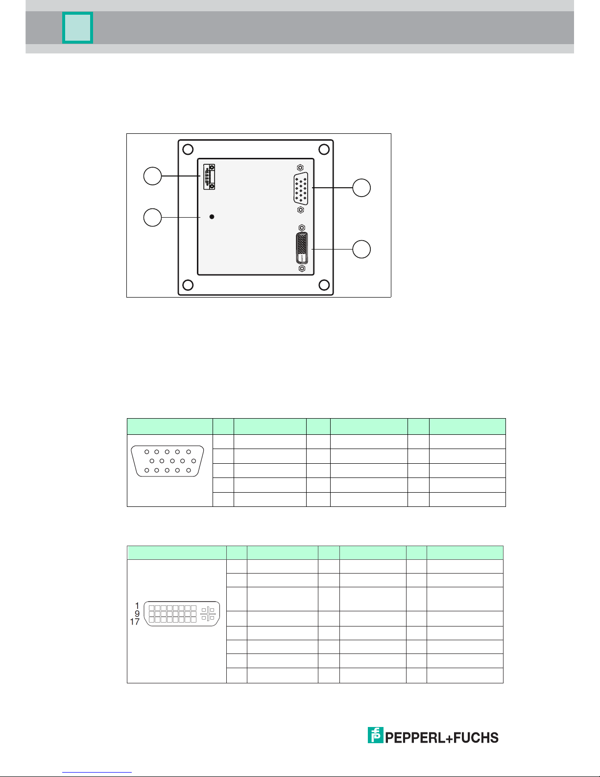
Interfaces and connections VisuNet GMP DM
The interfaces and connections of the VisuNet GMP are located within the VESA adapter at the
back of the housing.
The following interfaces are available:
Figure 2.3 VESA adapter at the back of the VisuNet GMP housing
2.4.1
VGA interface
15-pin HD-D-Sub socket "VGA" required for monitor/host connection.
Picture Pin Signal Pin Signal Pin Signal
1 RED 6 RED_GND 11 not in use
2 GREEN 7 GREEN_GND 12 IIC-DATA
3 BLUE 8 BLUE_GND 13 HSYNC
4 not in use 9 + 5 V 14 VSYNC
5 GND 10 GND 15 IIC-CLOCK
1
6
5
15 11
A
B
C
D
Phoenix DFK-MSTB 2,5/4-GF-5,08
Ground connection (M4)
VG interA face
DVI interface
C
D
A
B
2.4.2
DVI interface
Picture Pin DVI-D Pin DVI-D Pin DVI-D
1 TMDS data 2 - 9 TMDS data 1 - 17 TMDS data 0 -
2 TMDS data 2 + 10 TMDS data 1 + 18 TMDS data 0 +
3 TMDS data 2/4
shield
11 TMDS data 1/3
shield
19 TMDS data 0/5
shield
4 TMDS data 4 - 12 TMDS data 3 - 20 TMDS data 5 -
5 TMDS data 4 + 13 TMDS data 3 + 21 TMDS data 5 +
6 DDC clock (SCL) 14 +5 VDC 22 TMDS clock shield
7 DDC data (SDA) 15 Ground 23 TMDS clock +
8 Not used 16 Hot plug detect 24 TMDS clock -
219365 2017-02
Page 11
VisuNet GMP DM
Product Specifications
219365 2017-02
11
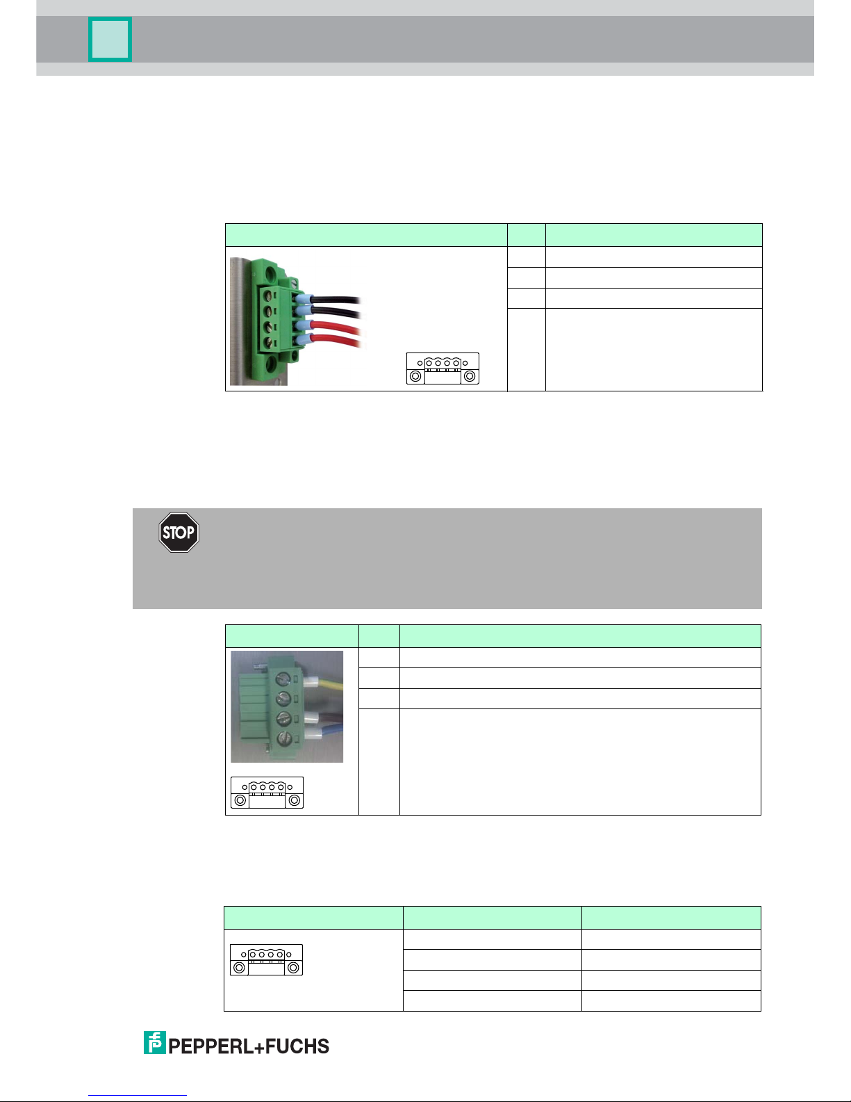
2.4.3
Supply Voltage 24 V
4-pin socket required for supply voltage connection (Phoenix Contact DFK-MSTB 2,5/ 4-GF5,08).
The VisuNet GMP KM has inverse-polarity protection.
Matching plug: Phoenix Contact MSTBT 2,5/ 4-STF-5,08
2.4.5 Supply voltage 12 V (PA version)
Required for supply voltage connection via terminal block.
Picture Pin Signal
1 GND
2 GND
3 + 24 V DC
4 + 24 V DC
1
2
3
4
41
Picture Pin Signal
1 GND
2 GND
3 + 12 V DC
4 + 12 V DC
41
2.4.4 Supply Voltage 120/230 V (AC)
4-pin socket required for supply voltage connection (Phoenix Contact DFK-MSTB 2,5/ 4-GF5,08).
Matching plug: Phoenix Contact MSTBT 2,5/ 4-STF-5,08
Danger!
Electric shock
Substantial material damage, personal injury, or even death.
Connect the 4-pin socket as shown in the following table. Only connect the voltage
supply when the device is completely installed.
Picture Pin Signal 120/230 V AC
1 PE
2 n. c.
3 L
4 N
1
2
3
4
41
Page 12

VisuNet GMP DM
Product Specifications
12
2.5
2.5.1
Accessories
The following accessories are available.
Keyboards
There are several keyboard models available. All keyboards
have an antibacterial coating.
For this reason, the keyboards are perfectly suitable for environments with high hygienic
standards.
Keyboard TA3-K4
Keyboard with touchpad for controlling the mouse pointer.
2 separate buttons below the touchpad assume the function of left and right mouse button.
Figure 2.4 Keyboard with touchpad
TA 3- K 4
General specifications
Ty p e Keyboard with touchpad
Supply
Rated voltage via data line
Indicators/operating means
Keyboard 105 short stroke keys
Keyboard layout: US international, German, French, (further
keyboard layouts on demand)
Touchpad
Active Principle capacitive
Resolution 40 Pts./mm
Dimensions 66 x 50 mm
Driver Microsoft Mouse ® , USB
Interface
Interface type USB
Conformity
Protection degree IP65
Ambient conditions
Ambient temperature -20 ... 50 °C (-4 ... 122 °F)
219365 2017-02
Page 13

13
VisuNet GMP DM
Product Specifications
Keyboard TA3-K6
Keyboard with joystick for controlling the mouse pointer.
2 separate buttons below the joystick assume the function of left and right mouse button.
Figure 2.5
Keyboard with joystick
Sto rage tempe rat ure -20 ... 70 °C (-4 ... 158 °F)
Relative humidity max. 85 % , non-condensing
Mechanical specifications
Material anodized aluminium , Polyester foil
Mass 1.2 kg
Dimensions 482.6 mm x 177.8 mm x 45 mm
Cable length 1.8 m , wire end ferrule
TA 3- K 6
General specifications
Ty p e Keyboard with joystick
Supply
Rated voltage via data line
Indicators/operating means
Keyboard 105 short stroke keys
Keyboard layout: US international, German,
French, (further keyboard layouts on demand)
Joystick
Driver Microsoft Mouse ® , USB
Interface
Interface type USB
Conformity
Protection degree IP65
TA 3- K 4
219365 2017-02
Page 14

VisuNet GMP DM
Product Specifications
14
Keyboard TA3-K8
Keyboard with optical trackball for controlling the mouse pointer.
2 separate buttons below the trackball assume the function of left and right mouse button.
Figure 2.6
Keyboard with optical trackball
Ambient conditions
Ambient temperature -20 ... 50 °C (-4 ... 122 °F)
Sto rage tempe rat ure -20 ... 70 °C (-4 ... 158 °F)
Relative humidity max. 85 % , non-condensing
Mechanical specifications
Material anodized aluminium , Polyester foil
Mass 1.2 kg
Dimensions 482.6 mm x 177.8 mm x 45 mm
Cable length 1.8 m , wire end ferrule
TA 3- K 8
General specifications
Ty p e Optical trackball
Supply
Rated voltage via data line
Indicators/operating means
Keyboard 105 short stroke keys
Keyboard layout: US international, German,
French, (further keyboard layouts on demand)
Trackball
Diameter 50 mm
Material Phenolic resin, polyester, epoxide resin (grey)
Driver Microsoft Mouse ® , USB
TA 3- K 6
219365 2017-02
Page 15

15
VisuNet GMP DM
Product Specifications
2.5.2
Pedestals
Figure 2.7
Pedestal models for VisuNet GMP
Interface
Interface type USB
Conformity
Protection degree IP65
Ambient conditions
Ambient temperature 0 ... 50 °C (32 ... 122 °F)
Sto rage tempe rat ure -10 ... 70 °C (14 ... 158 °F)
Relative humidity max. 85 % , non-condensing
Mechanical specifications
Material anodized aluminium , Polyester foil
Mass 1.2 kg
Dimensions 482.6 mm x 177.8 mm x 45 mm
Cable length 1.8 m , wire end ferrule
TA 3- K 8
AA ABB B
A
1500
500
1000
155
300
1270
1000
560
750
420
225
350
540
2 3 4 5 6 71
Model number Description
1 PEDESTAL1-150-1V-KP-G-T-304 Pedestal, turnable approx. 350°, inclination of monitor 10°, with pipe
for keyboard
2 PEDESTAL1-150-1V-KP-G-F-304 Pedestal, fix mounted, inclination of monitor 10°, with pipe for
keyboard
3 PEDESTAL1-150-1V-NP-G-T-304 Pedestal, turnable approx. 350°, inclination of monitor 10°
4 PEDESTAL1-150-1V-NP-G-F-304 Pedestal, fix mounted, inclination of monitor 10°
5 PEDESTAL1-130-3V-NP-G-T-304 Pedestal, turnable approx. 350°, inclination of monitor 30°
6 PEDESTAL1-130-3V-NP-G-F-304 Pedestal, fix mounted, inclination of monitor 30°
7 PEDESTAL1-56-3V-NP-G-T-304 Pedestal turnable approx. 350°, inclination of monitor 30°
219365 2017-02
Page 16

219365 2017-02
16
VisuNet GMP DM
Product Specifications
2.5.3 Wall arm versions
Figure 2.8 Wall arms for VisuNet GMP
2.5.4 Wall bracket
Figure 2.9 Wall bracket for VisuNet GMP
Model number Description
1 WALL-ARM1-55-
1V-NT-G-*-304
Wall arm, inclination of monitor 10°, without pipe for keyboard
2 models available:
■ WALL-ARM1-55-1V-NT-G-F-304: fix
■ WALL-ARM1-55-1V-NT-G-T-304: approx. 350° turnable
2 WALL-ARM1-55-
0V-KT-G-*-304
Wall arm, without inclination of monitor, with pipe for keyboard
2 models available:
■ WALL-ARM1-55-0V-KT-G-F-304: fix
■ WALL-ARM1-55-0V-KT-G-T-304: approx. 350° turnable
21
B B
500
775
575
100
250
815
520
865
990
285
Model number Description
1 WALL-
BRACKET1-0-0VG-304
Wall bracket
1
C
Page 17

VisuNet GMP DM
Product Specifications
219365 2017-02
17
2.5.5 Hole pattern of the mounting versions
Figure 2.10 Bottom attachment, turnable, fastening at front
Figure 2.11 Bottom attachment, fix mounted
Figure 2.12 Wall bracket
129
9
40
A
42-50
90
9
63-64
B
Ø
17
280
9
15
105
C
Page 18

219365 2017-02
18
VisuNet GMP DM
Product Specifications
2.5.6 Power supply accessories
Power supply
Model number Description
BN-24/5000-HS-10 Power supply
DATL-A2-2.5-0 Power cable 2x 2.5mm², wire end ferrule, max. length 80 m
DATL-A2-4.0N/2.5F-1 Power cable 2x 4.0mm² +2.5m 2.5mm², wire end ferrule, length:
110 m
2.5.7 Barcode Reader
The VisuNet GMP has an option for connection of a handheld barcode reader. The
following products can be used at present:
Barcode handheld Powerscan PSCAN-D-1D-N0-R3-10-N
The PSCAN-D-1* consists of a barcode handheld with connecting cable. The
connecting cable is a ʾ m long cable, and an 8-pin M12 connector is mounted.
Order designation PSCAN-D-1*
Device Order designation Description
PSCAN-D-1* PSCAN-D-1D-N0-R3-10-N Barcode handheld
NON-Ex
Sparepart cable SPAREPARTS-PSCAN-D-GP-CABLE-20 Sparepart cable for
PSCAN-D-1D-N0-R3-10-N
Page 19

19
VisuNet GMP DM
Product Specifications
2.5.8 Dimensions with Barcode handheld
Dimensions VisuNet GMP DM 219 with Barcode handheld
Dimensions VisuNet GMP DM 221 and DM 222 with Barcode handheld
682
29,5
~187
~97
131
74
152
85
152
13
450
73
740
29,5
~187
~97
131
74
152
85
152
13
450
74
219365 2017-02
Page 20

VisuNet GMP DM
Product Specifications
20
2.5.9
Holder for handheld barcode reader
Dimensions
85
30
71,5
90
120
152
14
67,6
219365 2017-02
Page 21

VisuNet GMP DM
Installation and Commissioning
219365 2017-02
21
3 Installation and Commissioning
3.1 Preparation
Unpacking the unit
1. Check that all package contents are present and undamaged.
If anything is damaged, inform the shipper and contact the supplier.
2. Check that all items are present and correct based on your order and the shipping
documents.
3.2
If you have any questions, please contact Pepperl+Fuchs.
3. Keep the original packing material in case you need to store or ship the unit at a later time.
Mounting in the field
The device is licensed for operation in confined spaces.
The cooling of the device does not require active components like CPU fan or water cooling
systems. For that
reason there are no ventilation slots in the housing.
To avoid overheating during operation, follow the guidelines below for field installation:
■ Do not expose the device to direct solar radiation or other heat sources.
■ Since the heat will dissipate via the housing, provide sufficient air circulation.
■ Keep the ambient temperature below the specified maximal value.
3.2.1 Grounding at pedestal and wall arm
Figure 3.1 Ground connection at pedestal/wall arm
Note!
The device is not delivered in sterile condition.
Note!
Pepperl+Fuchs recommends using a cable with a core-cross section of 4 mm2 for
grounding.
Page 22

219365 2017-02
22
VisuNet GMP DM
Installation and Commissioning
Grounding VisuNet GMP at pedestal and wall arm
1. Insert the grounding cable into a cable lug (4).
2. Unscrew the M4 screw on ground connection.
3. Insert the cable of the cable lug between the 2 washers (1).
4. Tighten the screw.
Figure 3.2 Grounding at Pedestal/Wall Arm
3.3
Commissioning VisuNet GMP
Use a low-restistance connection between device and control cabinet. Use
cables with a minimum cross core-section of 2,5 mm2 for power supply.
Turning on the VisuNet GMP
1. Connect the 4-pin plug with the 4-pin power supply socket at the back of the housing.
2. Fix and tighten the screws of the plug.
3. Switch on the power supply at source.
After establishing the power supply, the VisuNet GMP starts automatically. The
green LED on the right-hand side of the housing indicates a correct power supply.
Note!
Depending on the grounding cable, you need the adequate cable lug (not included in
delivery).
1 washer
2 lock washer
3 M4 screw
4 cable lug
1
2
3
4
Page 23

VisuNet GMP DM
Installation and Commissioning
219365 2017-02
23
Turning off the VisuNet GMP
1. Disconnect the
device from the power supply.
2. After that, unscrew the power plug at the VisuNet GMP.
Note!
Use the VisuNet GMP only with safety-low voltage (protective extra-low-voltage). The power
supply needs to be in line with applicable standards.
Page 24

219365 2017-02
24
VisuNet GMP DM
Operation
4
4.1
Operation
On-Screen Dis
play
VisuNet GMP features a graphical user interface for setting up the display via the on-screen
display (OSD menu). A control panel with four buttons for operating the system is located on
the right-hand side of the housing.
The following table describes the buttons and their functions.
Selecting the OSD menu
To s
elect the OSD menu, press the button.
The OSD menu is divided in the following menu items:
■ Color
■ Image Setting
■ Position
■ OSD Menu
■ Language
■ Misc.
■ Exit
Picture Button Function Description
Menu Menu selection
1. First click: activates menu
2. Second click: quits sub
menu/menu
Select menu
access/selection
1. Select menu entries
2. Confirm active menu entries
– downwards/left
1. Navigate in menus: downwards/left
2. Decrease a value
3. shortcut for audio volume
+ upwards/right
1. Navigate in menus: upwards/right
2. Increase a value
LED Stat us red light: no signal
green light: operating status
"on"
Menu
Select
–
+
Menu
Page 25

VisuNet GMP DM
Operation
219365 2017-02
25
Navigating in the OSD menu
1. If applicable select the OSD menu.
2. Navigate to the designated tab with the button (scroll to the right) and button
(scroll to the left) respectively.
The active tab will be marked.
3. To select a tab, press the button.
The sub menu will be opened.
4. Navigate to the designated sub menu entry with the button and the button
respectively
5. To select a sub menu, press the button.
Depending on the menu you will get to another sub menu or to a dialog box.
Adjusting values
1. To
adjust values (e.g. brightness or contrast) in a sub menu, press the
button and the
button respectively.
2. After adjusting the value, quit the active dialog box by pressing the button.
The adjusted value will be adopted and you will return to the designated sub menu.
Quitting OSD menu/sub menus
To quit a sub menu, select the menu item Back or press the button.
The sub menu will be quit.
+
–
Select
+
–
Select
+
–
Menu
Menu
Note!
Image Sticking
Displaying a fixed pattern may cause burn-in-effects (image sticking due to the LCD
characteristics).
To avoid image sticking, change
pattern frequently or activate screen saver.
Please note that display damage caused by burn-in effects is not included in the
warranty.
Page 26

219365 2017-02
26
VisuNet GMP DM
Operation
4.1.1 Audio menu
Menu item Name Description
Volu me Change the volume
Mute Mute the audio
Exit Quit the sub menu and return
to the menu one lever higher.
Note!
The VisuNet GMP has no audio speaker.
Page 27

VisuNet GMP DM
Operation
219365 2017-02
27
4.1.2 Bright-Contrast menu
Menu Item Name Description
Brightness Decrease/increase brightness
Contrast Decrease/increase contrast
Exit Quit the sub menu and return
to the menu one lever higher.
Page 28

219365 2017-02
28
VisuNet GMP DM
Operation
4.1.3 Menu Color
Sub menu Description
Contrast Adjust the contrast of the image
Brightness Adjust the brightness of the image
Color Adjust
Adjust the value of red, green, and blue
Color Temp Adjust the color temperature
Auto Color Run the auto config of the color
Back Back to main menu
Page 29

VisuNet GMP DM
Operation
219365 2017-02
29
4.1.4 Image menu
Sub menu Description
Clock Adjust the clock of the image
Phase Adjust the phase of the image
Ga m m a Adjust the gamma level of the image
Sharpness Adjust the sharpness of the image
Auto Adjust... Run the auto config of the image
Back Back to main menu
Page 30

219365 2017-02
30
VisuNet GMP DM
Operation
4.1.5 Tools menu
Menu item Name Description
OSD Select more sub menus: time,
horizontal,vertical, OSD menu
direction, exit
Reset Reset to factory settings
Sharpness Change sharpness
Language Change language of OSD
menu
Exit Quit the sub menu and return
to the menu one lever higher.
A
AA
Page 31

VisuNet GMP DM
Operation
219365 2017-02
31
4.1.6 Input menu
Menu item Name Description
VGA Activate VGA interface
DVI Activate DVI interface
Exit Quit the sub menu and return
to the menu one lever higher
1
2
Page 32

219365 2017-02
32
VisuNet GMP DM
Operation
4.1.7 Exit menu
Page 33

VisuNet GMP DM
Appendix
219365 2017-02
33
5
5.1
Appendix
Chemical resistance of keyboard foil
The keyboard foil is manufactured from a biaxially aligned polyester-based material and
therefore has a greater restistance to solvents. The foil is stronger and more durable than other
standard foils used on keyboards and front pa
nels, such as polycarbonate and PVC.
The keyboard foil is resistant against the following substances: (Test method: DIN42115):
■ Alcohols
■ Dilute acids
■ Dilute alkalis
■ Esters
■ Hydrocarbons
■ Household cleaning
5.2 Chemical resistances of the touch screen
The foil is manufactured from a biaxially aligned polyester-based material and therefore has a
greater restistance to solvents. It is physically resistant to pencil lead with a maximum hardness
of 3HB.
The foil is resistant against the following substances (concenration 100 % - unless otherwise
specified):
Aldehyde:
Acetataldehyde Formaldehyde 37 - 42 %
Alcohols:
Ethanol Hexahydrophenol
Tr i a c e t i n Dowandol DRM/PM
Glycol Glycerin
Isopropanol Methanol
Diacetone alcohol
Hydrocarbons:
Aliphatic hydrocarbons generally gasoline
Kerosene To l u o l
Xylene Benzene
Chlorinated hydrocarbons:
Chlorofluorocarbons Perchloroethylene
III-Trichloroethylene Diethyl ether
Methyl ethyl ketone Trichloroethylene
Acids:
Formic acid <10 % acetic acid <10 %
Phosphoric acid <10 % Hydrochloric acid <10 %
Nitric acid <10 % Trichloroacetic acid <10 %
sulfuric acid <10 %
Other organic solvents:
Ether Acetone
Page 34

219365 2017-02
34
VisuNet GMP DM
Appendix
Dimethylformamide Dioxane
Ethyldioctyl Dibutyl phthalate
Phthalate Butyl cellosolve
Iron chlorid (FeCl2) Iron chlorid (FeCl3)
Lyes:
Ammonia <10 % Sodium hydroxide <10 %
Alkali carbonate
Ester:
Ethylacetate N-butyl acetate
Amyl acetate
Technical oils and greases:
Drilling emulsion Diesel oil
Varnish Heating oil
Liquid paraffin Castor oil
Silicone oil Turpentine oil substitute
Brake fluid Decon
Saline solutions:
Alkali carbonate Bichromate
Potassium hydroxide <30 % Acetonitrile
sodium bisulfate potassium ferrocyanide
Sodium hypochlorite <20 %
Various other substances:
Molecular chlorine Cresol phenol soaps in hydrogen soution
Oxygen Tricresyl phosphate
Water <100 °C Hydrogen peroxid <25%
Saline water Solvent (white spirit)
Grape juice Milk
Coffee
Detergent, rising agent, cleaning agent:
Potash soap Detergent solutions (surfactants)
Fabric softener Sodium carbonate
Household chemicals (24 hours of exposure at 50 °C)
To p Jo b Jet Dry
Gumption Fantastic
Formula 409 Ariel
Persil Wisk
Lenor Downey
Ajax Vim
Domestos Vortex
Windex0
Aldehyde:
Page 35

VisuNet GMP DM
Appendix
219365 2017-02
35
Resistance to surface desinfectant can be determined on request.
Slight discoloration
Intense examinations established that the following products caused slight discoloration:
■ Mustard
■ Tomato juice
■ To m at o k e tch up
■ Lemon juice
No resistance
Not resistant to:
■ concentrated mineral acids
■ concentrated alkaline solutions
■ High-pressure steam over 100 °C
Note!
Various other substances may cause the surface structure to alter. Testing and subsequent
assessment still require clarification.
Page 36

Subject to modifications
Copyright PEPPERL+FUCHS •
Printed in Germany
www.pepperl-fuchs.com
Worldwide Headquarters
Pepperl+Fuchs GmbH
68307 Mannheim · Germany
Tel. +49 621 776-0
E-mail: info@de.pepperl-fuchs.com
For the
Pepperl+Fuchs representative
closest to you check www.pepperl-fuchs.com/contact
PROCESS AUTOMATION –
PROTECTING YOUR PROCESS
219365 / TDOCT-1800A_ENG
02/2017
 Loading...