

Page 1

VISUNET GMP DM
DIRECT MONITOR
HARDWARE MANUAL
PROCESS AUTOMATION
MANUAL
Page 2

With regard to the supply of products, the current issue of the following document is ap-
plicable: The General Terms of Delivery for Products and Services of the Electrical In-
dustry, published by the Central Association of the Electrical Industry (Zentralverband
Elektrotechnik und Elektroindustrie (ZVEI) e.V.) in its most recent version as well as the
supplementary clause: "Expanded reservation of proprietorship"
VISUNET GMP DM
Page 3

VISUNET GMP DM
Contents
3
1 Safety................................................................................................. 4
1.1 Validity....................................................................................................................................4
1.2 Symbols used ........................................................................................................................4
1.3 System Operator and Personnel..........................................................................................5
1.4 Pertinent Laws, Standards, Directives and further Documentation .................................5
1.5 Intended use...........................................................................................................................5
1.6 Installation and commissioning...........................................................................................5
2 Product Specifications .................................................................... 6
2.1 Overview.................................................................................................................................6
2.2 Technical Data .......................................................................................................................8
2.3 Dimensions ............................................................................................................................9
2.4 Interfaces and connectionsVisuNet GMP DM .....................................................................9
2.5 Accessories.......................................................................................................................... 11
2.5.1 Pedestals............................................................................................................................... 11
2.5.2 Wall mounting........................................................................................................................12
2.5.3 Hole drilling templates ...........................................................................................................13
2.5.4 Power supply accessories .....................................................................................................14
3 Installation and Commissioning................................................... 15
3.1 Preparation...........................................................................................................................15
3.2 Mounting in the field............................................................................................................15
3.3 Commissioning VisuNet GMP RM/PC................................................................................ 16
4 Operation ........................................................................................ 17
4.1 On Screen Display...............................................................................................................17
4.1.1 Audio menu...........................................................................................................................19
4.1.2 Bright-Contrast menu ..........................................................................................................20
4.1.3 Color menu ...........................................................................................................................21
4.1.4 Image menu ..........................................................................................................................22
4.1.5 Tools menu ...........................................................................................................................23
4.1.6 Input menu ............................................................................................................................24
4.1.7 Exit menu ..............................................................................................................................25
5 Appendix......................................................................................... 26
5.1 How to contact Pepperl+Fuchs GmbH ..............................................................................26
Page 4
219365 2006-06
4
VISUNET GMP DM
Safety
1Safety
1.1 Validity
The chapter “Safety” is valid as operating instructions.
Specific process and instructions in this document require special precautions to guarantee
the safety of personnel.
1.2 Symbols used
This document contains information that you must read for your own personal safety and to
avoid property damage. The warning signs are displayed in descending order depending
on the hazard category, as follows:
Safety-relevant symbols
Informative symbols
Action
This symbol marks an acting paragraph.
Danger!
This symbol indicates a warning about a possible danger.
In the event the warning is ignored, the consequences may range from personal injury to
death.
Warning!
This symbol indicates a warning about a possible fault or danger.
In the event the warning is ignored, the consequences may course personal injury or
heaviest property damage.
Caution!
This symbol warns of a possible fault.
Failure to observe the instructions given in this warning may result in the devices and any
connected facilities or systems develop a fault or fail completely.
Note!
This symbol brings important information to your attention.
Page 5

VISUNET GMP DM
Safety
219365 2006-06
5
1.3 System Operator and Personnel
The operator of the system is responsible in terms of planning, mounting, commissioning,
operating and maintenance.
Assembly, commissioning, operation, maintenance and dismounting of any devices may
only be carried out by trained, qualified personnel who have read and understood the
instruction manual.
1.4 Pertinent Laws, Standards, Directives and further Documentation
Laws, standards, or directives applicable to the intended use must be observed. In relation
to explosive areas, Directive 94/9 EC must be observed.
The corresponding data sheets, the declaration of conformity, the EC-type-examination
certificate and applicable certificates (see data sheet) are an integral part of this document.
1.5 Intended use
The devices are only approved for appropriate and intended use. Ignoring these
instructions will invalidate any warranty and absolve the manufacturer from any liability.
1.6 Installation and commissioning
The device must only be operated in the ambient temperature range and at the relative
humidity (noncondensing) specified.
To connect interfaces only use shielded cable.
To advance the cable shield screw/lock the connectors.
Lead data cable and power circuit line in separate cable channels.
Before commissioning the system check all cables and connectors.
Page 6
219365 2006-06
6
VISUNET GMP DM
Product Specifications
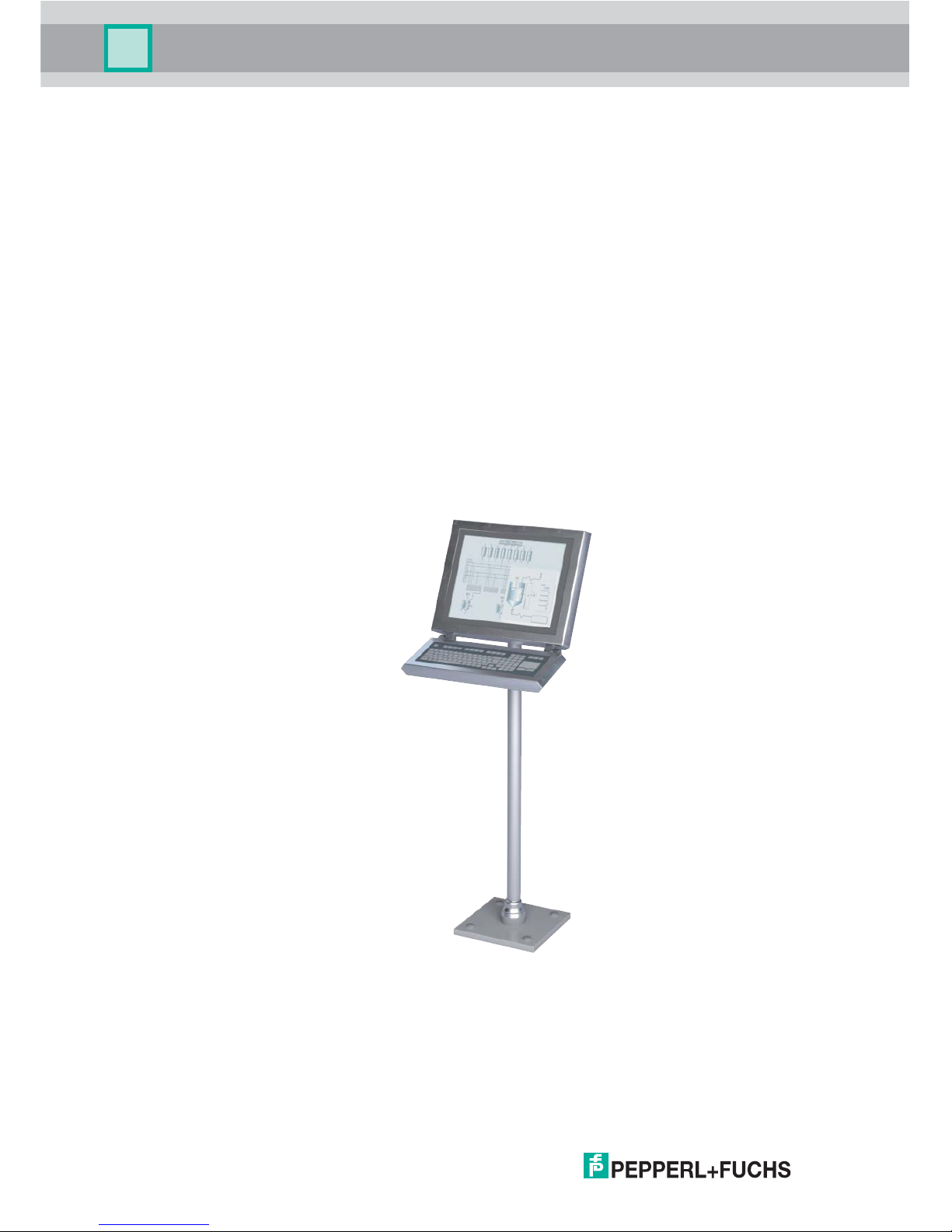
2 Product Specifications
2.1 Overview
GMP (“Good Manufacturing Practice”) is a set of guidelines for assuring the quality of
production processes in controlledindustries and closely follow the guidelines issued by the
European Commission or the FDA in the US. GMP applications are typically used in the
pharmaceutical and food industries. However, products that conform with GMP guidelines
are also required for the manufacture of cosmetics and fragrances or fl avors.
The materials selected, design of the surfaces and architecture of the overall system
should prevent the accumulation of fl uids and dirt. Cleaning, maintenance, inspection and
servicing must be as safe and easy as the processes employed for the disinfection,
pasteurization and sterilization of mechanical components. The VisuNet GMP product
portfolio extends from simple direct monitors and remote monitor systems with Ethernet
connection to a host, to complete PCs available with single or dual monitor systems and
various mounting options. All models feature a 19-inch display with an optional touch
screen. The stainless steel housings have an IP65 degree of protection. Remote monitors
and PCs are equipped with RS232, PS/2, Ethernet and USB interfaces.
The VisuNet GMP product family guarantees a perfect fit for every system infrastructure.
Four models are available depending on the functions required, the display and input unit
and the distance over which the data is transferred. This manual describes the VisuNet
GMP Direct Monitor (DM):
Page 7

VISUNET GMP DM
Product Specifications
219365 2006-06
7
VisuNet GMP DM are direct monitors, which are directly connected to the VGA interface of
the host. Industrial keyboards with integral mouse connected directly to the host are
available as accessories.
Overview of features
• The brilliant display provides high meter-reading comfort
• Easy, user-friendly handling due to optionally available touch screen
• Image position, pixel frequency and phase will be detected and synchronized
automatically
• Rugged stainless steel housing
• Degree of protection IP65
max. 15 m
DM
HOST
Page 8
219365 2006-06
8
VISUNET GMP DM
Product Specifications
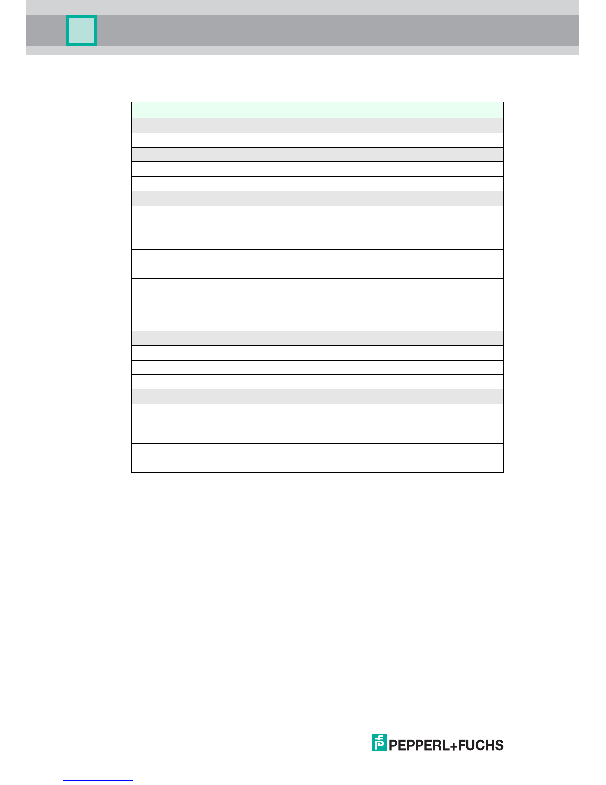
2.2 Technical Data
VisuNet GMP DM
General specifications
Type Direct monitor
Supply
Power supply 20 ... 30 V DC
Power consumption 40 W
Indicators/operating means
Display
Type TFT, LCD, High Color (19 bit)
Screen diagonal 19 ''
Resolution 1280 x 1024 Pixel
Representable colors 16,7 Mio.
Brightness
300 cd/m
2
Input devices Analog resistive touchscreen (optional) ,
Input device combined with keyboard and optional
trackball/touch screen/joystick
Interface
Interface type VGA
Ambient conditions
Ambient temperature 0 ... 50 °C
Mechanical specifications
Protection degree IP65
Installation panel mounting
several mounting devices (rotatable/fix) available
Mass 18 kg
Dimensions 568 mm x 450 mm x 65 mm
Page 9
VISUNET GMP DM
Product Specifications
219365 2006-06
9
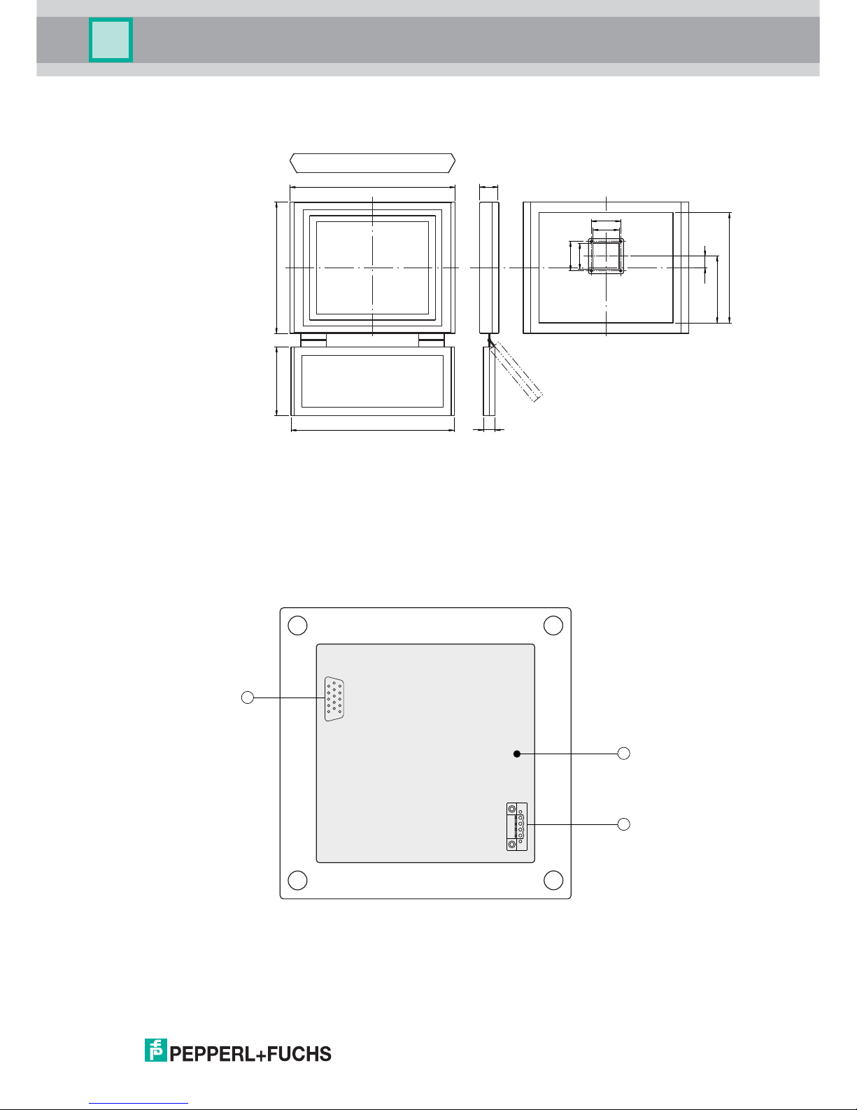
2.3 Dimensions
Figure 2.1: VisuNet GMP model with inclinable keyboard (90°-180°)
2.4 Interfaces and connectionsVisuNet GMP DM
The interfaces and connections of the VisuNet GMP are located within the VESA adapter
at the back of the housing.
The following interfaces are available:
Figure 2.2: VESA adapter at the back of the VisuNet GMP housing
9
10
9
10
228.5
378
39.5
567.8
450
65
235
559
40
A grounding bolt
B Phoenix DFK-MSTB 2,5/ 4-GF-5,08
C VGA interface
B
C
1
4
A
1
6
515
11
Page 10

219365 2006-06
10
VISUNET GMP DM
Product Specifications
Power supply
4-pin socket for power supply connecting (Phoenix Contact DFK-MSTB 2,5/ 4-GF-5,08).
Matching plug: Phoenix Contact MSTBT 2,5/ 4-STF-5,08
VGA interface
15-pin HD-D-Sub socket "VGA" for connecting the monitor to the host.
Picture Pin Signal
1 -
2 -
3 +
4 +
Picture Pin Signal Pin Signal Pin Signal
1 RED 6 RED_GND 11 not used
2 GREEN 7 GREEN_GND 12 IIC-DATA
3 BLUE 8 BLUE_GND 13 HSYNC
4 not used 9 + 5 V 14 VSYNC
5 GND 10 GND 15 IIC-CLOCK
41
1
6
5
15 11
Page 11

VISUNET GMP DM
Product Specifications
219365 2006-06
11
2.5 Accessories
The following accessories are available.
2.5.1 Pedestals
Model number Description
1 Pedestal1-150-1V-KP-G-T-304 Pedestal, turnable 340°, inclination of monitor 10°,
with pipe for keyboard
2 Pedestal1-150-1V-KP-G-F-304 Pedestal, fix mounted, inclination of monitor 10°,
with pipe for keyboard
3 Pedestal1-150-1V-NP-G-T-304 Pedestal, turnable 340°, inclination of monitor 10°,
without pipe for keyboard
4 Pedestal1-150-1V-NP-G-F-304 Pedestal, fix mounted, inclination of monitor 10°,
without pipe for keyboard
5 Pedestal1-130-3V-NP-G-T-304 Pedestal, turnable 340°, inclination of monitor 30°,
without pipe for keyboard on pedestal (shown in
figure with inclinable keyboard at monitor housing,
which is optional available)
6 Pedestal1-130-3V-NP-G-F-304 Pedestal, fix mounted, inclination of monitor 30°,
without pipe for keyboard on pedestal (shown in
figure with inclinable keyboard at monitor housing,
which is optional available)
1 2
3
4 5 6
AAABB B
1500
500
1000
Page 12

219365 2006-06
12
VISUNET GMP DM
Product Specifications
2.5.2 Wall mounting
Model numer Description
1 Wall-Arm1-55-1V-NT-G-*-304 Wall arm, inclination of monitor 10°, without
pipe for keyboard on wall arm (shown in figure
with inclinable keyboard at monitor housing,
which is optional available)
2 models available:
• Wall-Arm1-55-1V-NT-G-F-304: monitor fix
mounted
• Wall-Arm1-55-1V-NT-G-T-304: monitor
turnable
2 Wall-Arm1-55-1V-KT-G-*-304 Wall arm, without inclination of monitor, with
pipe for keyboard
2 models available:
• Wall-Arm 1-55-1V-KT-G-F-304: monitor fix
mounted
• Wall-Arm 1-55-1V-KT-G-T-304: monitor
turnable
3 Wall-Bracket1-0-0V-G-304 Wall bracket
2 31
B B
C
500
Page 13

VISUNET GMP DM
Product Specifications
219365 2006-06
13
2.5.3 Hole drilling templates
Bottom attachment, turnable, fastening at front:
Bottom attachment, fix mounted:
Wall bracket:
129
9
40
A
42-50
90
9
B
Ø
17
280
9
15
105
C
Page 14

VISUNET GMP DM
Product Specifications
219365 2006-06
14
2.5.4 Power supply accessories
Power supply
Model number Description
BN-24/5000-HS-10 Power supply
DATL-A2-2.5-0 Power cable 2x 2.5mm², wire end ferrule, max. length 80 m
DATL-A2-4.0N/2.5F-1 Power cable 2x 4.0mm² +2.5m 2.5mm², wire end ferrule,
length: 110 m
Page 15

VISUNET GMP DM
Installation and Commissioning
219365 2006-06
15
3 Installation and Commissioning
3.1 Preparation
Unpacking the unit
1. Check that all package contents are present and undamaged.
If anything is damaged, inform the shipper and contact the supplier.
2. Check that all items are present and correct based on your order and the shipping
documents.
If you have any questions, please contact Pepperl+Fuchs.
3. Keep the original packing material in case you need to store or ship the unit at a later
time.
3.2 Mounting in the field
VisuNet GMP is licensed for operation in confined spaces.
The cooling of VisuNet GMP does not require active components like CPU fan or water
cooling systems. For that reason there are no ventilation slots in the housing.
To avoid overheating during operation, follow the advices below for field installation:
• Do not expose the VisuNet GMP to direct solar radiation or other heat sources.
• As the heat will dissipate via the housing of the VisuNet GMP, provide sufficient air
circulation.
• Keep the ambient temperature below the specified maximal value.
Mounting the VisuNet GMP
1. If you mount the VisuNet GMP on a pedestal, lead all connection cables from the buttom
up through the pedestal pipe (towards VESA adapter).
2. Lead the connection cables through the VESA adapter.
3. Attach the connection cables to the respective interface.
4. Screw the VisuNet GMP with 4 countersunk head screws (M5) on the VESA adapter at
the back of the housing.
Grounding the VisuNet GMP
Ground the VisuNet GMP via the VESA adapter grounding bolt with the back of the
housing. If you mount the VisuNet GMP on a pedestal, you will be able to use the
grounding bolt with the pedestal.
Note!
The VisuNet GMP is not delivered in sterile condition. Desinfect the device before using it
(spray/wipe disinfectant).
Page 16

219365 2006-06
16
VISUNET GMP DM
Installation and Commissioning
3.3 Commissioning VisuNet GMP RM/PC
Use a low-impandance connection between device and control cabinet.
Use cables with a minimum cross core-section of 2,5 mm
2
.
Turning on the VisuNet GMP
1. Connect the 4-pin plug with the 4-pin power supply socket at the back of the housing.
2. Bolt together the screw plug.
3. Establish the power supply.
After establishing the power supply the VisuNet GMP starts automatically. The LED on
the right hand side of the housing lights green.
Turning off the VisuNet GMP
1. Disconnect the device from the power supply.
2. After that pull out the plug.
Note!
Use the VisuNet GMP only with safety-low voltage (protective extra-low-voltage). The
power supply needs to be in line with applicable standards.
Page 17

VISUNET GMP DM
Operation
219365 2006-06
17
4 Operation
4.1 On Screen Display
VisuNet GMP features a graphical user interface for setting up the display via the On
screen display (OSD menu). A control panel with four buttons for operating the system is
located on the right hand side of the housing.
The following table describes the buttons and their function.
Selecting the OSD menu
To select the OSD menu, press the button.
The OSD menu is divided in the following menu items :
•Audio
• Bright-Contrast
•Color
•Image
•Tools
• Input
• Exit
Bild Taste Funktion Beschreibung
AUTO
adjust
Atuomatic
adjustment
1. Automatic adjustment
2. 2nd click: quit sub menu/menu
MENU/
SELECT
menu access/
selection
1. 1st click: activate the OSD menu
2. Select menu entries
3. Confirm active menu entries
– downwards/
left
1. Navigate in menus: downwards/left
2. Decrease a value
3. shortcut for audio volume
+ upwards/
right
1. Navigate in menus: upwards/right
2. Increase a value
LED Status red light: no signal
green light: operating status "on"
AUTO
adjust
MENU/
SELECT
–
+
MENU/
SELECT
Page 18

219365 2006-06
18
VISUNET GMP DM
Operation
Navigating in the OSD menu
1. If applicable select the OSD menu.
2. Navigate to the designated tab with the button (scroll to the right) and button
(scroll to the left) respectively.
The active tab will be marked.
3. To select a tab, press the button.
The sub menu will be opened.
4. Navigate to the designated sub menu entry with the button and the button
respectively.
5. To select a sub menu entry, press button.
Depending on the menu you will get to another sub menu or to a dialog box.
Adjusting values
1. To adjust values (i.g. brightness or contrast) in a sub menu, press the button and the
button respectively.
2. After adjusting the value, quit the active dialog box by pressing the button.
The adjusted value will be adopted and you will return to the designated sub menu.
Quitting OSD menu/sub menus
1. To quit a sub menu, select the menu item .
2. Confirm the selection by pressing the button.
The sub menu will be quit.
+ –
MENU/
SELECT
+ –
MENU/
SELECT
+
–
AUTO
adjust
MENU/
SELECT
Page 19

VISUNET GMP DM
Operation
219365 2006-06
19
4.1.1 Audio menu
Menu item Name Description
Volume Change the volume
Mute Mute the audio
Exit Quit the sub menu and return to the menu one lever
higher.
Note!
The VisuNet GMP has no audio speaker.
Page 20

219365 2006-06
20
VISUNET GMP DM
Operation
4.1.2 Bright-Contrast menu
Menu Item Name Description
Brightness Decrease/increase brightness
Contrast Decrease/increase contrast
Exit Quit the sub menu and return to the menu one lever
higher.
Page 21

VISUNET GMP DM
Operation
219365 2006-06
21
4.1.3 Color menu
Menu item Name Description
Color Auto Automatic adjustment of color
Color Temperature Adjustment of color temperature. Choose between
2 default settings (9300 K; 6500 K) in the sub menu
or create your own color settings.
Exit Quit the sub menu and return to the menu one lever
higher.
Page 22

219365 2006-06
22
VISUNET GMP DM
Operation
4.1.4 Image menu
Menu item Name Description
Image Auto Automatic adjustment of image position and width.
Width Adjust the image width
Phase Adjust the phase. Changes effect the display
sharpness
Horizontal Scroll the display to the right and to the left
respectively
Vertical Scroll the display upwards and downwards
respectively
Display Mode Choose between 6:10 or 4:3 format in this sub menu
Exit Quit the sub menu and return to the menu one lever
higher
Page 23

VISUNET GMP DM
Operation
219365 2006-06
23
4.1.5 Tools menu
Menu item Name Description
OSD Select more sub menus: time, horizontal, vertical, OSD
menu direction, exit
Reset Reset to factory settings
Sharpness Change sharpness
Language Change language of OSD menu
Exit Quit the sub menu and return to the menu one lever
higher.
A
A
A
Page 24

219365 2006-06
24
VISUNET GMP DM
Operation
4.1.6 Input menu
Menu item Name Description
VGA Activate VGA interface
DVI Activate DVI interface
Exit Quit the sub menu and return to the menu one lever
higher
1
2
Page 25

VISUNET GMP DM
Operation
219365 2006-06
25
4.1.7 Exit menu
Page 26

219365 2006-06
26
VISUNET GMP DM
Appendix
5 Appendix
5.1 How to contact Pepperl+Fuchs GmbH
Should you encounter any problems with the device, please consult the technical manual
first of all. If you are still anable to solve the problems after studying the above information
carefully you can contact the following places:
If you need to contact the support hotline, please make sure you have the Technical
manual handy!
Region Phone / mail address
Western Europe and South Africa
France, Belgium, Netherlands, Luxemburg,
South Africa
+33-1 60 92 13-13
commercial@fr.pepperl-fuchs.com
Northern Europe
Great Britain, Sweden, Norway, Denmark +44-161-633 6431
sales@gb.pepperl-fuchs.com
Ireland +353-21-4883798
info@insteco.iol.ie
Finnland +358-9-477720-0
joel.patrikka@sensonor.fi
Southern Europe
Italy, Spain, Greece, Switzerland, Israel +39-039 6292-1 ,
info@it.pepperl-fuchs.com
Eastern Europe
Russia, Austria, Czech Rep., Hungary,
Poland, Croatia, Slovenia, Turkey,
Romania
+39-039 6292-1
info@it.pepperl-fuchs.com
Germany +49-621-776-3712
support_hmi@de.pepperl-fuchs.com
Northern America
USA, Canada, Mexiko +1-330-486-0002
sales@us.pepperl-fuchs.com
Southern America
Brasil, Chile, Middle-America +55-11-4339-9935
vendas@br.pepperl-fuchs.com
Argentinia +54-11-4730 1100
schillig@schillig.com.ar
Middle East / India
Dubai, UA, Kuwait, Pakistan, Iran, Irak 971-4-8838378
info@ae.pepperl-fuchs.com
India +91-80 2837-8030
pa-info@in.pepperl-fuchs.com.
Asia-Pacific
Australia, Singapore, China, Thailand, ... +65-6779-9091
sales@sg.pepperl-fuchs.com
Japan +81-45-939 7802
sales@jp.pepperl-fuchs.com
Page 27

Subject to modifications
Copyright PEPPERL+FUCHS • Printed in Germany
www.pepperl-fuchs.com
Worldwide Headquarters
Pepperl+Fuchs GmbH
68307 Mannheim · Germany
Tel. +49 621 776-0
E-mail: info@de.pepperl-fuchs.com
For the Pepperl+Fuchs representative
closest to you check www.pepperl-fuchs.com/pfcontact
PROCESS AUTOMATION –
PROTECTING YOUR PROCESS
219365 / TDOCT-1800_ENG
06/2006
 Loading...