

Pepperl+Fuchs VDM18-100/20/122/151, VDM18-100/20/88/122/151, VDM18-300/20/122/151, VDM18-300/20/88/122/151, VDM18-300/21/122/151 User Manual
FACTORY AUTOMATION
HANDBUCH / MANUAL / MANUEL
VDM18-100/20/122/151
VDM18-100/20/88/122/151
VDM18-300/20/122/151
VDM18-300/20/88/122/151
VDM18-300/21/122/151

Copyright (Deutsch)
Die Wiedergabe bzw. der Nachdruck dieses Dokuments, sowie die entsprechende Speicherung in Datenbanken
und Abrufsystemen bzw. die Veröffentlichung, in jeglicher Form, auch auszugsweise, oder die Nachahmung
der Abbildungen, Zeichnungen und Gestaltung ist nur auf Grundlage einer vorherigen, in schriftlicher Form vorliegenden Genehmigung seitens Pepperl+Fuchs GmbH, zulässig.
Für Druckfehler und Irrtümer, die bei der Erstellung der Betriebsanleitung unterlaufen sind, ist jede Haftung
ausgeschlossen. Liefermöglichkeiten und technische Änderungen vorbehalten.
Erstveröffentlichung August 2004.
Copyright (Englisch)
No part of this document may be reproduced, published or stored in information retrieval systems or data bases
in any manner whatsoever, nor may illustrations, drawings and the layout be copied without prior written permission from Pepperl+Fuchs GmbH.
We accept no responsibility for printing errors and mistakes which occurred in drafting this manual. Subject to
delivery and technical alterations.
First publication August 2004
Copyright (Français)
Toute reproduction de ce document, ainsi que son enregistrement dans une base ou système de données ou
sa publication, sous quelque forme que ce soit, même par extraits, ainsi que la contrefaçon des dessins et de la
mise en page ne sont pas permises sans l’autorisation explicite et écrite de Pepperl+Fuchs GmbH.
Nous déclinons toute responsabilité concernent les fautes éventuelles d’impression et autres erreurs qui
auraient pu intervenir lors du montage de cette brochure. Sous réserve de modifi cations techniques et de
disponibilité pour livraison.
Première publication Août 2004
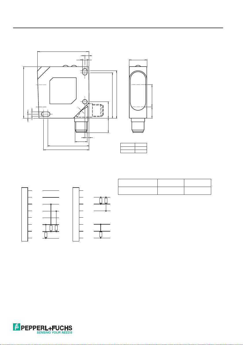
Maßzeichnung / Dimensional drawing / Plan coté
50
50
4.3
4
40
44
4.3
M12 x 1
4
4
Abb. 1 / Illustr. 1 / Fig. 1
Anschluss / Wiring / Raccordement
Option /20 - 2 x PNP Option /21 - 2 x NPN
n.c.
1
2
+UB
Q1
3
Q2
4
n.c.
5
Analog +
6
0 V
7
Analog -
8
n.c.
1
2
+UB
Q1
3
Q2
4
n.c.
5
Analog +
6
0 V
7
Analog -
8
17
Receiver
18
13.5
46
44
Version X (mm)
VDM18-100 18.4
VDM18-300 21.5
X11
Emitter
Typ / Type / Ref. Pin 1 Pin 5
VDM18 .../88 RS485 Y/A RS485 Z/B
Abb. 2 / Illustr. 2 / Fig. 2
3

Inhalt / Content / Contenu
Deutsch ................................................................................................................... 5
English ................................................................................................................... 26
Français ................................................................................................................. 47
4

Mounting and
operating instructions
Content
Signs and Symbols ......................................................................................................................................26
Safety information .......................................................................................................................................26
Appropriate use ...........................................................................................................................................27
Performance characteristics ........................................................................................................................27
Mode of function ..........................................................................................................................................27
Mounting ......................................................................................................................................................28
Electrical installation ...................................................................................................................................29
Instructions of use .......................................................................................................................................30
General use .................................................................................................................................................30
Settings........................................................................................................................................................32
Functions .....................................................................................................................................................32
Reset ...........................................................................................................................................................34
Unlocking keys ............................................................................................................................................34
Averaging ....................................................................................................................................................35
Automatic zero mode...................................................................................................................................35
Automatic centre mode................................................................................................................................36
Maximum hold mode ...................................................................................................................................36
Difference hold mode ..................................................................................................................................37
Measured value hold mode .........................................................................................................................37
Differential measurement mode ..................................................................................................................38
Transmission protocol .................................................................................................................................40
Bus commands ............................................................................................................................................41
Explanations on bus commands..................................................................................................................42
Optical data (typ.) ........................................................................................................................................43
Electrical data (typ.), ....................................................................................................................................43
Mechanical data ..........................................................................................................................................43
Order information.........................................................................................................................................44
26
Date of issue: 08/08/2011 Partnummer: 194551
Mounting and
operating instructions
Signs and Symbols
Warning
This symbol signals passages in the manual which must be observed at all times. Non-compliance can
cause injuries or material damage.
Warning Laser
This symbol appears in front of warning passages concerning the danger of laser beams.
Information
This symbol signals passages with useful information.
Safety information
It is essential that this manual, and the safety information in particular, is read, thoroughly understood and observed before setting the VDM18 sensor into operation.
The VDM18 sensor may only be connected, mounted and adjusted by qualifi ed personnel.
Interventions and alterations to the device are not permissible!
The VDM18 sensor is not a safety component as described by EU machine directives and must
never be used in applications where human safety is at risk.
The VDM18 sensor complies with laser protection class 2 according to DIN EN 60825-1, status
2008-05. The technical requirements comply with EN 60947-5-2, 2000 edition.
Never look into the path of the laser. Do not suppress the refl ex to close the eyelids.
Gazing into the beam path for longer periods can damage the retina of the eye.
When mounting the sensor, ensure if possible that the beam path is sealed off at the end. The
laser must not be directed at people (head height). When aligning VDM18, ensure that there are
no refl ections on refl ective surfaces.
Should the safety label on the VDM18 sensor be partly covered due to its installation position,
other safety labels are to be positioned on visible parts of the sensor. When applying the new
safety label, make sure that you cannot look into the laser beam whilst reading it.
Date of issue: 08/08/2011 Partnummer: 194551
27
Mounting and
operating instructions
Appropriate use
The VDM18 sensor is not authorised for use in protecting human safety on machines and during
technical applications.
The VDM18 is an optical sensor and measures distances without contact. When combined with another VDM18
sensor, the thickness of objects can also be measured.
Performance characteristics
• Operating range VDM18-100: 30 – 100 mm
• Operating range VDM18-300: 80 – 300 mm
• 2 digital outputs
• Analogue output 4-20 mA
• Compact design 50 x 50 x 17 mm
• High resolution (0.1 % of measuring range)
• Option /88 with serial bus interface (RS 485 half-duplex)
• “Teach-in” settings also possible per software
• Wide functional range
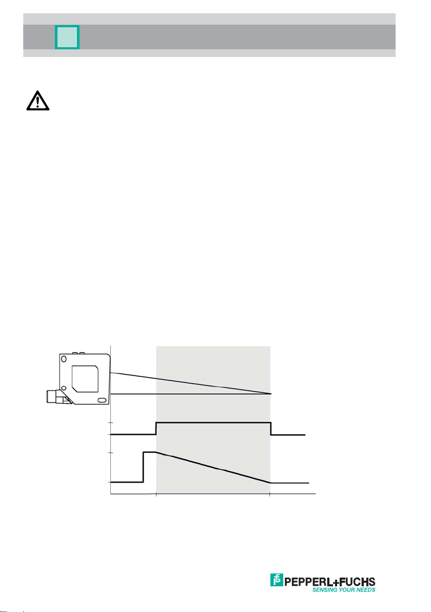
Mode of function
The VDM18 sensor measures according to the principle of triangulation. The distance between the object and sensor
is determined on the basis of the position of the light spot on the detector.
Operating range (Factory setting)
On
Off
20 mA
4 mA
Illustr. 3
28
OK LED (green)
(Good Target)
Analogue
output
(invertible)
VDM18-100 ...
VDM18-300 ...
30 mm
80 mm
100 mm
300 mm
Date of issue: 08/08/2011 Partnummer: 194551
Mounting and
operating instructions
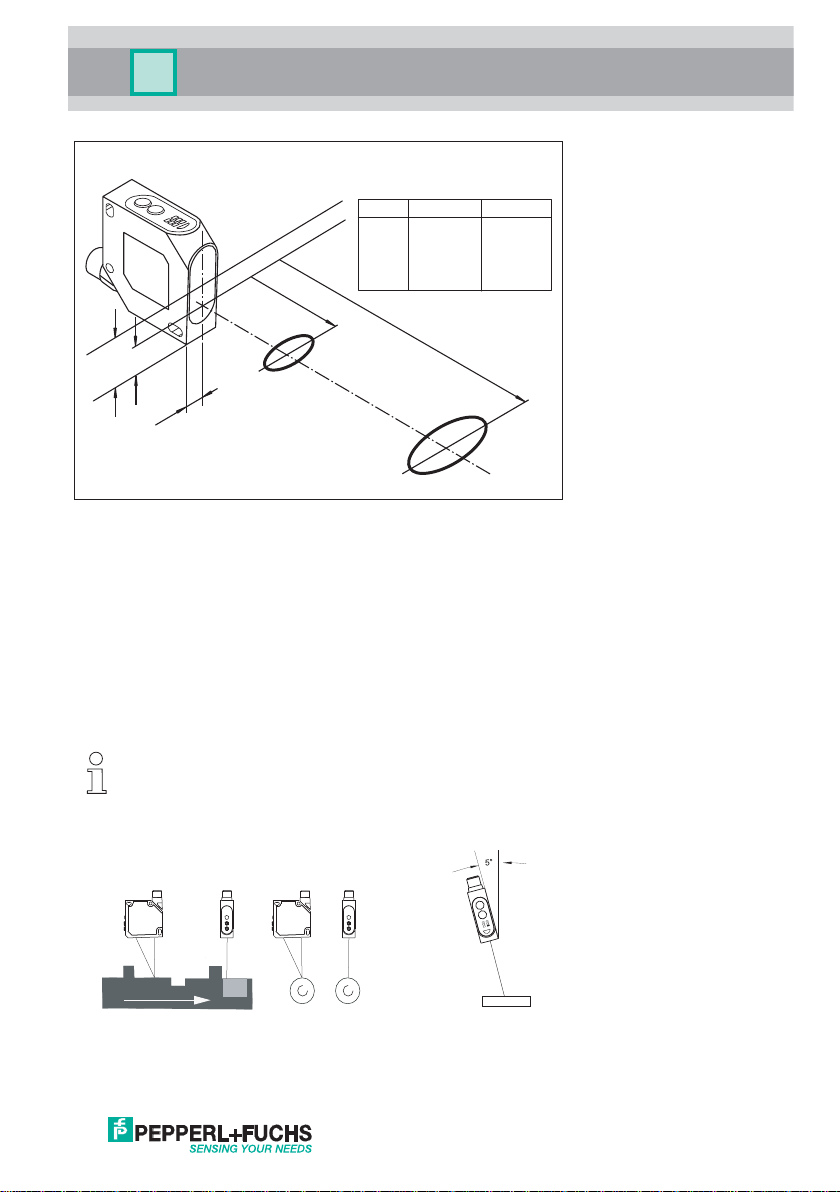
Light spot representation
VDM18-100 VDM18-300
C (mm)
D (mm)
E (mm)
1.5 x 3 1.5 x 3.5
1.5 x 3.25 2 x 4.5
B
D
30A (mm) 80
100B (mm) 300
29.4 32.5
Illustr. 4
Receiver
Emitter
A
11
E
8.5
C
Mounting
Sensor alignment
Position VDM18 in a way that the distance to the object is within the working range of the sensor.
Screw the VDM18 sensor to the mounting bracket, e.g. type OMH-VDM18 (not included in delivery) or a suitable
device. Only use the holes provided in the housing (see dimensioned drawing) for this purpose.
If steps, moving or striped objects are to be detected, the front panel of the sensor should be mounted at a right
angle to the direction of movement or stripes (Illustr. 5 + 6).
With very refl ective objects, the sensor must be mounted at an angle of approx. 5° (Illustr. 7).
To optimise measurements, the VDM18 sensor is to be given constructive protection from vibrations.
The VDM18 sensor is now mounted.
Z
Illustr. 5 Linear movement
Date of issue: 08/08/2011 Partnummer: 194551
Z
Illustr. 6 Rotating movement
Illustr. 7 Refl ective object
29
 Loading...