

Pepperl+Fuchs VDM18-100/20/122/151, VDM18-100/20/88/122/151, VDM18-300/20/122/151, VDM18-300/20/88/122/151, VDM18-300/21/122/151 User Manual
Page 1
FACTORY AUTOMATION
HANDBUCH / MANUAL / MANUEL
VDM18-100/20/122/151
VDM18-100/20/88/122/151
VDM18-300/20/122/151
VDM18-300/20/88/122/151
VDM18-300/21/122/151
Page 2

Copyright (Deutsch)
Die Wiedergabe bzw. der Nachdruck dieses Dokuments, sowie die entsprechende Speicherung in Datenbanken
und Abrufsystemen bzw. die Veröffentlichung, in jeglicher Form, auch auszugsweise, oder die Nachahmung
der Abbildungen, Zeichnungen und Gestaltung ist nur auf Grundlage einer vorherigen, in schriftlicher Form vorliegenden Genehmigung seitens Pepperl+Fuchs GmbH, zulässig.
Für Druckfehler und Irrtümer, die bei der Erstellung der Betriebsanleitung unterlaufen sind, ist jede Haftung
ausgeschlossen. Liefermöglichkeiten und technische Änderungen vorbehalten.
Erstveröffentlichung August 2004.
Copyright (Englisch)
No part of this document may be reproduced, published or stored in information retrieval systems or data bases
in any manner whatsoever, nor may illustrations, drawings and the layout be copied without prior written permission from Pepperl+Fuchs GmbH.
We accept no responsibility for printing errors and mistakes which occurred in drafting this manual. Subject to
delivery and technical alterations.
First publication August 2004
Copyright (Français)
Toute reproduction de ce document, ainsi que son enregistrement dans une base ou système de données ou
sa publication, sous quelque forme que ce soit, même par extraits, ainsi que la contrefaçon des dessins et de la
mise en page ne sont pas permises sans l’autorisation explicite et écrite de Pepperl+Fuchs GmbH.
Nous déclinons toute responsabilité concernent les fautes éventuelles d’impression et autres erreurs qui
auraient pu intervenir lors du montage de cette brochure. Sous réserve de modifi cations techniques et de
disponibilité pour livraison.
Première publication Août 2004
Page 3
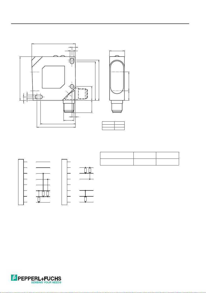
Maßzeichnung / Dimensional drawing / Plan coté
50
50
4.3
4
40
44
4.3
M12 x 1
4
4
Abb. 1 / Illustr. 1 / Fig. 1
Anschluss / Wiring / Raccordement
Option /20 - 2 x PNP Option /21 - 2 x NPN
n.c.
1
2
+UB
Q1
3
Q2
4
n.c.
5
Analog +
6
0 V
7
Analog -
8
n.c.
1
2
+UB
Q1
3
Q2
4
n.c.
5
Analog +
6
0 V
7
Analog -
8
17
Receiver
18
13.5
46
44
Version X (mm)
VDM18-100 18.4
VDM18-300 21.5
X11
Emitter
Typ / Type / Ref. Pin 1 Pin 5
VDM18 .../88 RS485 Y/A RS485 Z/B
Abb. 2 / Illustr. 2 / Fig. 2
3
Page 4

Inhalt / Content / Contenu
Deutsch ................................................................................................................... 5
English ................................................................................................................... 26
Français ................................................................................................................. 47
4
Page 5

Mounting and
operating instructions
Content
Signs and Symbols ......................................................................................................................................26
Safety information .......................................................................................................................................26
Appropriate use ...........................................................................................................................................27
Performance characteristics ........................................................................................................................27
Mode of function ..........................................................................................................................................27
Mounting ......................................................................................................................................................28
Electrical installation ...................................................................................................................................29
Instructions of use .......................................................................................................................................30
General use .................................................................................................................................................30
Settings........................................................................................................................................................32
Functions .....................................................................................................................................................32
Reset ...........................................................................................................................................................34
Unlocking keys ............................................................................................................................................34
Averaging ....................................................................................................................................................35
Automatic zero mode...................................................................................................................................35
Automatic centre mode................................................................................................................................36
Maximum hold mode ...................................................................................................................................36
Difference hold mode ..................................................................................................................................37
Measured value hold mode .........................................................................................................................37
Differential measurement mode ..................................................................................................................38
Transmission protocol .................................................................................................................................40
Bus commands ............................................................................................................................................41
Explanations on bus commands..................................................................................................................42
Optical data (typ.) ........................................................................................................................................43
Electrical data (typ.), ....................................................................................................................................43
Mechanical data ..........................................................................................................................................43
Order information.........................................................................................................................................44
26
Date of issue: 08/08/2011 Partnummer: 194551
Page 6
Mounting and
operating instructions
Signs and Symbols
Warning
This symbol signals passages in the manual which must be observed at all times. Non-compliance can
cause injuries or material damage.
Warning Laser
This symbol appears in front of warning passages concerning the danger of laser beams.
Information
This symbol signals passages with useful information.
Safety information
It is essential that this manual, and the safety information in particular, is read, thoroughly understood and observed before setting the VDM18 sensor into operation.
The VDM18 sensor may only be connected, mounted and adjusted by qualifi ed personnel.
Interventions and alterations to the device are not permissible!
The VDM18 sensor is not a safety component as described by EU machine directives and must
never be used in applications where human safety is at risk.
The VDM18 sensor complies with laser protection class 2 according to DIN EN 60825-1, status
2008-05. The technical requirements comply with EN 60947-5-2, 2000 edition.
Never look into the path of the laser. Do not suppress the refl ex to close the eyelids.
Gazing into the beam path for longer periods can damage the retina of the eye.
When mounting the sensor, ensure if possible that the beam path is sealed off at the end. The
laser must not be directed at people (head height). When aligning VDM18, ensure that there are
no refl ections on refl ective surfaces.
Should the safety label on the VDM18 sensor be partly covered due to its installation position,
other safety labels are to be positioned on visible parts of the sensor. When applying the new
safety label, make sure that you cannot look into the laser beam whilst reading it.
Date of issue: 08/08/2011 Partnummer: 194551
27
Page 7
Mounting and
operating instructions
Appropriate use
The VDM18 sensor is not authorised for use in protecting human safety on machines and during
technical applications.
The VDM18 is an optical sensor and measures distances without contact. When combined with another VDM18
sensor, the thickness of objects can also be measured.
Performance characteristics
• Operating range VDM18-100: 30 – 100 mm
• Operating range VDM18-300: 80 – 300 mm
• 2 digital outputs
• Analogue output 4-20 mA
• Compact design 50 x 50 x 17 mm
• High resolution (0.1 % of measuring range)
• Option /88 with serial bus interface (RS 485 half-duplex)
• “Teach-in” settings also possible per software
• Wide functional range
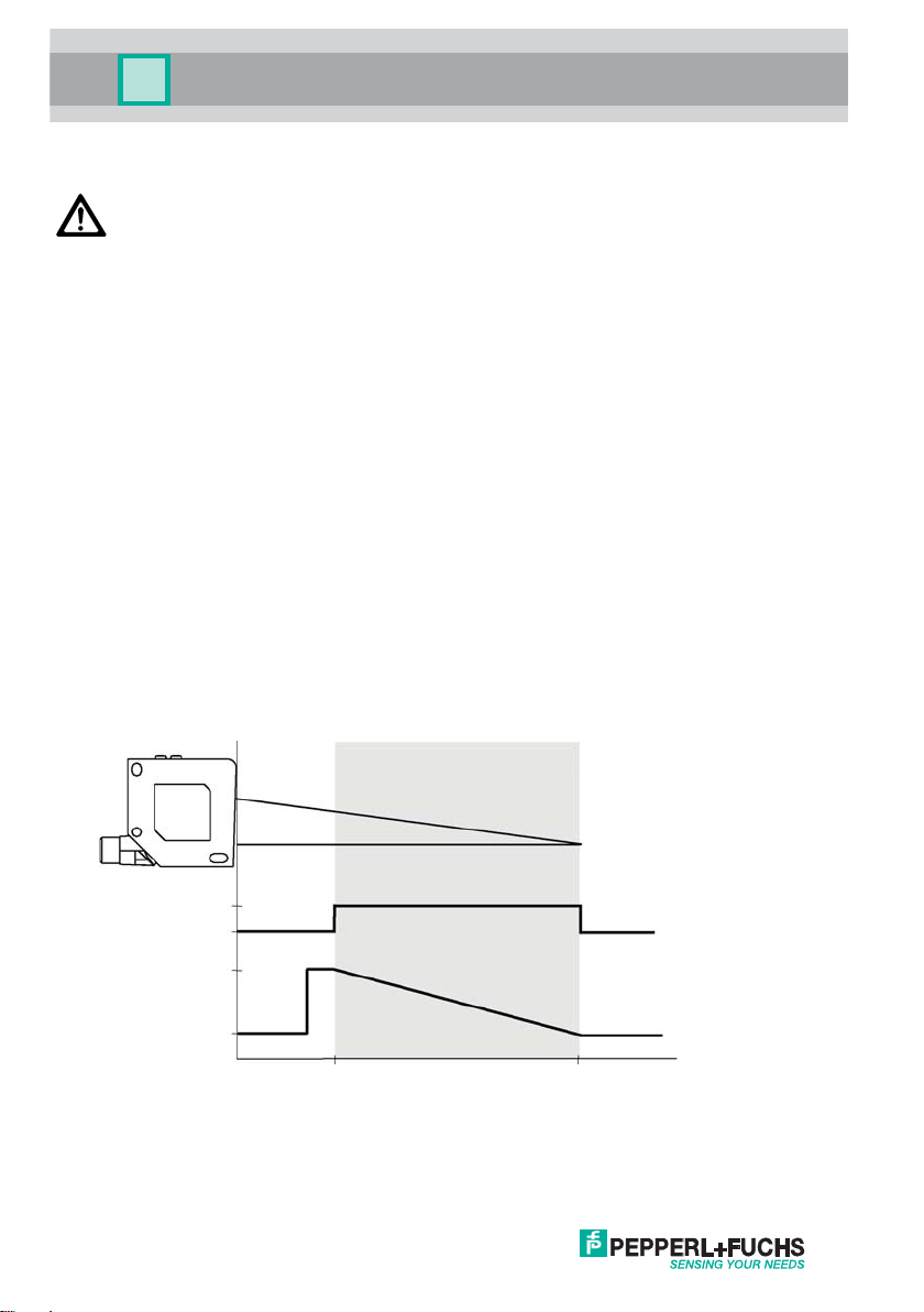
Mode of function
The VDM18 sensor measures according to the principle of triangulation. The distance between the object and sensor
is determined on the basis of the position of the light spot on the detector.
Operating range (Factory setting)
On
Off
20 mA
4 mA
Illustr. 3
28
OK LED (green)
(Good Target)
Analogue
output
(invertible)
VDM18-100 ...
VDM18-300 ...
30 mm
80 mm
100 mm
300 mm
Date of issue: 08/08/2011 Partnummer: 194551
Page 8
Mounting and
operating instructions
Light spot representation
VDM18-100 VDM18-300
C (mm)
D (mm)
E (mm)
1.5 x 3 1.5 x 3.5
1.5 x 3.25 2 x 4.5
B
D
30A (mm) 80
100B (mm) 300
29.4 32.5
Illustr. 4
Receiver
Emitter
A
11
E
8.5
C
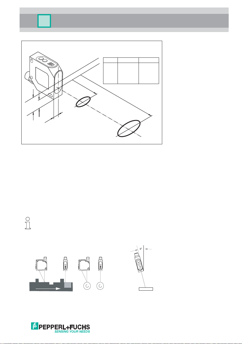
Mounting
Sensor alignment
Position VDM18 in a way that the distance to the object is within the working range of the sensor.
Screw the VDM18 sensor to the mounting bracket, e.g. type OMH-VDM18 (not included in delivery) or a suitable
device. Only use the holes provided in the housing (see dimensioned drawing) for this purpose.
If steps, moving or striped objects are to be detected, the front panel of the sensor should be mounted at a right
angle to the direction of movement or stripes (Illustr. 5 + 6).
With very refl ective objects, the sensor must be mounted at an angle of approx. 5° (Illustr. 7).
To optimise measurements, the VDM18 sensor is to be given constructive protection from vibrations.
The VDM18 sensor is now mounted.
Z
Illustr. 5 Linear movement
Date of issue: 08/08/2011 Partnummer: 194551
Z
Illustr. 6 Rotating movement
Illustr. 7 Refl ective object
29
Page 9

Mounting and
operating instructions
Electrical installation
Warning: Pin 1 and pin 5 must not be connected to operational voltage as this will destroy the
VDM18 sensor.
Turn the sensor connector plug according to the installation position (Illustr. 1) so that the connection cable can be
freely connected without being bent.
Insert the socket of the connection cable into the VDM18 connector and screw tight
For example, secure the connection cable from sliding with a cable tie .
Connect VDM18 as shown in Illustr. 8
Option /20 - 2 x PNP Option /21 - 2 x NPN
n.c.
1
2
+UB
Q1
3
Q2
4
n.c.
5
Analog +
6
0 V
7
Analog -
8
n.c.
1
2
+UB
Q1
3
Q2
4
n.c.
5
Analog +
6
0 V
7
Analog -
8
Illustr. 8 Connection diagram
Connection Colour Use Comments
1 (WH) White RS485 Y/A /88 option only
2 (BN) Brown + U
B
3 (GN) Green As signal output Q1 or input with optional input functions (see
“Settings” page 32)
4 (YE) Yellow As signal output Q2 or switching function “good target” (detec-
table object in measuring range)
5 (GY) Grey RS 485 Z/B /88 option only
6 (PK) Pink Q
7 (BU) Blue - U
A + analogue measurement
B
8 (RD) Red QA - analogue mass
Type Pin 1 Pin 5
VDM18 .../88 RS485 Y/A RS485 Z/B
Q1
Q2 or good target
Once power supply has been connected, the VDM18 is ready for operation after a short stand-by delay
(< 300 ms).
For maximum precision, please allow for a heating period (approx. 5 minutes).
30
Date of issue: 08/08/2011 Partnummer: 194551
Page 10

Mounting and
operating instructions
Instructions of use
Control panel
The VDM18 has various modes and is confi gured using the S and T buttons.
Button
S
Set button: Change / confi rm a setting or set a switching point
T
Toggle button: Select a function (proceed to the next function)
The selected settings and signal condition are indicated by LEDs.
S
T
ZA
LED Colour Use/Description
BA Green Power supply indicator
Q2
ZA Red Status indicator
1 Yellow Q1 input/output
Q
2 Yellow Q2 input/output
Q
H Green Q
OK Green Good target (object detected and in measuring range)
T Green Pulse stretching function is active
Z Green Q
On: ready (run mode)
Flashing: setting mode is active
Function activated/not activated, or confi rmation signal
1 trigger input or Q1 enable input function active
1 automatic centre or Q1 automatic zero function is active
1, Q2, H, OK, T and Z
BA
Q1
H OK
T Z
Illustr. 9
The table of functions on page 32 explains the further signifi cance of the LEDs: Q
General use
The following four steps are used to confi gure the VDM18 sensor:
1. Activate setting mode
Press the S and T buttons simultaneously for 3 seconds
After this period, the power supply indicator BA fl ashes
set VDM18, see Illustr. 9. The LEDs show the status of function no. 1 (page 32)
When all the LEDs start immediately fl ashing
Unlock VDM18, see paragraph “Unlocking keys” on page 34
2. Select functions (see page 32)
Press the T button to select the next function in the function table.
The function number is indicated by a clear LED pattern and the function status is indicated by the status indicator ZA
(LED on = active, LED off = not active).
The sensor only switches to the next function when the T button is released.
Date of issue: 08/08/2011 Partnummer: 194551
31
Page 11

Mounting and
operating instructions
If no change occurs:
Press T button for longer
The fi rst function follows the last available function.
If the wrong function is selected by mistake, it is not possible to jump directly back to the previous function number.
Press the T button several times until the required function reappears.
Or deactivate setting mode (see point 4) and repeat procedure from step 1.
3. Setting the function status
Press the S button to alter the status of a particular function. The status indicator alters according to the table of
functions. Settings are immediately effective but must still be saved as described in point 4.
Should the status indicator not alter or not light up whilst S is pressed
Check the position of the VDM18 sensor in relation to the measuring range and adapt if necessary
To reset the setting, press the S button once again (is not valid when transferring measured value as switching point!)
4. Deactivate setting mode
First press the T button and then simultaneously press the S button. All settings are then saved. Once the S button is
released, the sensor is in run mode. The BA power supply indicator is permanently alight.
Should the power supply fail during the setting procedure, all settings are lost.
32
Date of issue: 08/08/2011 Partnummer: 194551
Page 12

Mounting and
operating instructions
Settings
The VDM18 sensor can be confi gured as follows with functions 1 to 26 in setting mode (teach-in).
Button
S
Set button: Change / confi rm a setting or set a switching point
T
Toggle button: Select a function (proceed to the next function)
Functions
No. LED Muster Description “ZA” status indicator Factory setting
1
Select Q1 output mode. On = Q1 is a signal output
Off = Q1 is not a signal output
On
2
3 Scanning zone: Transfer of current meas.
4
5
6
7
8
9
10
Transfer of current meas. value as 1st
switching point of Q1. signal output.
value as 2nd switching point of Q1 signal
output. Q1 must be signal output (see
function no 1).
N.C./N.O. change-over of switching
functions for Q1.
Q2 output mode. On = Q2 is a signal output
Transfer of current meas. value as 1st
switching point of Q2 signal output.
Q2 must be signal output (see function
no 5)
Scanning zone: Transfer of current meas.
value as 2nd switching point of Q2 signal
output. Q2 must be signal output (see
function no 5).
N.C./N.O. change-over of switching
functions for Q2.
Pulse stretching of Q1 and Q2 by 50 ms. On = Pulse stretching on
Q2 signal output shows status “good
target”. Switching signal can be inverted
with function no 8.
On* = Measured value valid
Off* = Measured value invalid
On = Measured value valid
Off = Measured value invalid
On = N.C.
Off = N.O.
Off = Q2 displays good target
On* = Measured value valid
Off *= Measured value invalid
On = Measured value valid
Off = Measured value invalid
On = N.C.
Off = N.O.
Off = Pulse stretching off
On = Object within...
Off = Object outside...
...measuring range
Half measuring
range
Off
N.O.
Off
Good Target
Off
N.O.
Off
On
* as long as the S button is pressed
Date of issue: 08/08/2011 Partnummer: 194551
33
Page 13

Mounting and
operating instructions
No. LED Muster Description “ZA” status indicator Factory setting
11
12
13
14
15
16
17 Set analogue output 100% (20 mA): When
Q1 trigger input mode:
With rising edge on Q1, measured value is
held until the next trigger occurs.
Q1 enable input mode:
Used to switch laser beam on and off.
Laser beam is on when Q1 = +UB. If Q1
= - UB, the laser beam is switched off.
Last measured value remains. When reactivated, the response time is prolonged
according to the set mean value.
Switches off averaging:
The fi rst measured value is taken into
account (page 35).
Switches on 4 ms averaging:
the fi rst 10 meas. values are taken into
account (page 35).
Switches on 40 ms averaging:
all (max. 100) meas. values are taken into
account (page 35).
Set analogue output 0% (4 mA):
When S button is activated, the current
meas. value corresponds with 0% value of
the analogue output.
S button is activated, the current meas.
value corresponds with 100% value of the
analogue output.
On = Q1 is a trigger input
Off = Q1 is not a trigger input
On = active
Off = not active
On = Averaging off On
On = active
Off = not active
On = active
Off = not active
On* = Object within…
Off* = Object outside...
...measuring range
On* = Object within…
Off* = Object outside...
...measuring range
Off
Off
Off
Off
0% = 4 mA = end
of meas. range
100% = 20 mA
= start of meas.
range
18
19
* as long as the S button is pressed
34
Q1 automatic zero mode:
For characteristic curve displacement. If
Q1 = +UB, the current measuring signal
is set to the analogue value 0 % = 4 mA.
The incline of the characteristic curve is
maintained. If exceeded, the characteristic curve ends at the start or end of the
measuring range.
Q1 automatic centre mode: displacement
of centre of characteristic curve. If Q1 =
+UB, the current measuring signal is set to
the analogue value
50 % = 12 mA. The incline of the characteristic curve is maintained. If exceeded,
the characteristic curve ends at the start
or end of the measuring range.
On = Automatic zero active
Off = Autommatic zero not active
On = Automatic centre active
Off = Automatic centre not
active
Not active
Not active
Date of issue: 08/08/2011 Partnummer: 194551
Page 14

Mounting and
operating instructions
No. LED Muster Description “ZA” status indicator Factory setting
20
21
22
Q1 maximum hold mode:
Provided
1 = +UB, the max. recorded measured
Q
value is stored.
If Q1 = -UB, the determined value is transmitted at the analogue output. A minimum
hold can be set by inverting the analogue
characteristic curve (analogue 100% point
< analogue
0 % point).
Q1 difference hold mode:
Provided Q1 = +UB, the difference
between the measured values is saved.
When Q1 = -UB, the determined value is
transmitted at the analogue output.
Activate factory settings:
When the S button is pressed, the factory
setting is activated.
On = Maximum hold active
Off = Maximum hold not active
On = Difference hold active
Off = Difference hold not active
ZA lights up as long as the S button
is pressed
Not active
Not active
Not active
23
24 Meas. value hold mode:
25
26
Locking keys:
If function is activated locking becomes
active once the setting mode has been
quit. Cancel locking with RESET or the
unlocking function (see “Unlocking keys”)
If no object is in the measuring range
(good target = off), the last meas. value is
held at the analogue output.
Differential measurement mode master:
Activate/deactivate (option /88 only)
Description see differential measurement
mode (page 38).
Differential measurement mode slave:
Activate/deactivate (option /88 only)
Description see differential measurement
mode (page 38).
Reset
When switching on the sensor (power on), keep the S button pressed (approx. 10 seconds) until the
LED lights stop fl ashing and are permanently on. The BA power supply indicator is green. When the
S button is released, a Reset is carried out which returns the VDM18 to delivery status where factory
settings are active.
(See table of functions page 32-34).
Unlocking keys
When switching on the sensor (power on), keep the T button pressed (approx. 10 seconds) until the
LED lights stop fl ashing and are permanently on. The ZA status indicator is red. When the T button is
released, the setting mode is unlocked.
On = Locking is active
Off = Locking is not active
On = Meas. value hold is active
Off = Meas. value hold is
not active
On = Differential measurement
mode - master is active
Off = Differential measurement
mode - master is not active
On = Differential measurement
mode - slave is active
Off = Differential measurement
mode - slave is not active
Not active
Not active
Not active
Not active
Date of issue: 08/08/2011 Partnummer: 194551
35
Page 15

Mounting and
operating instructions
Averaging
The measuring result (output signal) is smoothed by averaging. The measured values are read continuously into a
memory and the arithmetical mean is formed. Functions 14 and 15 (page 33) determine the number of measurements (10 or 100) to be used for averaging.
With a scanning rate of 0.4 ms per measurement, the response time lies between 0.4 ms (without averaging) and 40
ms.
Example of use: When measuring rough surfaces, it is possible to counter-balance fl uctuations in measured values.
Measuring object
Response time
I(mA)
Direction of movement
0.4 ms = measured value (no average)
4 ms = averaging with 10 measured values
40 ms = averaging with 100 measured values
Response time t(s)
Illustr. 10 Output characteristics in relation to arithmetical mean
Automatic zero mode
The output characteristic curve 4 – 20 mA is displaced with this function. When the automatic zero mode is activated
and Q1 = +UB, the current measured value is equated with the output value of 0% = 4 mA. The incline of the characteristic curve is maintained and the minimum and maximum values of the characteristic curve are limited by the
measuring range.
The distance to the object must be within the measuring range.
100% (20 mA)
50% (12 mA)
0% (4 mA)
Q1
Illustr. 11
+UB
-UB
Analogue signal
t(s)
100% (20 mA)
0% (4 mA)
Illustr. 12
80
150 300
Factory setting
Autom. zero at 150 mm
mm
36
Date of issue: 08/08/2011 Partnummer: 194551
Page 16

Mounting and
operating instructions
Automatic centre mode
The output characteristic curve 4 – 20 mA is displaced with this function. When the automatic centre function is
activated and Q1 = +UB, the current measured value is equated with the output value of 50% = 12 mA. The incline of
the characteristic curve is maintained and the minimum and maximum values of the characteristic curve are limited
by the measuring range.
The distance to the object must be within the measuring range.
0% (4 mA)
+UB
Q1
Analogue signal
-UB
100% (20 mA)
50% (12 mA)
0% (4 mA)
t(s)
100% (20 mA)
50% (12 mA)
Illustr. 13 Illustr. 14
120
80
Autom. centre at 120 mm
190
300
mm
Maximum hold mode
When maximum hold mode is activated and Q1 = +UB, this function detects the maximum value of the measuring
signal and stores it.
If Q1 = -UB, the last maximum value is transmitted at the analogue output.
Example of use: determining the maximum value of a shaft
The minimum value can be determined by inverting the analogue output characteristic (see function no. 16 and 17).
100% (20 mA)
0% (4 mA)
Analogue value
100% (20 mA)
0% (4 mA)
Analogue output
+UB
Q1
-UB
Illustr. 15
Date of issue: 08/08/2011 Partnummer: 194551
14 mA
1
AABB
2
1
1
8 mA
2
2
Q1 = +UB = Sample. Collect measured values
A
B
Q1 = -UB = Display. Last maximum of analogue signal at
analogue output
37
Page 17

Mounting and
operating instructions
Difference hold mode
When the difference hold function is activated and Q1 = +UB, this function detects the difference between the minimum and maximum value of the measuring signal and stores it.
1 = -UB, the last differential value is transmitted at the analogue output.
If Q
Example of use: Checking the contents of open containers or packages.
100% (20 mA)
Analogue valueAnalogue output
0% (4 mA)
100% (20 mA)
0% (4 mA)
Q1
Illustr. 16
15500149
1
1
+UB
-UB
AB
2
BB
A
1
2
2
A
B
12 mA
2 mA
Q1 = +UB = Sample. Collect measured values
Q1 = -UB = Display. Last maximum of analogue signal at
analogue output
Measured value hold mode
When this function is activated, the last valid measured value is saved.
When no object is in the measuring range, the last valid measured value is transmitted at the analogue output. The
current value is only displayed again when an object is within the measuring range (OK LED = on).
Example of use: Maintain position of tool during change-over of work piece when machining.
Behaviour of analogue output with and without measured value hold.
Start of measuring range
End of measuring range
100% (20 mA)
0% (4 mA)
100% (20 mA)
0% (4 mA)
Good Target Q2
Illustr. 17
38
With measured value hold
Without measured value hold
ON
OFF
Date of issue: 08/08/2011 Partnummer: 194551
Page 18

Mounting and
operating instructions
Differential measurement mode
Differential measurement can only be used with /88 option of VDM18.
Simultaneous connection to SPC control or a PC via the RS 485 interface is not possible with
differential measurement.
With this measuring procedure, two VDM18.../88 sensors are connected to one another. The measuring ranges can
overlap (1), be directly adjacent (2) or apart (3) (Illustr. 18).
To achieve optimum use of the measuring range, the measuring object should if possible be aligned in the centre of
the measuring range.
1
2
3
Illustr. 18
Measuring range
The following steps must be carried out for differential measurement:
1. Mount both VDM18.../88 sensors.
2. Connect sensors according to the electrical connection diagram
Master Slave
Illustr. 19
1
2
3
4
5
6
7
8
RS485Y/A
+UB
Q1
Q2
RS485Z/B
Analog +
0 V
Analog -
RS485Y/A
+UB
Q1
Q2
RS485Z/B
Analog +
0 V
Analog -
1
2
3
4
5
6
7
8
3. One of the sensors must be confi gured as a slave. Activate function 26 (see “Settings”, page 32)
Date of issue: 08/08/2011 Partnummer: 194551
39
Page 19

Mounting and
operating instructions
4. Insert reference object of known width in measuring range.
Warning: LED “OK” (Good target) must light up on both sensors.
5. Confi gure the second VDM18.../88 sensor as the master. Activate function no. 25 (page 34).
Warning: The sensor can only be confi gured as a master when the object is inside the measuring range of both
sensors (see point 4).
6. The analogue value on the master corresponds with the measured reference width and the 50% value (autom.
centre function) of 12 mA. All function settings on the master are based on the difference in thickness.
7. Feed objects into the measuring range to start measurement.
8. The measured value provides the difference to the reference width and is at the analogue output of the master.
The analogue output of the slave supplies the distance to the object.
We recommend resetting sensors to factory setting (function 22, page 34) before confi guration of
sensors as master or slave.
In differential measurement mode, resolution and linearity must be multiplied by 2, because 2
sensors are used.
40
Date of issue: 08/08/2011 Partnummer: 194551
Page 20

Mounting and
operating instructions
Sensor confi guration with the VDMConfi g software
The operating software “VDMConfi g” is available to facilitate programming of versions /88 Its simulation mode
indicates the correct bus commands for the respective case.
For more information see our homepage: www.pepperl-fuchs.com and the order information on page 44.
Transmission protocol
Transmission frame
The bus-compatible RS 485 interface of VDM18.../88 operates in half-duplex mode (1 Stopbit, no parity).
As a rule, the VDM18.../88 sensor is a slave and only sends data when addressed by a higher ranking control system
(master) except difference measuring.
A baudrate of 38,4 KBaud and the following protocol must be observed for data transmission:
• 7 data bits + 1 address bit (MSB) MSB 6.....1 LSB
address bit 7 data / address bits
Procedure:
When the address bit has been set, the VDM18.../88 sensor compares the bus address with its own. If they match,
the VDM18.../88 sensor interprets all further data and sends an appropriate feedback signal.
The structure of the transmission frame is as follows:
1st byte 2nd byte 3rd byte ... Last byte
Request from master:
Address of slave Length Command Parameter(s) Checksum
Answer from slave:
Address of slave Length Command Parameter(s) Checksum
Length = Number of characters incl. checksum and address byte
Command = See table of bus commands on page 41
Parameters = Parameter byte 0 to n, depending on command. The slave sends the requested data
Checksum = Exclusive OR of all characters sent incl. address byte
Slave answers:
Address of slave 4 N*
Address of slave 4 Y*
Address of slave 4 + n Y 1
1
is sent when an error regarding checksum, frame length or parameter / command occurs.
*
*2 is sent when the command has been carried out.
Date of issue: 08/08/2011 Partnummer: 194551
in this range.
1
2
Checksum
Checksum
st
parameter, 2nd parameter,
3rd parameter, …, n parameter
Checksum
41
Page 21

Mounting and
operating instructions
Bus commands
Command
(ASCII)
131Signal output Q
232Signal output Q
G47Good Target
T54Q
E45Q
B42Averaging
N4ECharacteristic curve 0% point See 1) page 42
H48Characteristic curve 100% point See 1) page 42
Z5AQ
C43Q
X58Maximum search
M4DMinimum search
D44Difference search
W57Factory setting
V56Key lock
S53Store EEPROM
Q51
A41Distance measuring values See 3) page 42
I49Operating measuring values See 3) page 42
F46Fast measured value output See 4) page 42
L4GChange slave address See 2) page 42
?3FRead sensor setting See 5) page 42
42
Description
Hex
of command
1 is trigger input
1 is enable input
1 is automatic zero
1 is automatic centre
1 input software confi rmation
Q
explanation
Master parameters
th
byte and following) hex
(5
1 High byte switching point 1 see 1) page 42
2 Low byte switching point 1 see 1) page 42
1
2
3
4 High byte switching point 2 see 1) page 42
5
1 High byte switching point 1 see 1) page 42
2 Low byte switching point 1 see 1) page 42
3 Confi guration:
4 High byte switching point 2 see 1) page 42
5 Low byte switching point 2
D0 = 1 = 0.4 ms (averaging off)
D1 = 1 = 4 ms (10 measured values)
D2 = 1 = 40 ms (100 measured values)
Settings see 2) page 42
D0 = 0 not active
D0 = 1 active
Settings see 2) page 42
D0 = 0 Q1 = off
D0 = 1 Q2 = on
Confi guration:
D0: 1 = N.O., 0 = N.C
D1: 1= pulse stretching
0 = off, see 2) page 42
Low byte switching point 2
is sent for high and low byte 00, if there is no second
switching point, see 1) page 42
D0: 1 = N.O., 0 = N.C
D1: 1= pulse stretching
0 = off, see 2) page 42
is sent for high and low byte 00, if there is no second
switching point, see 1) page 42
Date of issue: 08/08/2011 Partnummer: 194551
Page 22

Mounting and
operating instructions
Explanations on bus commands
1)
Highbyte Lowbyte
0 0 D11 D10 D9 D8 D7 D6
D0 - D11 = distance value 0 - 4095 (according to the set measuring range)
2)
Byte
0 D6D5D4D3D2D1D0
3)
Highbyte Lowbyte
0 GT D11 D10 D9 D8 D7 D6
D0 - D11 = distance value (0 - 4095) Q1 = status of Q1
GT = Good Target
4)
Highbyte Lowbyte
0 1 D11 D10 D9 D8 D7 D6
D0 - D11 = distance value (0 - 4095)
Bit6 = 1: High byte
Bit6 = 0: Low byte
5)
After input of “?”, the sensor setting is transmitted as follows:
1 Function 1
2 Function 1
3 Function 2
4 Function 2
5 Function 3
6 Function 3
7 Characteristic curve 0% High byte See 1)
8 Characteristic curve 0% Low byte See 1)
9 Characteristic curve 100% High byte See 1)
10 Characteristic curve 100% Low byte See 1)
11 Switching threshold Q
12 Switching threshold Q
13 Scanning zone Q1 High byte See 1)
14 Scanning zone Q
15 Switching threshold Q
16 Switching threshold Q2 Low byte See 1)
17 Scanning zone Q2 High byte See 1)
18 Scanning zone Q2 Low byte See 1)
High byte
Low byte
High byte
Low byte
High byte
Low byte
1 High byte See 1)
1 Low byte See 1)
1 Low byte See 1)
2 High byte See 1)
0 0 D5 D4 D3 D2 D1 D0
0 Q1D5D4D3D2D1D0
0 0 D5 D4 D3 D2 D1 D0
D8: trigger input
D9:Q1 is enable input
D10: X
D11: Maximum hold
D12: Difference hold
D13: Q1 is software input
D14: fast meas. value output
D0: Q1 is signal output
D1: Q1 is scanning zone
D2: Q1 is signal output inversion (1 = N.C.)
D3: Q1 is signal output pulse stretching
D4: Minimum hold
D5: Autom. zero
D6: Autom. centre
D8 ... D14: Identifi cation of variants
D0: Q1 is signal output
D1: Q1 is scanning zone
D2: Q1 is signal output inversion (1 = N.C.)
D3: Q1 is signal output pulse stretching
D4: Q2 is good target output
D5 ... D6: X
D8: Measured value hold
D9, D10: X
D11: Key lock
D12 ... D14: X
D0: Mean value 0.4 ms
D1: Mean value 4 ms
D2: Mean value 40 ms
D3 ... D6: X
Date of issue: 08/08/2011 Partnummer: 194551
43
Page 23

Mounting and
operating instructions
Optical data (typ.)
Operating range VDM18-100 30 ... 100 mm
Measuring range VDM18-100 70 mm
Operating range VDM18-300 80 ... 300 mm
Measuring range VDM18-300 220 mm
Resolution*
Light used Pulsed laser light, red 650 nm, MTBF>50,000h *
Size of light spot See Illustr. 4 page 28
Ambient light Constant light 5000 lux as per EN 60947-5-2
Laser protection class 2 (EN 60825/1)
1
<0.1% of measuring range
2
Electrical data (typ.),
Operating voltage UB 18-30 V DC *
Power consumption (no load) ≤ 40 mA at 24 V DC
Signal outputs Q
Output current Q
Switching frequency Q
Response time Q
Maximum capacitive load Q
Pulse stretching Q
Analogue output Q
1, Q2 ≤ 100 mA
1, Q2 ≤ 1 kHz
1, Q2, QA 0.4 ms (when averaging = off) / 4 ms / 40 ms
1, Q2 < 100 nF
1, Q2 50 ms (when activated)
A 4-20 mA*
1/Q2 (PNP or NPN, N.O. / N.C. selectable)
Interface RS485 (/88 option only)
Non-Linearity <0.25% of measuring range
Temperature drift < 0.02% / °C
Protective circuits Reverse battery protection, short circuit protection (not RS 485)
VDE protection class *
5
Stand-by delay ≤ 300 ms
3
4
Mechanical data
Housing material ABS, shock-resistant
Front screen PMMA
Protection IP 67*
Ambient temperature range -10 to +60 °C
Storage temperature range -20 to +80 °C
Connection M12 connector, 8-pin
Weight approx. 43 g
*1 smallest, measurable difference
*2 at ambient temperature : +40 °C
*3 limit values
*4 recommended burden < 500 Ohm (apparent ohmic resistance )
*5 rating 50V DC
*6 with attached connector
6
44
Date of issue: 08/08/2011 Partnummer: 194551
Page 24

Mounting and
operating instructions
Order information
Sensor type Description
VDM18-100/20/122/151 Distance sensor, 30 to 100 mm, Resolution 0.1% of measuring range,
VDM18-100/20/88/122/151 Distance sensor, 30 to 100 mm, Resolution 0.1% of measuring range,
VDM18-300/20/122/151 Distance sensor, 80 to 300 mm, Resolution 0.1% of measuring range,
VDM18-300/20/88/122/151 Distance sensor, 80 to 300 mm, Resolution 0.1% of measuring range,
VDM18-300/21/122/151 Distance sensor, 80 to 300 mm, Resolution 0.1% of measuring range,
Accessories (not included in standard delivery)
Accessory Description
V17-G-5M-PUR Connection cable M12, 8-pin, 5 m in length, straight, PUR
V17-G-2M-PUR Connection cable M12, 8-pin, 2 m in length, straight, PUR
OMH-VDM18-01 Recommended mounting bracket
OMH-VDM18-02 Recommended mounting bracket
VDMConfi g Software
Interface Cable RS232-RS485 Interface converter RS 485/422 to RS 232
Interface Cable RS232-USB Interface cable incl. CD-ROM USB-RS 232
2 x PNP, N.O/N.C., 4 to 20 mA, M12 8-pin connector
2 x PNP, N.O/N.C., 4 to 20 mA, RS485,M12 8-pin connector
2 x PNP, N.O/N.C., 4 to 20 mA, M12 8-pin connector
2 x PNP, N.O/N.C., 4 to 20 mA, RS485, M12 8-pin connector
2 x NPN, N.O/N.C., 4 to 20 mA, M12 8-pin connector
To operate the VDM18 sensor on a PC, the PC must be equipped with a RS 485 interface. If this is
not the case the existing interface (RS 232, USB, etc.) can be used with a adaptor.
If your PC has a RS 232 interface, we recommand to use the RS 232 converter Interface Cable
RS232-RS485.
If your PC has only a USB interface, you will need in adition the interface cable RS232-USB.
*See article number in accessories list above
Data sheets, instruction manuals and software can be downloaded from www.pepperl-fuchs.com
Date of issue: 08/08/2011 Partnummer: 194551
45
Page 25

Mounting and
operating instructions
RS485 / RS422 <-> RS232 - Converter Setup
46
Date of issue: 08/08/2011 Partnummer: 194551
Page 26

DOCT-1314A 194551
08/2011
 Loading...