

Pepperl+Fuchs VBG-PN-K30-DMD-S16-EV, VBG-PN-K30-DMD-S16, VBG-PN-K30-D-S16, VBG-PNS-K30-DMD User Manual
Page 1

MANUAL
AS-I 3.0 PROFINET
ATEWAY WITH INTEGR.
G
AFETY MONITOR
S
FACTORY AUTOMATION
Page 2

AS-i 3.0 PROFINET Gateway with integr. Safety Monitor
With regard to the supply of products, the current issue of the following document is applicable: The
General Terms of Delivery for Products and Services of the Electrical Industry, published by the
Central Association of the Electrical Industry (Zentralverband Elektrotechnik und Elektroindustrie
(ZVEI) e.V.) in its most recent version as well as the supplementary clause: "Expanded reservation
of proprietorship"
Page 3

AS-i 3.0 PROFINET Gateway with integr. Safety Monitor
Table of contents
Table of contents
1 Introduction...........................................................................................8
2 Declaration of conformity ....................................................................9
2.1 Declaration of conformity................................................................................ 9
3 Safety...................................................................................................10
3.1 Symbols relevant to safety............................................................................ 10
3.2 General notes on safety ................................................................................10
3.3 Disposal .......................................................................................................... 10
4 General ................................................................................................11
4.1 Product information....................................................................................... 11
4.1.1 AS-i 3.0 PROFINET Gateway with integr. Safety Monitor ..........................................11
4.1.2 AS-i 3.0 Gateway PROFINET via PROFIsafe ............................................................... 12
4.2 New Generation of AS-i Gateways with ethernet diagnostics interface ... 13
4.3 Brief description............................................................................................. 14
5 Specifications - AS-i/PROFINET Gateways......................................16
5.1 Technical data ................................................................................................ 16
5.2 Safety-relevant characteristic data............................................................... 17
5.2.1 Overview of parameter for determining the failure rates ........................................... 18
5.3 Reaction times................................................................................................ 19
5.3.1 Sensor -> local relay output..........................................................................................19
5.3.2 Sensor -> local electronic output ................................................................................. 19
5.3.3 Sensor -> AS-i relay output........................................................................................... 20
5.3.4 Sensor -> AS-i electronic output .................................................................................. 20
5.3.5 System reaction times – example calculations ..........................................................21
5.4 Scope of delivery ........................................................................................... 24
6 Specifications - AS-i/PROFIsafe Gateway........................................25
6.1 Technical data ................................................................................................ 25
6.2 Safety-relevant characteristic data............................................................... 26
6.3 Reaction times................................................................................................ 27
6.3.1 Ethernet (PROFIsafe) -> local relay output.................................................................. 27
6.3.2 Ethernet (PROFIsafe) -> local electronic output ......................................................... 27
6.3.3 Ethernet (PROFIsafe) -> AS-i relay output................................................................... 28
6.3.4 Ethernet (PROFIsafe) -> AS-i electronic output ..........................................................28
27.9.2013
3
Page 4

AS-i 3.0 PROFINET Gateway with integr. Safety Monitor
Table of contents
7 Installation...........................................................................................29
7.1 Dimensions .................................................................................................... 29
7.2 Connections................................................................................................... 29
7.3 Installing in the control cabinet.................................................................... 30
7.4 Removing ....................................................................................................... 30
7.5 Commissioning.............................................................................................. 31
7.5.1 Switching to advanced display mode .......................................................................... 31
7.5.2 Setting the PROFINET properties ................................................................................31
7.5.3 Setting the PROFIsafe address .................................................................................... 32
7.5.4 Connecting AS-i Slaves ................................................................................................ 33
7.5.5 Quick setup .................................................................................................................... 34
7.5.6 Error tracing ...................................................................................................................35
7.5.6.1 Faulty slaves.................................................................................................................35
7.5.6.2 Error display (last error) ................................................................................................35
7.6 Addressing..................................................................................................... 36
7.6.1 Assigning address 15 to slave currently at address 2............................................... 36
7.7 Local parameter setting of safe AS-i Gateways and Monitors .................. 37
7.8 Replacing a defective safety-related AS-i slave ......................................... 39
7.9 Replacing the chip card ................................................................................ 40
7.10 Replacing a defective device........................................................................ 40
7.10.1 Teaching the group manager after replacing a device ..............................................43
7.11 Replacing the monitor................................................................................... 44
7.12 Safe configuration using ASIMON 3 G2 ..................................................... 47
8 Maintenance ........................................................................................49
8.1 Checking for safe turn-off............................................................................. 49
9 Electrical connection..........................................................................50
9.1 Overview of terminals, indicators and operating elements....................... 50
9.1.1 VBG-PN-K30-D-S16, VBG-PN-K30-DMD-S16, VBG-PNS-K30-DMD, VBG-PN-K30DMD-S16-EV50
9.2 AS-i bus connection...................................................................................... 51
9.3 Information about the device types ............................................................. 51
9.4 AS-i and power supply terminal assignments ............................................ 51
9.4.1 Electrical connection VBG-PN-K30-D-S16 .................................................................52
9.4.2 Electrical connection VBG-PN-K30-DMD-S16-EV .......................................................53
9.4.3 Electrical connection VBG-PN-K30-DMD-S16, VBG-PNS-K30-DMD ........................ 54
9.5 Diagnostics interface .................................................................................... 55
9.5.1 Diagnostics port RS 232 ...............................................................................................55
9.6 PROFINET interface...................................................................................... 55
9.7 Safe coupling via Ethernet ............................ (VBG-PN-K30-DMD-S16-EV)56
9.8 Chip card ........................................................................................................ 56
4
27.9.2013
Page 5

AS-i 3.0 PROFINET Gateway with integr. Safety Monitor
Table of contents
9.9 Release circuits.............................................................................................. 57
9.9.1 Wiring overview - safety unit ........................................................................................57
9.10 Indicators and operating elements............................................................... 58
9.10.1 LED indicators – master................................................................................................ 58
9.10.2 LED indicators - safety unit .......................................................................................... 59
9.10.3 Buttons ........................................................................................................................... 60
10 Function and startup of the Safety Monitor .....................................61
10.1 Powering up the device ................................................................................. 61
10.2 Configuration of the safety functions .......................................................... 61
10.2.1 Description of configuration using ASIMON 3 G2 software ...................................... 62
10.2.2 Description of configuration using chip card with master configuration ................63
10.2.3 Configuration using a chip card with complete configuration.................................. 63
10.3 Safety-relevant documentation of the application ...................................... 64
10.4 Diagnostic data .............................................................................................. 64
10.4.1 Diagnostics of release circuits 1-4 via the binary data ............................................. 65
10.5 Switch-off history........................................................................................... 65
10.5.1 Diagnostic values in the IDI ..........................................................................................66
10.6 Password protection...................................................................................... 67
10.6.1 Procedure for configuring and teaching code sequences ........................................ 68
10.6.2 Function of the ESC/Service key..................................................................................69
10.7 Safe coupling slaves on the AS-i circuits .................................................... 69
10.8 Chip card......................................................................................................... 69
10.8.1 Unsafe data ....................................................................................................................69
10.8.1.1 Card unformatted ..........................................................................................................69
10.8.1.2 Data not compatible ......................................................................................................70
10.8.1.3 Card empty ................................................................................................................... 70
10.8.1.4 Data compatible ............................................................................................................70
10.8.1.5 Data in the device and on the chip card identical .........................................................70
10.8.1.6 Data in the device and on the chip card not identical ...................................................70
10.8.2 Safe data .........................................................................................................................71
10.8.2.1 Data incompatible ......................................................................................................... 71
10.8.2.2 Data compatible ............................................................................................................71
10.8.2.3 Complete configuration.................................................................................................72
10.8.2.4 Data on the chip card and in the device are identical ...................................................72
10.8.2.5 Data not identical ..........................................................................................................72
10.8.2.6 Operating the chip card from the menu ........................................................................73
10.8.3 Working with multiple memory banks ......................................................................... 73
11 Operation in advanced display mode ...............................................75
12 Advanced Diagnostics for AS-i Masters...........................................76
12.1 List of corrupted AS-i Slaves (LCS) ............................................................. 76
12.2 Protocol analysis: Counters for corrupted data telegrams ....................... 76
12.3 Offline Phase for Configuration Errors ........................................................ 77
12.4 Functions of the AS-i Fault Detector ............................................................ 77
12.4.1 Duplicate address detection .........................................................................................77
12.4.2 Earth/Ground Fault Detector ........................................................................................ 78
27.9.2013
5
Page 6

AS-i 3.0 PROFINET Gateway with integr. Safety Monitor
Table of contents
12.4.3 Noise Detector ............................................................................................................... 78
12.4.4 Over-voltage Detector ................................................................................................... 78
12.5 Functions of the new generation of AS-i Gateways ................................... 79
12.5.1 C-programmable Gateways ..........................................................................................79
12.5.2 Interchangeable memory card......................................................................................79
12.5.3 Earth fault monitor......................................................................................................... 79
12.5.4 Current can be read directly on the unit......................................................................80
12.5.5 Self-resetting fuses ....................................................................................................... 81
12.5.6 AS-i Power24V capable ................................................................................................. 81
12.5.7 Ethernet diagnostics interface with web server .........................................................82
12.5.8 Transitionless operating mode changes ..................................................................... 82
13 Configuration of AS-i/PROFINET Gateways.....................................83
13.1 Projecting PROFINET network ..................................................................... 83
13.2 Logical slots................................................................................................... 83
13.2.1 Options ........................................................................................................................... 83
13.2.2 32 bytes digital AS-i I/O data (A and B slaves) ...........................................................86
13.2.3 16 bytes digital AS-i I/O data (A slaves only)..............................................................88
13.2.4 16 bytes digital AS-i I/O data (B slaves only)..............................................................88
13.2.5 4 words analog AS-i input data .................................................................................... 89
13.2.6 4 Words analog AS-i output data .................................................................................91
13.2.7 36 bytes command interface ........................................................................................ 92
13.2.8 34 bytes command interface ........................................................................................ 93
13.2.9 12 byte command interface .......................................................................................... 94
13.3 Executing of command interface commands ............................................. 94
13.4 PROFINET diagnostics.................................................................................. 95
13.4.1 Channel error codes ...................................................................................................... 95
13.4.2 Manufacturer specific diagnostic................................................................................. 96
13.4.3 Safety Control/Status .................................................................................................... 99
13.4.3.1 Diagnostics in the cyclic channel (10 Byte SafeLink.Diag.) ........................................101
13.5 Device-specific parameters ........................................................................ 102
13.6 Media Redundancy Protocol MRP ............................................................. 103
14 System startup using AS-i Control Tools.......................................104
15 Configuration with Windows Software ASIMON 3 G2 ...................107
16 Status indication, faults and fault elimination ...............................108
16.1 Spontaneous display of faults from the safety unit ................................. 108
16.2 Replacing a defective safety-configured AS-i slave................................. 109
16.3 Replacing a defective AS-i Safety Monitor ................................................ 110
16.4 Forget the password? What do I do now? ................................................ 110
17 Safe Link............................................................................................112
17.1 General introduction .................................................................................. 112
17.2 Configuration ............................................................................................... 113
17.2.1 Configuration using ASIMON ..................................................................................... 114
6
27.9.2013
Page 7

AS-i 3.0 PROFINET Gateway with integr. Safety Monitor
Table of contents
17.3 Diagnostics .................................................................................................. 115
18 Glossary ............................................................................................117
19 Appendix, Examples.........................................................................120
19.1 Startup on a Siemens NC control ............................................................... 120
19.1.1 Setting in the S7 configuration...................................................................................120
19.1.2 Setting in the NC control .............................................................................................121
19.1.3 Setting “PROFISAFE_IN_ADDRESS“ ........................................................................121
19.1.4 Setting “PROFISAFE_OUT_ADDRESS“ ....................................................................121
19.1.5 Setting “PROFISAFE_IN_ASSIGN“ ............................................................................121
19.1.6 Setting “PROFISAFE_OUT_ASSIGN" ........................................................................ 122
19.1.7 Setting “PROFISAFE_IN_FILTER" .............................................................................122
19.1.8 Setting “PROFISAFE_OUT_FILTER" .........................................................................122
19.2 Safety diagnostics in the input data image (IDI) ....................................... 123
19.2.1 Representation of the diagnostic information ..........................................................123
19.2.2 Other representation variants .................................................................................... 124
19.2.3 Changing the default setting ......................................................................................124
20 Reference List...................................................................................127
20.1 Manual: “ASIMON 3 G2 Configuration Software“ .....................................127
20.2 Sources ......................................................................................................... 127
21 Codes indicated by the display.......................................................128
27.9.2013
7
Page 8
AS-i 3.0 PROFINET Gateway with integr. Safety Monitor
Introduction
1. Introduction
Congratulations
You have chosen a device manufactured by Pepperl+Fuchs. Pepperl+Fuchs develops, produces and distributes electronic sensors and interface modules for the
market of automation technology on a worldwide scale.
Before installing this equipment and put into operation, read this manual carefully.
This manual containes instructions and notes to help you through the installation
and commissioning step by step. This makes sure bring such a trouble-free use of
this product. This is for your benefit, since this:
• ensures the safe operation of the device
• helps you to exploit the full functionality of the device
• avoids errors and related malfunctions
• avoids costs by disruptions and any repairs
• increases the effectiveness and efficiency of your plant
Keep this manual at hand for subsequent operations on the device.
After opening the packaging please check the integrity of the device and the
number of pieces of supplied.
Symbols used
The following symbols are used in this manual:
Information!
This symbol indicates important information.
Attention!
This symbol warns of a potential failure. Non-compliance may lead to interruptions of
the device, the connected peripheral systems, or plant, potentially leading to total malfunctioning.
Warning!
This symbol warns of an imminent danger. Non-compliance may lead to personal injuries that could be fatal or result in material damages and destruction.
Contact
If you have any questions about the device, its functions, or accessories, please
contact us at:
Pepperl+Fuchs GmbH
Lilienthalstraße 200
68307 Mannheim
Telephone: +49 621 776-4411
Fax: +49 621 776-274411
E-Mail: fa-info@pepperl-fuchs.com
27.9.2013
8
Page 9

AS-i 3.0 PROFINET Gateway with integr. Safety Monitor
Declaration of conformity
2. Declaration of conformity
2.1 Declaration of conformity
This product was developed and manufactured under observance of the applicable European standards and guidelines.
Information!
A Declaration of Conformity can be requested from the manufacturer.
The product manufacturer, Pepperl+Fuchs GmbH, D-68307 Mannheim, has a
certified quality assurance system that conforms to ISO 9001.
27.9.2013
9
Page 10
AS-i 3.0 PROFINET Gateway with integr. Safety Monitor
Safety
3. Safety
3.1 Symbols relevant to safety
Information!
This symbol indicates important information.
Attention!
This symbol warns of a potential failure. Non-compliance may lead to interruptions of
the device, the connected peripheral systems, or plant, potentially leading to total malfunctioning.
Warning!
This symbol warns of an imminent danger. Non-compliance may lead to personal injuries that could be fatal or result in material damages and destruction.
3.2 General notes on safety
Only instructed specialist staff may operate the device in accordance with the operating manual.
User modification and or repair are dangerous and will void the warranty and exclude the manufacturer from any liability. If serious faults occur, stop using the device. Secure the device against inadvertent operation. In the event of repairs, return the device to your local Pepperl+Fuchs representative or sales office.
The connection of the device and maintenance work when live may only be carried out by a qualified electrical specialist.
The operating company bears responsibility for observing locally applicable safety regulations.
Store the not used device in the original packaging. This offers the device optimal
protection against impact and moisture.
Ensure that the ambient conditions comply with regulations.
3.3 Disposal
Information!
Electronic waste is hazardous waste. Please comply with all local ordinances when
disposing this product!
The device does not contain batteries that need to be removed before disposing it.
10
27.9.2013
Page 11
AS-i 3.0 PROFINET Gateway with integr. Safety Monitor
General
4. General
4.1 Product information
This system manual applies to the following Pepperl+Fuchs equipment:
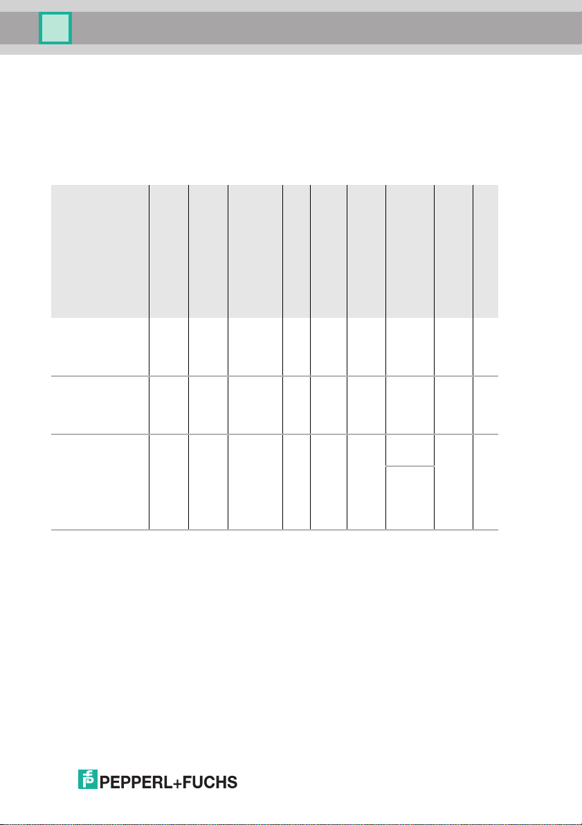
4.1.1 AS-i 3.0 PROFINET Gateway with integr. Safety Monitor
Article No.
VBG-PN-K30-DMD-S16
VBG-PN-K30-D-S16
VBG-PN-K30-DMD-S16EV
1. power supply, 1 gateway for 2 AS-i networks, inexpensive power supplies:
- "yes, max. 4A/AS-i network":
Cost-effective power for 2 AS-i networks with 1 power supply (optionally supply of multiple Single Gateways by 1
power supply).
- "no, max. 8A/AS-i network, redundant supply":
1 power supply per AS-i network. Gateway is powered in normal operation from one of the two AS-i power supplies.
Should one AS-i power supply fail, switching to the other AS-i power supply allows all the diagnostics functions to
be maintained and the unaffected AS-i network continues to operate.
"no, max. 8A/AS-i network":
1 power supply per AS-i network
2. Ethernet fieldbus + RS 232:
Access to AS-i master and safety monitor via Pepperl+Fuchs proprietary software over Ethernet fieldbus interface
or RS 232 interface and adapter cable.
3. AS-i Power24V capable:
- VBG-PN-K30-DMD-S16-EV device can be operated directly on a 24V (PELV) power supply
- with integrated data coupling coils and adjustable self-resetting fuses for safe use also of powerful 24V power supplies.
27.09.2013
Type
Safety,
PROFINET
Safety,
PROFINET
Safety,
PROFINET
Inputs safety, expandable to
max.
62 x
2 channels
max.
62 x
2 channels
max.
62 x 2
channels,
max.
1922
in max.
configuration
Outputs Safety, SIL 3, cat. 4
Safety outputs,
independent according to SIL 3,
Safety communication
Number of AS-i networks,
number of AS-i Master
1 power supply,
4 release
circuits;
2 x relay,
2 x fast
electronic
safe outputs
4 release
circuits;
2 x relay,
2 x fast
electronic
safe outputs
4 release
circuits;
2 x relay,
2 x fast
electronic
safe outputs
Tab. 4-1. Funcion range "AS-i 3.0 PROFINE T Gateway with integr. Safety Monitor"
max.
16
max.
16
max.
32,
max.
992 in
max.
configuration
-
-
Safe
Link
2 AS-i
networks, 2
AS-i
Masters
2 AS-i
networks, 1
AS-i
Master
2 AS-i
networks, 2
AS-i
Masters
1 gateway for 2 AS-i networks1Diagnostic and
no, max.
8A/AS-i
network,
redundant
supply
no, max.
8A/AS-i
network,
redundant
supply
no, max.
4A/AS-i
Kreis
Power24V
Ethernet
fieldbus
+ RS 232
Ethernet
fieldbus
+ RS 232
Ethernet
fieldbus
+ RS 232
3
configuration interface2Programming in C
no
no
optional
11
Page 12
AS-i 3.0 PROFINET Gateway with integr. Safety Monitor
General
The AS-i 3.0 PROFINET Gateway with integr. Safety Monitor combines two devices in one housing: an AS-i/PROFINET Gateway and a Safety Monitor for 2 ASi circuits.
The safety unit provides 4 inputs which can be defined as either EDM or as
START inputs.
AS-i/PROFINET-Gateways serve to connect AS-i systems to the superordinate
PROFINET controller. It acts as a master for AS-i and as a slave on field bus level.
Commissioning, debugging and setting up of the AS-i parameters can be accomplished with the use of the display, but it can also be handled via the diagnostic interface and the field bus.
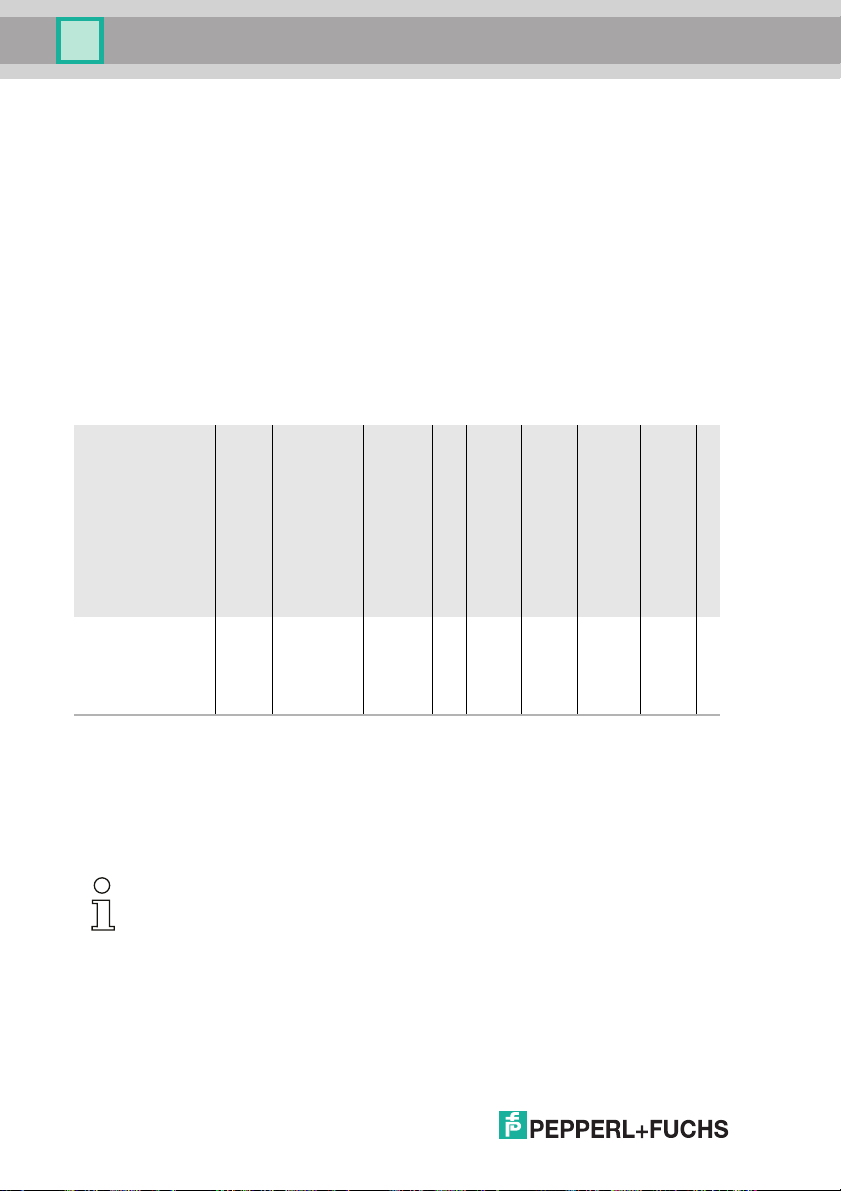
4.1.2 AS-i 3.0 Gateway PROFINET via PROFIsafe
VBG-PNS-K30-DMD
12
Article No.
PROFIsafe,
PROFINET
Type
max.
62 x
2 channels
Inputs safety, expandable to
Outputs Safety, SIL 3, cat. 4
Safety outputs,
independent according to SIL 3,
Safety communication
Number of AS-i networks,
number of AS-i Master
1 power supply,
4 release
circuits;
2 x relay,
2 x fast
electronic
safe outputs
max.
16
Tab. 4-2. Funcion range "AS-i 3.0 Gateway PROF INET via PROFIsafe"
PROFI
safe
(F-CPU)
2 AS-i
networks,
2AS-i
Masters
1 gateway for 2 AS-i networks
no, max.
8A/AS-i
network,
redundant supply
Diagnostic and
configuration interface
RS 232 +
Ethernet
no
The AS-i 3.0 Gateway PROFINET via PROFIsafe is a combination of an AS-i/
PROFINET Gateway with a PROFIsafe F-device. It is used for transmitting of
safety related data to/from SaW slaves via the standard field bus PROFINET.
The gateway supports 64 release circuits. The integrated safety unit provides 4
non-safety inputs. PROFIsafe transfers input status data to F-Host.
Information!
PROFIsafe is a certified acc. to IEC 61508 profile for PROFIBUS and PROFINET. With
SIL 3 (Safety Integrity Level) or category 4 acc. to EN 954-1 fulfills PROFIsafe the
highest safety requirements for the process- and manufacturing industry. Both safety
related and standard communication are possible via one and the same cable.
AS-i/PROFINET-Gateways serve to connect AS-i systems to the superordinate
PROFINET controller. It acts as a master for AS-i and as a slave on field bus level.
Programming in C
27.09.2013
Page 13

AS-i 3.0 PROFINET Gateway with integr. Safety Monitor
General
Commissioning, debugging and setting up of the AS-i parameters can be accomplished with the use of the display, but it can also be handled via the diagnostic interface and the field bus.
4.2 New Generation of AS-i Gateways with ethernet diagnostics interface
The plus points of the new Gateway generation at a glance:
• Gateways now programmable in C
• Ethernet diagnostics interface for remote diagnostics
• Integrated web server: diagnostics for the Gateways and the AS-i circuits
over Ethernet possible with no additional software
• GSD configuration files already stored in the web server
• Earth fault monitor distinguishes between AS-i cable and sensor cable
• Current from both AS-i circuits in the "1 Gateway, 1 power supply for 2 AS-i
circuits" version can now be read directly on the unit
• Self-resetting fuses in the "1 Gateway, 1 power supply for 2 AS-i circuits" version
• Device temperature display
• AS-i Power24V capable
• Interfaces for virtually every bus system and Ethernet solution
Information!
See also section <Functions of the new generation of AS-i Gateways> for further information.
27.09.2013
13
Page 14
AS-i 3.0 PROFINET Gateway with integr. Safety Monitor
General
4.3 Brief description
The actuator-sensor interface (AS-i) has established itself as a system for networking primarily binary sensors and actuators at the lowest level of the automation hierarchy. The high number of installed systems, the ease of use and the reliable operating behaviour also make the AS-i interesting in the area of machine
safety.
The safety AS-i system is intended for safety applications up to Category 4/SIL 3.
Mixed operation of standard components and safe components is possible.
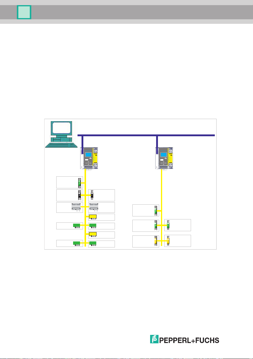
AS-i 3.0 Gateway PROFINET via PROFIsafe
The safety unit monitors within an AS-i system the safe slaves which have been
assigned according to the configuration specified by the user with the configuration software. This safety information is transmitted to PROFIsafe.
SPS
1.13
2.13+24 V
0 V
+
2.Y2
2.Y1
Aux
AS-i Safety
Integrated
1.Y1
1.Y2
2.Y1
2.Y2
K1
K2
K3
K4
1.Y2
1.Y1
+
Mode
2.14
3.14
4.14+1.14
ESC
OK
Service
Set
ASI
+PWR+ASI
+ASI 1
1
2
+ASI
Safety In
Adr. 1
Analog In
Adr. 3
Analog In
Adr. 10
OEM 3O
Adr. 22A
OEM 4I/4O
Adr. 26
Abb. 4-1. Safe and standard components in an AS-i network
Analog In
Adr. 4
Analog In
Adr. 11
OEM Safety
Adr. 21
OEM 3O
Adr. 23A
OEM Safety
Adr. 24
OEM 2I/2O
Adr. 27
Safety In
Adr. 6
Safety In
Adr. 12
Safety Out
Adr. 4/7B
2.13+24 V
0 V+1.13
2.Y2
2.Y1
Aux
AS-i Safety
Integrated
1.Y1
1.Y2
2.Y1
2.Y2
K1
K2
K3
K4
1.Y2
1.Y1
Mode
2.14+4.14+1.14
3.14
ESC
OK
Service
Set
ASI
+PWR+ASI
+ASI 1
1
2
+ASI
Safety In
Adr. 13
Safety Out
Adr. 2/7A
14
27.09.2013
Page 15
AS-i 3.0 PROFINET Gateway with integr. Safety Monitor
General
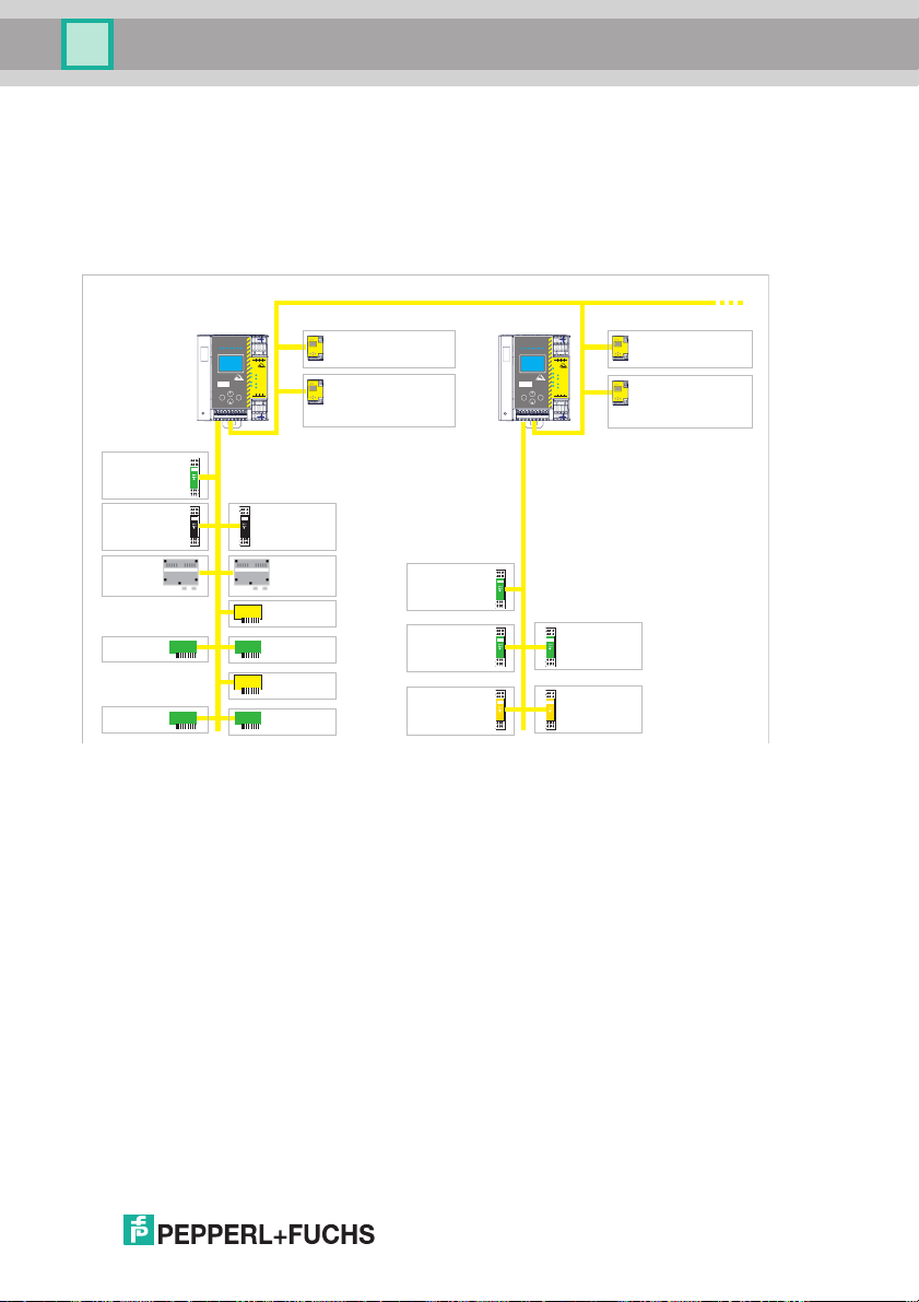
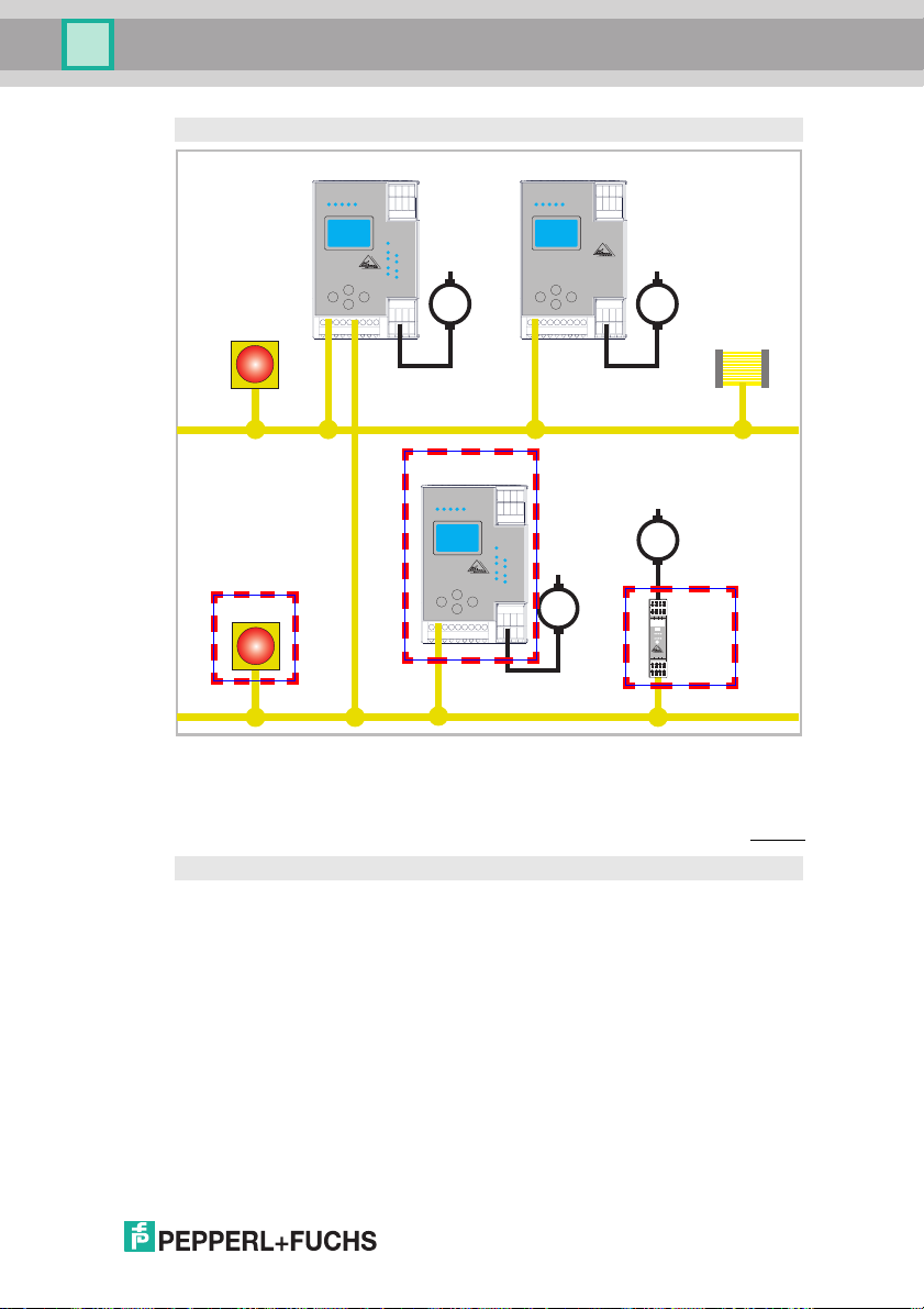
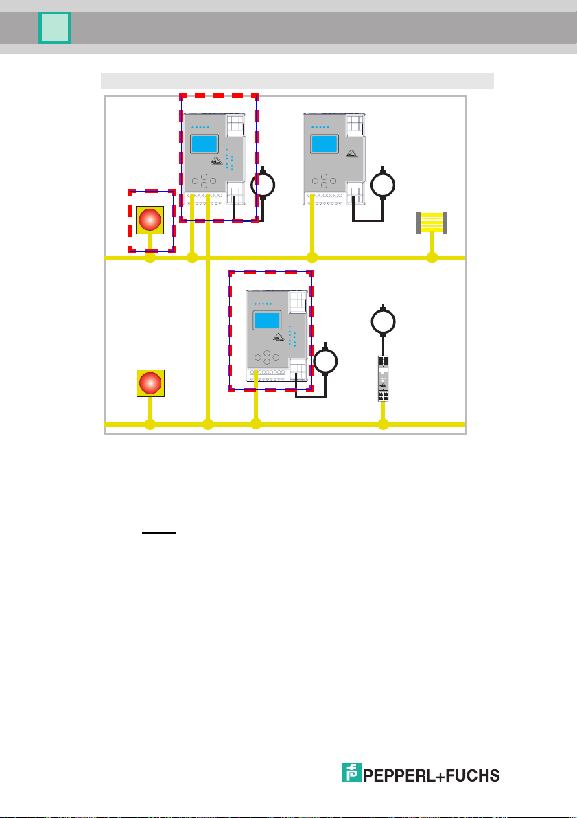
AS-i 3.0 PROFINET Gateway with integr. Safety Monitor
The AS-i/PROFINET Gateway monitors within an AS-i system the safe slaves
which have been assigned according to the configuration specified by the user
with the configuration software. In the event of a stop request or a defect, the ASi/PROFINET Gateway switches off the system in protective operation mode with a
maximum reaction time of 40 ms.
AS-i coupling circuit
Analog In
Adr. 10
OEM 3O
Adr. 22A
OEM 4I/4O
Adr. 26
Safety In
Adr. 1
Analog In
Adr. 3
coupling slave Adr. 1
Analog In
Adr. 11
OEM Safety
Adr. 21
OEM 3O
Adr. 23A
OEM Safety
Adr. 24
OEM 2I/2O
Adr. 27
lightgrids 1
coupling slave Adr. 2
emergency-stop
circuit 1
Safety In
Adr. 6
Safety In
Adr. 12
Safety Out
Adr. 4/7B
1.13
2.13+24 V
0 V
+
2.Y2
2.Y1
Aux
AS-i Safety
Integrated
1.Y1
1.Y2
2.Y1
2.Y2
K1
K2
K3
K4
1.Y2
1.Y1
+
Mode
2.14
3.14
4.14+1.14
ESC
OK
Service
Set
Safety In
Adr. 13
Safety Out
Adr. 2/7A
1.13
2.13+24 V
0 V
+
2.Y2
2.Y1
Aux
AS-i Safety
Integrated
1.Y1
1.Y2
2.Y1
2.Y2
K1
K2
K3
K4
1.Y2
1.Y1
+
Mode
2.14
3.14
4.14+1.14
ESC
OK
Service
Set
Analog In
Adr. 4
coupling slave Adr. 6
silent running
coupling slave Adr. 7
emergency-stop
circuit 2
Abb. 4-2. Safe and standard components in an AS-i network
Multiple AS-i Safety Monitors can be used within an AS-i system. In this way, a
safe slave can be monitored by multiple AS-i Safety Monitors.
27.09.2013
15
Page 16

AS-i 3.0 PROFINET Gateway with integr. Safety Monitor
Specifications - AS-i/PROFINET Gateways
5. Specifications - AS-i/PROFINET Gateways
5.1 Technical data
The technical data are placed in the data sheet. Please view the current version
on the web page: http://www.pepperl-fuchs.com.
Attention!
The AS-I power supply for the AS-I components must have isolation per IEC 60 742
and be able to handle momentary power interruptions of up to 20 ms. The power supply for the 24 V supply must also have isolation per IEC 60 742 and be able to handle
momentary power interruptions of up to 20 ms. The maximum output voltage of the
power supply must also be less than 42 V in case of a fault.
16
27.9.2013
Page 17
AS-i 3.0 PROFINET Gateway with integr. Safety Monitor
Specifications - AS-i/PROFINET Gateways
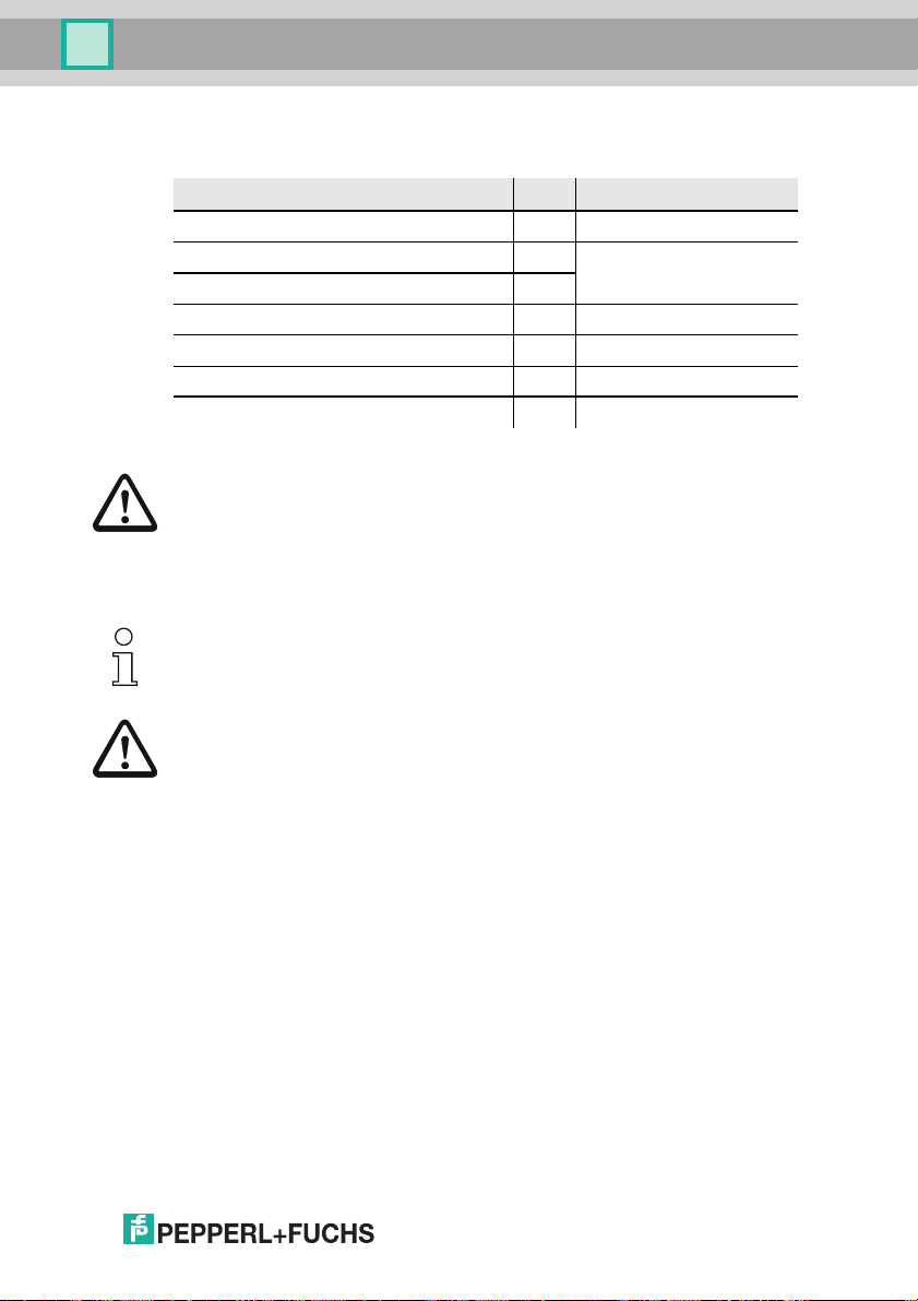
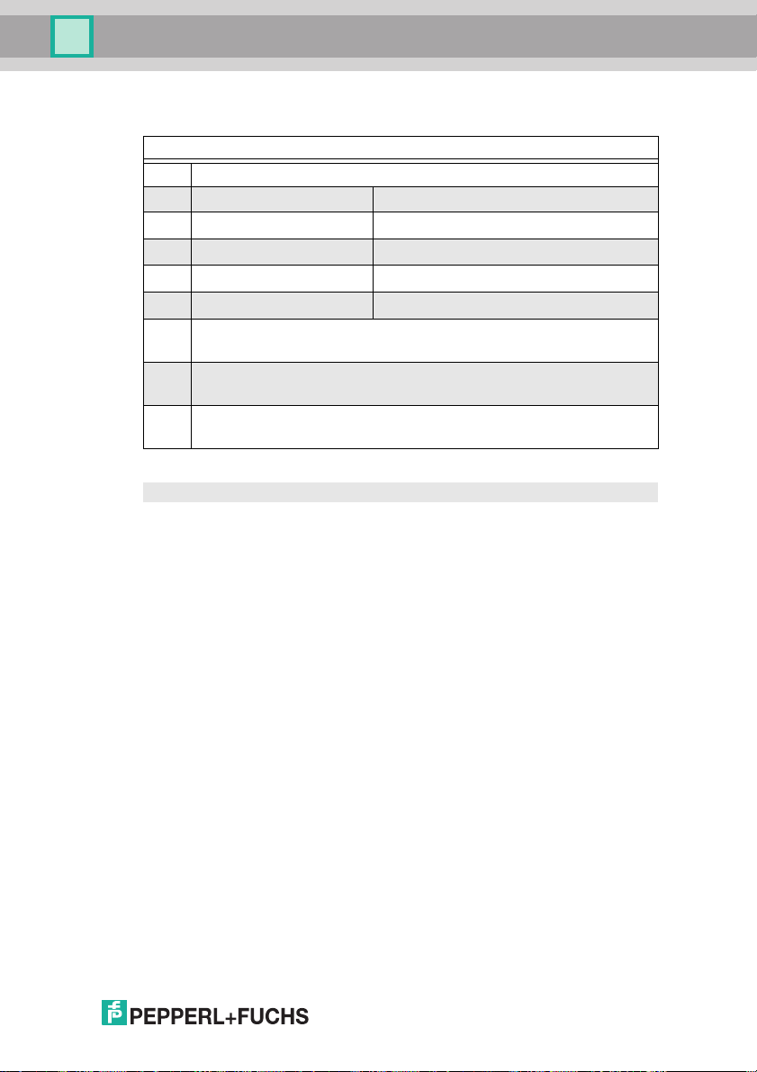
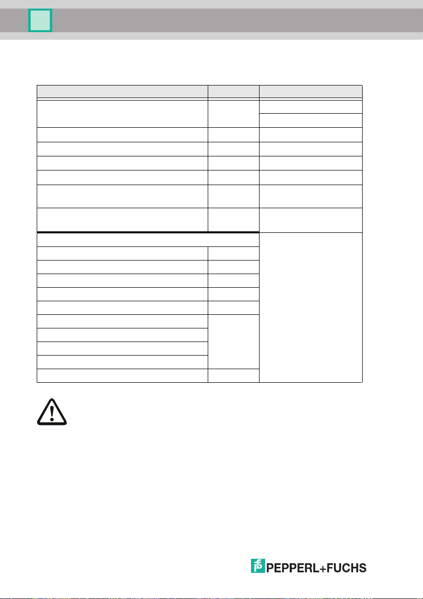
5.2 Safety-relevant characteristic data
Characteristic data Value Standard
Safety category 4 EN 954-1
Safety category 4 EN ISO 13849-1: 2008
Performance Level (PL) e
Safety Integrity Level (SIL) 3 EN 61508: 2001
Lifespan (TM) in years 20 EN ISO 13849-1: 2008
Maximum switch-on time in months 12 EN 61508: 2001
Max. system reaction time in milliseconds
Attention!
In addition to the system reaction time of max. 40 ms, the reaction times of the safe ASinterface sensor slave, of the sensor being used for monitoring, of the safe AS-interface
actuator slave and of the actuator used for this purpose must still be added. Please note
that additional reaction times may likewise arise through the configuration of the safety
monitor.
Notice!
Refer to the technical data for the slaves as well as to that for the sensors and actuators
for the reaction times to be added.
40 EN 61508: 2001
Tab. 5-3.
Attention!
The system reaction times of the daisy-chained AS-interface components are added up.
27.9.2013
17
Page 18
AS-i 3.0 PROFINET Gateway with integr. Safety Monitor
Specifications - AS-i/PROFINET Gateways
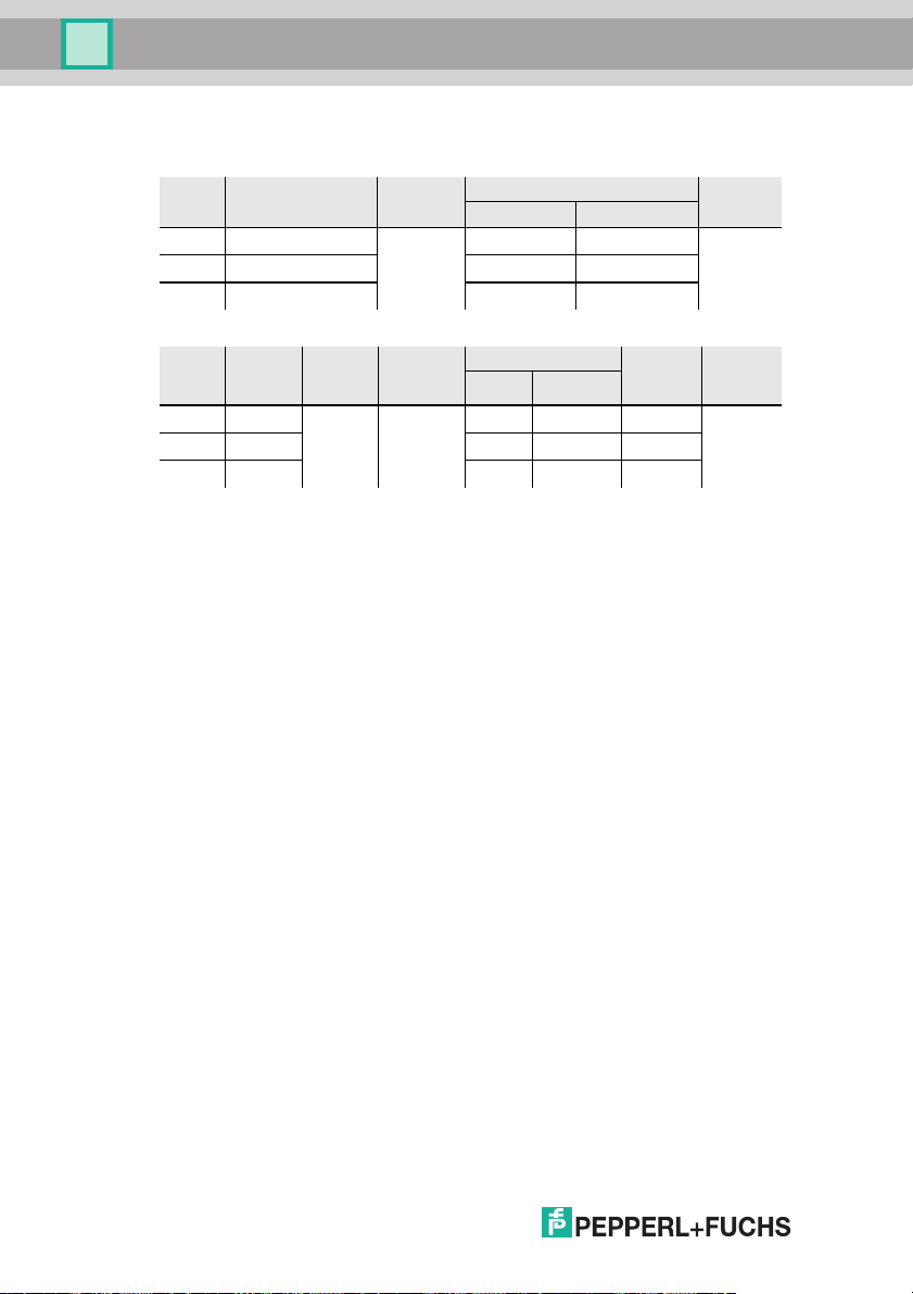
5.2.1 Overview of parameter for determining the failure rates
nop/y switching intervals
t
[s]
cycle
B10d
value
electromechanics Standard
MTTFd [years] PFH [1/h]
105.120 300 2.500.000 237,82
52.560 600 475,65
8.760 3600 2853,88
nop/y switching
intervals
t
cycle
105.120 300 2.500.000
B10d
value
electronics
PFH
-09
4,76 E
electromechanics PFH
MTTFdPFH
237,82
52.560 600 475,65
8.760 3600 2853,88
-9
9,908 x 10
-9
4,853 x 10
-10
9,054 x 10
total
1,12 x 10-81,6 x 10
5,09 x 10-99,85 x 10
-10
7,82 x 10
5,54 x 10
-8
-9
-9
EN ISO
13849-1
Tab. 5-4.
Standard
EN 62061
EN 61508
Tab. 5-5.
18
27.9.2013
Page 19
AS-i 3.0 PROFINET Gateway with integr. Safety Monitor
Specifications - AS-i/PROFINET Gateways
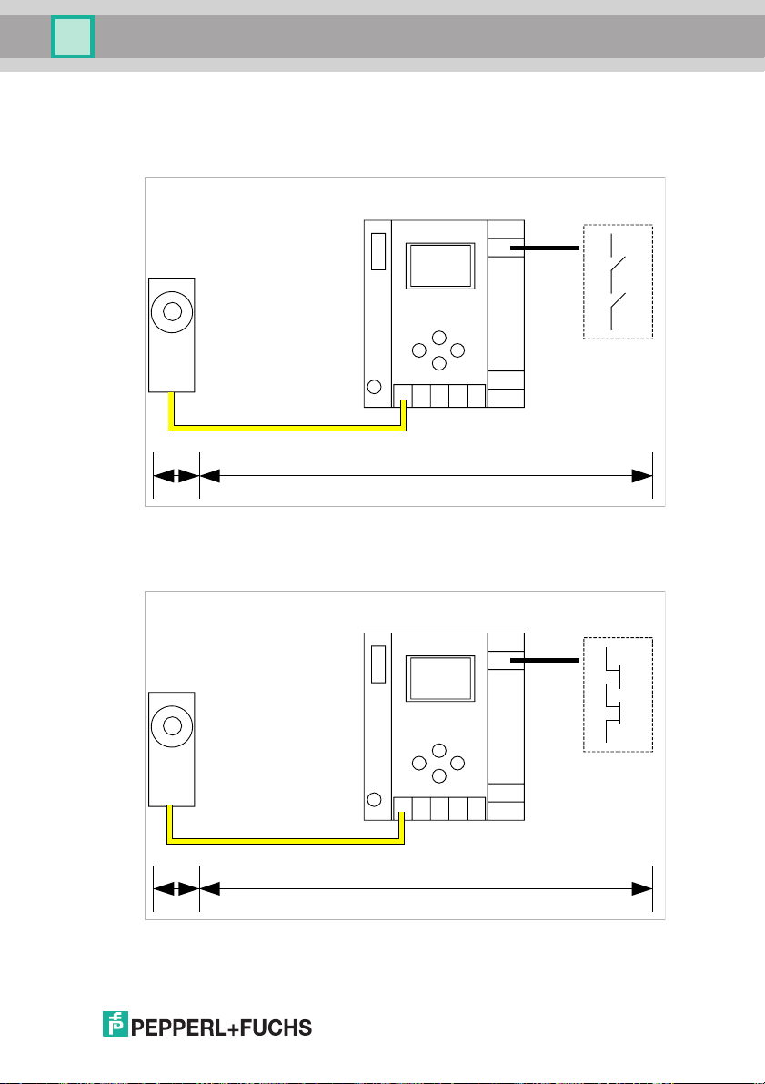
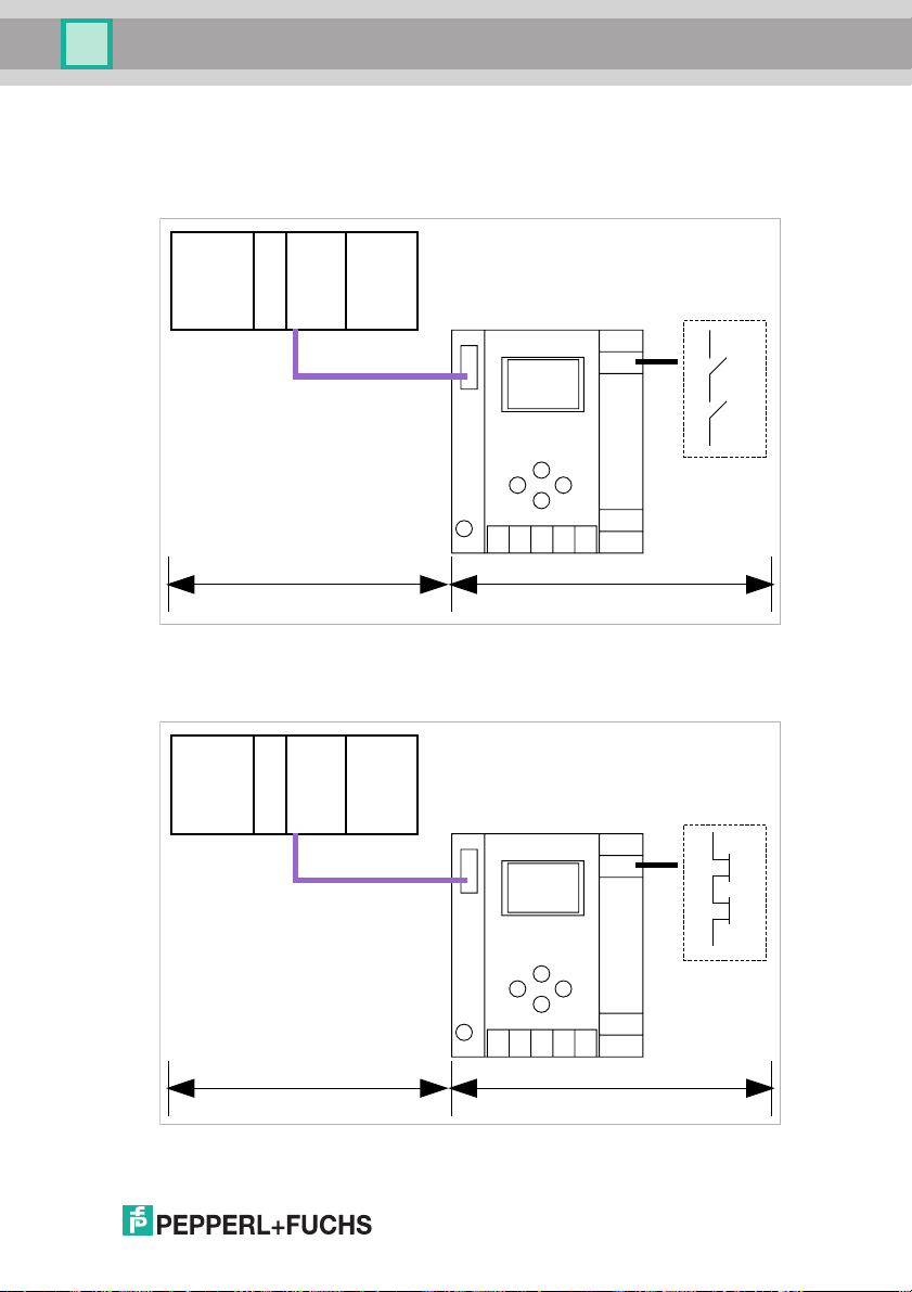
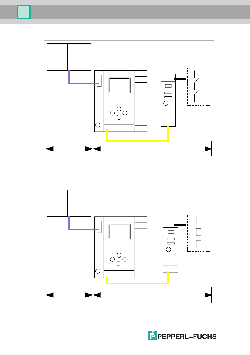
5.3 Reaction times
5.3.1 Sensor -> local relay output
Sensor
t
t
s
ts = maximal reaction time of the sensor (see data sheet)
t
= maximal system reaction time
react
react
= 40ms
1.13
2.13
1.14
2.14
5.3.2 Sensor -> local electronic output
Sensor
t
s
ts = maximal reaction time of the sensor (see data sheet)
t
= maximal system reaction time
react
27.9.2013
t
react
24V
3.14
4.14
= 30ms
19
Page 20
AS-i 3.0 PROFINET Gateway with integr. Safety Monitor
Specifications - AS-i/PROFINET Gateways
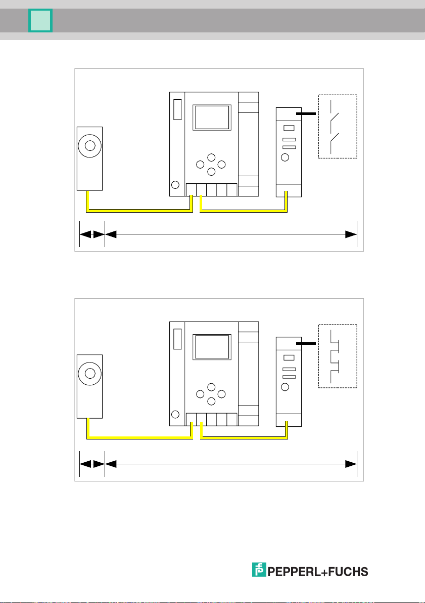
5.3.3 Sensor -> AS-i relay output
1.13
1.14
1.23
1.24
Sensor
t
s
ts = maximal reaction time of the sensor (see data sheet)
t
= maximal system reaction time
react
5.3.4 Sensor -> AS-i electronic output
Sensor
t
s
ts = maximal reaction time of the sensor (see data sheet)
t
= maximal system reaction time
react
t
react
t
react
Relay output
= 85ms
24V
1.14
2.14
Electronic output
= 85ms
20
27.9.2013
Page 21
AS-i 3.0 PROFINET Gateway with integr. Safety Monitor
Specifications - AS-i/PROFINET Gateways
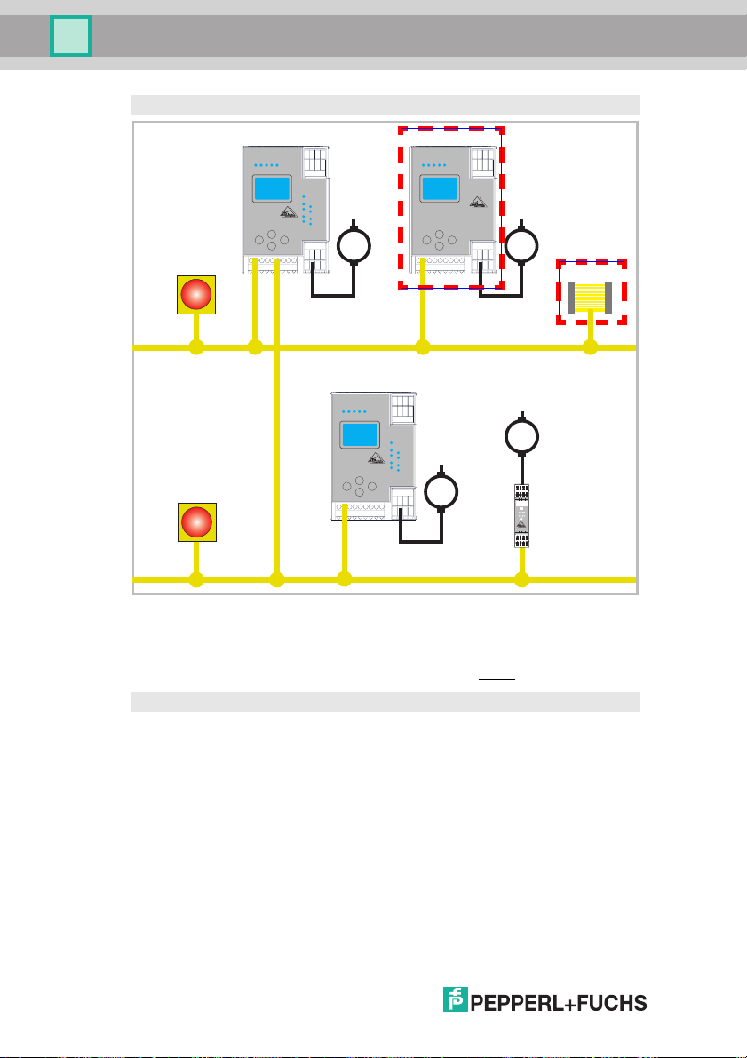
5.3.5 System reaction times – example calculations
System components:
AS-i network 1
ASI1
AS-i network 2
ASI2
Safe sensor slave (EMERGENCY-OFF switch: t
S1-1
Safe sensor slave (safety light barrier: t
S1-2
Safe sensor slave (EMERGENCY-OFF switch: t
S2-1
Safe actuator slave (motor starter: t
A2-1
SM1-1 Safety monitor with 16 relais circuits and one safe AS-i output in AS-i
network 1
SM1-2 Safety monitor with 2 relais circuits and one safe AS-i output in AS-i
network 1
SM2-1
Safety monitor with 16 relais circuits and one safe AS-i output in AS-i
network 2
System configuration - example 1: Calculation of the system reaction time
RA2-1
= 18 ms)
RS1-2
= 50ms)
RS1-1
RS2-1
= 100 ms)
= 100ms)
Tab. 5-6.
27.9.2013
21
Page 22
AS-i 3.0 PROFINET Gateway with integr. Safety Monitor
Specifications - AS-i/PROFINET Gateways
System configuration - example 1: Calculation of the system reaction time
SM1-1
AS-i Safety Monitor
M
S1-1
SM1-2
AS-i Safety Monitor
M
S1-2
AS-i 1
SM2-1
M
AS-i Safety Monitor
S2-1
M
AS-i 2
Upon activation of safety light barrier S1-2, the relay safety output of safety monitor SM1-2 is controlled.
Calculation of the AS-i relevant system reaction time:
t
System total a)
= t
R S1-2
+ t
= 18ms + 40ms = 58ms
R System
System configuration - example 2: Calculation of the system reaction time
I–
I+
I1
I2
Run
1
I
Pwr
Prg
1.13
1.14
ASI+
ASI–
I+
I+
1.Y1
1.Y2
Prg
I2
1.Y2
1.Y1
Alarm
Fault
Out
1.23
1.24
nc
nc
A2-1
22
27.9.2013
Page 23
AS-i 3.0 PROFINET Gateway with integr. Safety Monitor
Specifications - AS-i/PROFINET Gateways
System configuration - example 2: Calculation of the system reaction time
SM1-1
AS-i Safety Monitor
M
S1-1
SM1-2
AS-i Safety Monitor
M
S1-2
AS-i 1
SM2-1
M
AS-i Safety Monitor
S2-1
M
AS-i 2
Upon locking of the EMERGENCY-OFF switch S2-1, the motor starter is controlled via the safe AS-interface output of safety monitor SM2-1.
Calculation of the AS-interface-relevant system reaction time:
t
System total b)
= t
R S2-1
+ t
R System
+ t
= 100ms + 40ms + 50ms = 190ms
R A2-1
System configuration - example 3: Calculation of the system reaction time
I–
I1
Run
Prg
1.13
ASI+
I+
I+
I+
I2
1.Y1
1.Y2
Prg
1
I
I2
1.Y2
1.Y1
Alarm
Pwr
Fault
Out
1.14
1.23
1.24
ASI–
nc
nc
A2-1
27.9.2013
23
Page 24
AS-i 3.0 PROFINET Gateway with integr. Safety Monitor
Specifications - AS-i/PROFINET Gateways
System configuration - example 3: Calculation of the system reaction time
SM1-1
AS-i Safety Monitor
M
S1-1
SM1-2
AS-i Safety Monitor
M
S1-2
AS-i 1
SM2-1
M
AS-i Safety Monitor
S2-1
M
AS-i 2
Upon locking of the EMERGENCY-OFF switch S1-1, the relay output of safety
monitor SM2-1 is controlled via the coupling of the safe AS-interface output of
safety monitor SM1-1.
Calculation of the AS-i relevant system reaction time:
t
System total c)
= t
R S1-1
+ t
R System ASI1
+ t
R System ASI2
40ms = 180ms
I+
I+
I+
I–
1.Y2
1.Y1
I2
I1
A2-1
Run
Prg
1
I
I2
1.Y2
1.Y1
Alarm
Pwr
Fault
Out
Prg
1.24
1.23
1.14
1.13
nc
nc
ASI–
ASI+
= 100ms + 40ms +
5.4 Scope of delivery
The basic unit consists of:
AS-i 3.0 PROFINET Gateway with integr. Safety Monitor.
The following accessories are available:
Software CD with
• ASIMON 3 G2 communication software for Microsoft
Windows 7/Windows 8
• System manual in PDF format (Adobe® Reader® Version 7.x or newer is
required for viewing the files)
24
®
Windows XP/Vista/
®
27.9.2013
Page 25

AS-i 3.0 PROFINET Gateway with integr. Safety Monitor
Specifications - AS-i/PROFIsafe Gateway
6. Specifications - AS-i/PROFIsafe Gateway
6.1 Technical data
The technical data are placed in the data sheet. Please view the current version
on the web page: http://www.pepperl-fuchs.com.
Attention!
The AS-I power supply for the AS-I components must have isolation per IEC 60 742
and be able to handle momentary power interruptions of up to 20 ms. The power supply for the 24 V supply must also have isolation per IEC 60 742 and be able to handle
momentary power interruptions of up to 20 ms. The maximum output voltage of the
power supply must also be less than 42 V in case of a fault.
27.9.2013
25
Page 26
AS-i 3.0 PROFINET Gateway with integr. Safety Monitor
Specifications - AS-i/PROFIsafe Gateway
6.2 Safety-relevant characteristic data
Characteristic data Value Standard
Safety category 4 EN 954-1
EN ISO 13849-1: 2008
Performance Level (PL) e EN ISO 13849-1: 2008
Safety Integrity Level (SIL) 3 IEC 61508: 2001
Lifespan (TM) in years 20 EN ISO 13849-1: 2008
Maximum switch-on time in months 12 IEC 61508: 2001
PFD
PFH
D
(probability of a dangerous failure per hour)
Max. system reaction time in milliseconds
PROFIsafe → local relay output 15
PROFIsafe → local electronic output 5
PROFIsafe → AS-i relay output 60
PROFIsafe → AS-i electronic output 50
AS-i → PROFIsafe 30
PROFINET → local output 40
PROFINET → AS-i
AS-i → local output
AS-i → AS-i
AS-i → PROFINET 50
Attention!
In addition to the system reaction time in the gateway, eventually reaction times of
other daisy-chained safe AS-i and PROFIsafe componentshave to be added too.
Please note that additional reaction times may likewise arise through the configuration
of the safety unit.
< 9,25 x 10
< 5,36 x 10
-6
IEC 61508: 2001,
EN 62061: 2005
-9
IEC 61508: 2001,
EN 62061: 2005
IEC 61508: 2001
Tab. 6-7.
26
27.9.2013
Page 27
AS-i 3.0 PROFINET Gateway with integr. Safety Monitor
Specifications - AS-i/PROFIsafe Gateway
6.3 Reaction times
6.3.1 Ethernet (PROFIsafe) -> local relay output
1.13
2.13
1.14
2.14
t
ethernet
t
= reaction time PROFIsafe type 150ms
ethernet
t
= maximal system reaction time
react
6.3.2 Ethernet (PROFIsafe) -> local electronic output
t
ethernet
t
= reaction time PROFIsafe type 150ms
ethernet
t
= maximal system reaction time
27.9.2013
react
t
= 15ms
react
24V
1.14
2.14
t
= 5ms
react
27
Page 28
AS-i 3.0 PROFINET Gateway with integr. Safety Monitor
Specifications - AS-i/PROFIsafe Gateway
6.3.3 Ethernet (PROFIsafe) -> AS-i relay output
1.13
1.14
1.23
1.24
Relay output
t
ethernet
t
= reaction time PROFIsafe type 150ms
ethernet
t
= maximal system reaction time
react
6.3.4 Ethernet (PROFIsafe) -> AS-i electronic output
t
react
t
ethernet
t
= reaction time PROFIsafe type 150ms
ethernet
t
= maximal system reaction time
react
t
react
= 60ms
24V
1.14
2.14
Electronic output
= 50ms
27.9.2013
28
Page 29
AS-i 3.0 PROFINET Gateway with integr. Safety Monitor
Installation
7. Installation
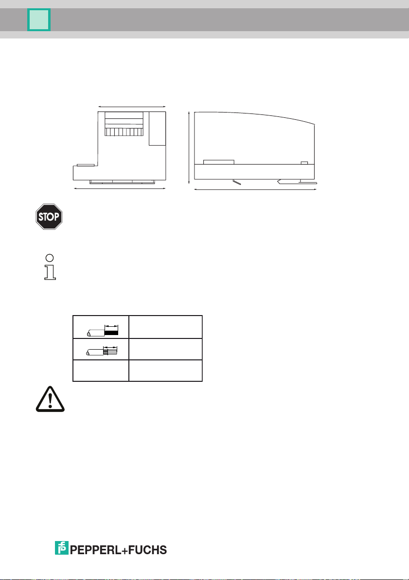
7.1 Dimensions
80
96
Warning!
Cover the top of the gateway when doing any drilling work above the unit. No particles,
especially metal chips, should be allowed to enter the housing, since this could cause a
short circuit.
Information!
Please refer to installation instruction for this device for detailed mounting information.
7.2 Connections
10
10
AWG 24 ... 12
Attention!
The power supply for the AS-I components must have isolation per IEC 60 742 and be
able to handle momentary power interruptions of up to 20 ms. The power supply for
the 24 V supply must also have isolation per IEC 60 742 and be able to handle
momentary power interruptions of up to 20 ms. The maximum output voltage of the
power supply must also be less than 42 V in case of a fault.
110
0,2 ... 2,5 mm
0,2 ... 2,5 mm
120
2
2
27.9.2013
29
Page 30
AS-i 3.0 PROFINET Gateway with integr. Safety Monitor
Installation
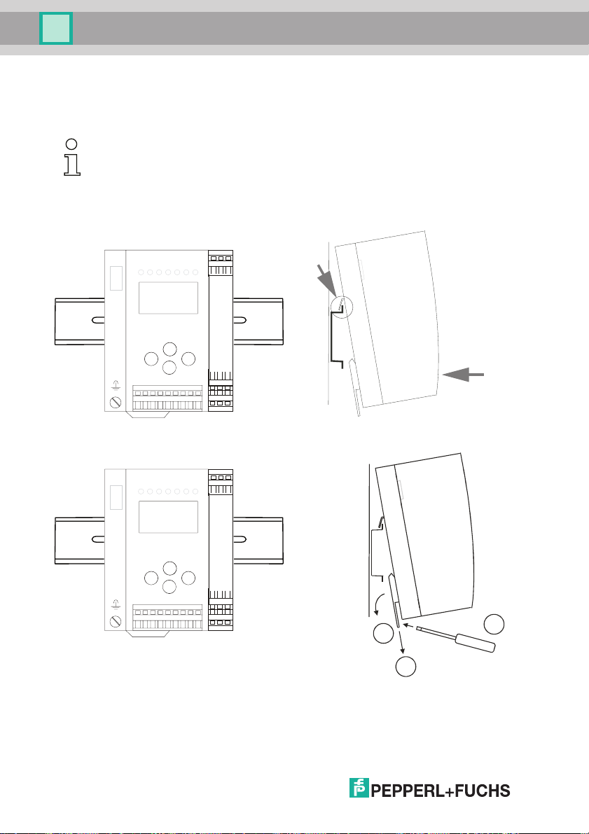
7.3 Installing in the control cabinet
The AS-I/Gateway is installed in the control cabinet on 35mm DIN rails per DIN
EN 50 022.
Information!
The enclosure of the AS-I/Gateway is made of stainless steel. The unit is also suitable for exposed wall mounting.
To install, place the unit on the upper edge of the DIN rail and then snap in the
lower edge.
[1]
-
-
+-+
+
[2]
7.4 Removing
To remove, press the holding clamps [2] down using a screwdriver [1], press the
unit firmly against the upper rail guide and lift out.
30
-
-
+-+
+
3
1
2
27.9.2013
Page 31

AS-i 3.0 PROFINET Gateway with integr. Safety Monitor
Installation
7.5 Commissioning
7.5.1
classical display
Switching to advanced display mode
advanced display mode
OK
LCD
1.12A
UNKNOWN SLAVE
ESC/Service
7.5.2 Setting the PROFINET properties
PROFINET
QUICK SETUP
AS-I SAFETY
DIAGNOSIS
LCD
(OK
(OK oder/or/ou/o/o
PROFINET
TCP/IP
ETHERNET
TCP/IP
ACTUAL VALUES
CONFIGURATION
Restart the Gateway for changes to become effective
LCD
menu structure see additional page
CONFIGURATION
STATIC
IP ADDRESS
192.168.42.53
NETMASK
255.255.255.0
GATEWAY
192.168.42.53
CONFIGURATION
PROFINET ONLY
27.9.2013
31
Page 32

AS-i 3.0 PROFINET Gateway with integr. Safety Monitor
Installation
(OK
(OK
(OK
PROFINET
TCP/IP
ETHERNET
ETHERNET:
PORT 1 MODE:
100BASE-TX FDX
PORT 2 MODE:
NO CONNECTION
MAC ID DEVICE:
00-16-77-10 AF-8C
MAC ID PORT 1:
00-16-77-10 AF-8D
MAC ID PORT 2:
00-16-77-10 AF-8E
PROFINET
TCP/IP
ETHERNET
PROFINET
QUICK SETUP
DIAGNOSIS
SLAVE ADDR TOOL
oder/or/ou/o/o
OK
ESC
100BASE-TX FDX
100BASE-TX HDX
10BASE-T FDX
10BASE-T HDX
NO CONNECTION
TCP/IP
ACTUAL VALUES
CONFIGURATION
ACTUAL VALUES:
IP ADDRESS
192.168.42.53
NETMASK
255.255.255.0
GATEWAY
192.168.42.53
SOURCE
STATIC CONFIG
7.5.3 Setting the PROFIsafe address
Information!
Available only with AS-i PROFIsafe Gateways.
32
27.9.2013
Page 33

AS-i 3.0 PROFINET Gateway with integr. Safety Monitor
Installation
PROFINET
QUICK SETUP
SAFETY
...
↓
PROFINET
QUICK SETUP
SAFETY
...
OK
↓
ASI SAFETY
SAFE OUTPUT CH
PROFISAFE
START/STOP
...
7.5.4 Connecting AS-i Slaves
AS-i
Power
PROFINET
Config error
U AS-i
AS-i active
prg enable
prj mode
AS-i Master
AS-i
Power
PROFINET
Config error
U AS-i
AS-i active
prg enable
prj mode
PROFISAFE ADDR.
Status
OK
PROFISAFE ADDR.
06
↓
OK
↓
PROFISAFE ADDR.
17
LCD
1. 1
AS-i Master
0.5s
AS-i
AS-i
Slave 1
AS-i
Slave 5
27.9.2013
1. 41
SEARCHING SLAVES
LCD
Slave 1
AS-i
Slave 5
1. 5
0.5s
33
Page 34

AS-i 3.0 PROFINET Gateway with integr. Safety Monitor
Installation
7.5.5 Quick setup
config error
OK
1. 5
1xOK
PROFINET
QUICK SETUP
ASI SAFETY
DIAGNOSIS
OK
WARNING:
OUTPUTS MAY BE
RESET
OK
LCD
STORE AS-I
CONFIGURATION
OK
STORE +PRJ MODE
↓
config error
LCD
CONFIGURATION OK
10s
Host error
no connection
1: ON 2: OFF
LCD
LCD
LCD
LCD
↓
STORE AS-I
CONFIGURATION
STORE +RUN
STORE +PRJ MODE
34
LCD
27.9.2013
Page 35

AS-i 3.0 PROFINET Gateway with integr. Safety Monitor
Installation
7.5.6 Error tracing
7.5.6.1 Faulty slaves
Power
PROFINET
Config error
U AS-i
AS-i
AS-i active
prg enable
prj mode
AS-i Master
1.1
MISSING SLAVE
LCD
AS-i
Slave 1
AS-i
Slave 5
AS-i
Slave 24
7.5.6.2 Error display (last error)
Power
PROFINET
Config error
U AS-i
AS-i active
prg enable
prj mode
AS-i
AS-i
Slave 1
AS-i
Slave 5
AS-i
Slave 24
AS-i Master
Power
PROFINET
Config error
U AS-i
AS-i active
prg enable
prj mode
AS-Interface
AS-i
Slave 1
AS-i
Slave 5
AS-i
Slave 24
2s
1.24
MISSING SLAVE
2s
AS-i Master
set/↓
LCD
LCD
PROFINET error
No connection
1: ON 2: OFF
24
27.9.2013
35
Page 36

AS-i 3.0 PROFINET Gateway with integr. Safety Monitor
Installation
7.6 Addressing
7.6.1 Assigning address 15 to slave currently at address 2
1. 41
SEARCHING SLAVE
OK
↓
LCD
4x
OK
SLAVE ADR TOOL
OLD ADDRESS 2
NEW ADDRESS 0
PRG
6x
OK
1x
↓
QUICK SETUP
AS-I SAFETY
DIAGNOSIS
SLAVE ADDR TOOL
OK
AS-I CIRCUIT 1
AS-I CIRCUIT 2
OK
SLAVE ADR TOOL
CONNECT NEW SLAVE
OLD ADDRESS
NEW ADDRESS
OK
Master Slave
Connect module
Hinweis!
Weitere Informationen finden Sie im Kap. <Bedienung im erweiterten Anzeigemodus>.
2 x ESC
SLAVE ADR TOOL
OLD ADDRESS 2
NEW ADDRESS 15
PRG
↓
SLAVE ADR TOOL
OLD ADDRESS 2
NEW ADDRESS 15
PRG
OK
SLAVE ADR TOOL
CONNECT NEW SLAVE
OLD ADDRESS
NEW ADDRESS
1. 15
UNKNOWN SLAVE
36
27.9.2013
Page 37

AS-i 3.0 PROFINET Gateway with integr. Safety Monitor
Installation
7.7 Local parameter setting of safe AS-i Gateways and Monitors
CHIPCARD AND
DATA
DIFFERENT
CARD->MASTER
MASTER->CARD
CONTINUE
Daten kopieren
Keine Aktion erforderlich
CHIPCARD FOUND
DATA WILL
BE SYNCHRONIZED
Keine Aktion erforderlich
Master->Karte
Karte->Master oder
/No action required/
/Aucune action requise/
/No action required/
/Aucune action requise/
Unsichere Daten / Non-safe data/
Données non-sécurisées/
Dati non sicuri / Datos no seguros/
Geräte+Chipdaten ungleich
(Werkskonfiguration geändert)
/Device+card data not equal
(Factory configuartion changed)
Fehlermeldung:
/Error message/
Geräte+Chipdaten gleich
/Device data+card data equal/
Keine Meldung
Karte leer + formatiert
/Card empty + formatted/
Daten werden synchronisiert:
/No message/
/Data being synchronized/
/Copy data Card->Master
or Master->Card/
/Copier données Carte->Maître ou
Maître-Carte/
/Copiare dati Chipcard->Master o
copiare dati Master->Chipcard/
/Copiar datos TarjetaChip->Maestro
o Maestro ->TarjetaChip/
/Nessuna azione richiesta/
/Ninguna acción requrida/
/Nessuna azione richiesta/
/Ninguna acción requrida/
konfiguration)
en kompatibel
(Werks
Dat
/Data compatible (factory
Daten nicht kompatibel
/Data not compatible/
/
Card not formatted
Karte nicht formatiert
/
27.9.2013
DATA FROM
Daten werden übernommen:
/Data being acepted/
configuration)/
CHIPCARD NOT
COMPATIBLE
Fehlermeldung:
/Error message/
NEW CHIPCARD
WILL BE FORMATTED
Karte wird formatiert:
/Formatting card /
CHIPCARD TAKEN
DATA WILL BE
SYNCHRONIZED
Keine Aktion erforderlich
/No action required/
/Aucune action requise/
/Nessuna azione richiesta/
/Ninguna acción requrida/
Karte löschen
/Clear the card/
/Supprimer carte/
/Cancellare chipcard/
/Borrar tarjeta chip/
Keine Aktion erforderlich
/No action required/
/Aucune action requise/
/Nessuna azione richiesta/
/Ninguna acción requrida/
37
Page 38

AS-i 3.0 PROFINET Gateway with integr. Safety Monitor
Installation
ERROR.
CHIPCARD AND
SAFETY DATA
DIFFERENT.
DELETE CHIPCARD
Stamm-/Vollständige
Konfiguartion auf der Chipkarte
enthalten
/Master configuration or
complete configuration on the
card
Sichere Daten / Safe data/
Données sécurisées/
Dati sicuri / Datos seguros
Stamm-/Vollständige
Konfiguartion auf der Chipkarte
/Master configuration or
complete configuration on the
Gerät enthält keine validierte
Konfiguration
/No validated configuration in
Gerät enthält validierte
Konfiguration, Daten ungleich
/There is a validated
configuration on the card, data
not equal
card
Gerät enthält validierte
Konfiguration
/There is a validated
configuration on the card
the device/
Stamm-/Vollständige
Konfiguartion auf der Chipkarte
/Master configuration or
complete configuration on the
card
Beide Konfigurationen ungleich/
Both configurations not equal
Fehlermeldung:
/Error message/
Beide Konfigurationen gleich/
Both configurations identical
Keine Meldung
/No message/
COPY BANK A TO
Datenfreigabe per
MONITOR
Release-Code notwendig:
/Data release via release code
required/
OR SAFETY DATA
...
RELEASE CODE:
1BDF
---------------
TYPE CODE
1BDF OK
Daten löschen
/Clear data/
/Supprimer données /
/Cancellare dati
Keine Aktion erforderlich
/No action required/
/Aucune action requise/
/Nessuna azione richiesta/
Konfiguration per
Release-Code freigeben
/Validate the configuration
via release code/
/Borrar datos
/Ninguna acción requrida/
/Respecter les indications
de sécurité exposées
dans le manuel ASIMON
/Osservare le istruzioni di
sicurezza riportate nel
manuale ASIMON
/Habilitar la configuración
vía código de liberación/
38
CHIPCARD FOUND
SAFETY DATA WILL
Validierte Konfiguration im
Gerät, Chipkarte leer
/Validated configuration
in the device, chip card empty/
Keine validierte Konfiguration im
Gerät + Chipkarte
/No validated configuration in
the device + chip card/
Sichere Daten auf der
Chipkarte nicht kompatibel
zum Gerät
/Safe data on the chip card
not compatible to the device/
BE SYNCHRONIZED
Daten werden synchronisiert:
/Data being synchronized/
CHIPCARD FOUND
SAFETY DATA WILL
BE SYNCHRONIZED
Daten werden synchronisiert:
/Data being synchronized/
CHIPCARD NOT
COMPATIBLE
Fehlermeldung:
/Error message/
For further information see manual, section <Chip card>
Keine Aktion erforderlich
/No action required/
/Aucune action requise/
/Nessuna azione richiesta/
/Ninguna acción requrida/
Keine Aktion erforderlich
/No action required/
/Aucune action requise/
/Nessuna azione richiesta/
/Ninguna acción requrida/
Karte löschen
/Clear the card/
/Supprimer carte/
/Cancellare chipcard/
/Borrar chip/
27.9.2013
Page 39

AS-i 3.0 PROFINET Gateway with integr. Safety Monitor
Installation
7.8 Replacing a defective safety-related AS-i slave
The new slave must be able to send code sequences and must have the same
address as the old one. The addressing of the new slave is carried out automatically
by default for all Pepperl+Fuchs AS-i Masters. Only one missing slave is allowed!
[2]
ESC/Service
(3 seconds)
[1]
27.9.2013
CONNECT
NEW SLAVE 17
THEN PRESS
SERVICE
[4]
ESC/Service
(3 seconds)
[3]
39
Page 40

AS-i 3.0 PROFINET Gateway with integr. Safety Monitor
Installation
7.9 Replacing the chip card
Always turn off power before inserting or removing the card!
[1]
[2]
old
[3]
7.10 Replacing a defective device
If Safe Link is used, it is necessary to teach the group manager after replacing a
defective device (see next section)!
40
new
27.9.2013
Page 41

AS-i 3.0 PROFINET Gateway with integr. Safety Monitor
Installation
[1]
[2]
old
new
[3]
27.9.2013
41
Page 42

AS-i 3.0 PROFINET Gateway with integr. Safety Monitor
☺
Installation
|COPY BANK A |
|COPY BANK A |
|TO MONITOR |
|TO MONITOR |
|MASTER |
|MASTER |
|CONFIGURATION
|CONFIGURATION
↓ |
↓ |
↓
...
|RELEASE CODE |
|FFFF |
|----------------|
|TYPE CODE ? |
| |
|RELEASE CODE |
|FFFF |
|----------------|
|TYPE CODE ? |
|0000 OK|
|RELEASE CODE |
|FFFF |
↓
|----------------|
|TYPE CODE |
OK
|0000 OK|
42
|START MONITOR |
| |
| |
|
|OK
Press OK for Menu
Output Circuit
1:ON 2:ON
3:ON 4:ON
↓
OK
OK
27.9.2013
Page 43

AS-i 3.0 PROFINET Gateway with integr. Safety Monitor
☺
Installation
7.10.1 Teaching the group manager after replacing a device
|QUICK SETUP |
|SAFETY |
|DIAGNOSIS |
|SLAVE ADR TOOL |
|AS-SAFETY |
|SAFE OUTPUT CH |
|START/STOP |
|CLEAR SAFE CFG |
|PIN |
|PROTECT |
|SWITCH CYCLES |
|CROSS COMM. |
|INTERFACE |
|NODE STATUS |
|NODE OVERVIEW |
|TEACH IN |
|WARNING |
|SAFE CROSS COMM.|
|WILL BE STOPPED |
|NUMBER OF |
|REPLACED NODES |
|1 |
|OK |
↓
OK
↓
OK
↓
OK
OK
↓
OK
|WARNING |
|SAFE CROSS COMM.|
OK
|WILL BE STARTED |
PRESS OK FOR MENU
OUTPUT CIRCUIT
esc
1:ON 2:ON
3:ON 4:ON
27.9.2013
43
Page 44

AS-i 3.0 PROFINET Gateway with integr. Safety Monitor
Installation
7.11 Replacing the monitor
"1"+
"1"
Monitor
AS-i 1 AS-i 2
[1]
Monitor
"2"
"2"+
"2"
Monitor
AS-i 1 AS-i 2
[2]
"1"+
Monitor
"1"
Monitor
+ "2"
"1""2"
Monitor
+ "2"
+ "1"
44
"1"+
"2"
Monitor
AS-i 1 AS-i 2
Monitor
+ "2"
"1"
27.9.2013
Page 45

AS-i 3.0 PROFINET Gateway with integr. Safety Monitor
☺
Installation
Safety configuration + AS-i configuration different!
+ "1"
"2"
Monitor
|Error:
|Chip Card and |
ESC
|Safety Data |
|Different. |
|Delete Chip |
|Card or Safety |
|Data |
|Chipcard and |
|AS-i Data |
↓
|Different |
|Chipcard->Master
|Master->Chipcard
|Continue
|
|
OK
ESC
Press OK for Menu
Output Circuit
OK
1:OFF 2:OFF
3:OFF 4:OFF
|QUICK SETUP |
|SAFETY |
|DIAGNOSIS
|
|SLAVE ADR TOOL |
↓
OK↓OK
|TEST |
|SAFE CHIPCARD |
|ACTIVE: BANK A |
↓
|VIEW |
|CARD -> MONITOR |
OK
|MONITOR -> CARD |
|CLEAR CODES
|
|LCD CONTRAST |
27.9.2013
45
Page 46

AS-i 3.0 PROFINET Gateway with integr. Safety Monitor
☺
Installation
|ENTER PIN |
|0000 |
| |
|
|OK
|SELECT BANK |
|
|A
| |
|OK |
|STOP MONITOR |
| |
| |
|
|OK
|COPY BANK A to |
|MONITOR |
|RELEASE DATE: |
|2006/06/17 18:43 |
|BY: |
|ROLF BECKER |
|CONFIG NAME: |
|TEST SOFTWARE |
|INSTALLATION |
|INSTRUCTION V1.00 |
|RELEASE CODE: |
|1BDF |
|-------------------|
|TYPE CODE |
|1BDF OK |
|START MONITOR |
| |
| |
|
|OK
↓
OK
↓
OK
↓
OK
OK↓OK
↓
OK
ESC
46
Press OK for Menu
Output Circuit
1:ON 2:ON
3:ON 4:ON
OK
27.9.2013
Page 47

AS-i 3.0 PROFINET Gateway with integr. Safety Monitor
Installation
Safety configuration + AS-i configuration identic!
AS-i 1 AS-i 2
7.12 Safe configuration using ASIMON 3 G2
ASIMON 3 G2
Software
Start
Before commissioning the safety unit, put the gateway into operation!
ASIMON 3 G2 Software
Change the preset password during the first use of the device (Monitor/change password)!
ASIMON 3 G2 Software
Create the desired configuration.
ASIMON 3 G2 Software
Download the configuration with MONITOR / PC-> MONITOR into the device. Enter the password for
this purpose.
27.9.2013
47
Page 48

AS-i 3.0 PROFINET Gateway with integr. Safety Monitor
Installation
ASIMON 3 G2 Software
You can acknowledge the request TEACH CODE SEQUENCES? selecting "Yes", or you can do it later
via display selecting "No".
ASIMON 3 G2 Software
Check the configuration log (respect instructions in <chap. 5.8> of the ASIMON manual!).
ASIMON 3 G2 Software
Validate the configuration with MONITOR –> VALIDATION.
ASIMON 3 G2 Software
Start the monitor with MONITOR–> START.
☺ PRESS OK FOR MENU
OUTPUT CIRCUIT
☺Press OK for Menu
Output Circuit
1:ON 2:OFF
1:ON 2:ON
3:ON 4:ON
The device is in the protected mode now.
48
If you have assigned the safety monitor its own address in the software
ASIMON 3 G2, adjust the configuration in the AS-i master (Quick Setup)! This is also
valid when using simulated slaves. /
Please consider notes on safety in the software manual ASIMON 3 G2!
27.9.2013
Page 49

AS-i 3.0 PROFINET Gateway with integr. Safety Monitor
Maintenance
8. Maintenance
8.1 Checking for safe turn-off
The safety representative is responsible for checking flawless function of the AS-i
Safety Monitor within the safety system.
Safe turn-off when an associated safe sensor or switch is triggered must be
checked at least once a year.
Attention!
To do this, actuate each safe AS-i slave and observe the switching behavior of
the output circuits of the AS-i Safety Monitor.
Attention!
Note the maximum turn-on duration and the overall turn-on operating duration.
These values depend on the PFD value selected (see section <Safety-relevant
characteristic data>).
When the maximum turn-on duration is reached (three, six or twelve months),
check the complete safety system and its proper function.
When the total operating time (20 years) has been reached, the device must be
returned to the manufacturer to check for proper function.
27.9.2013
49
Page 50

AS-i 3.0 PROFINET Gateway with integr. Safety Monitor
Electrical connection
9. Electrical connection
9.1 Overview of terminals, indicators and operating elements
9.1.1 VBG-PN-K30-D-S16, VBG-PN-K30-DMD-S16, VBG-PNS-K30-DMD, VBG-PNK30-DMD-S16-EV
[1]
[6]
[2]
[3]
[1]
[4]
[5]
-
-
+-+
+
[6]
[7]
[8]
Legend:
[1] LEDs
[2] PROFINET interface
[3] LC display
[4] Buttons
[5] Terminals: Supply voltage and AS-i circuit
[6] Terminals: Safety unit
[7] Chip card slot
[8] RS 232 diagnostics port
1
10
0,2 ... 2,5 mm
10
0,2 ... 2,5 mm
AWG 24 ... 12
2
2
50
1. Only together with ASIMON 3 G2 Software or AS-i Control Tools
27.9.2013
Page 51

AS-i 3.0 PROFINET Gateway with integr. Safety Monitor
Electrical connection
9.2 AS-i bus connection
Blue
AS-i-
Brown
AS-i+
Blue
AS-i-
Brown
AS-i+
Yellow ASi ribbon cable
2-conductor AS-i round cable
(Recommended: flexible power cable
H05VV-F2x1,5 per DIN VDE 0281)
Information!
Electrical work is to be performed only by electrical technicians.
9.3 Information about the device types
Information!
A listing of the individual devices and their features can be found in section <Product
information>.
9.4 AS-i and power supply terminal assignments
Information!
The cable indicated by grey must not have slaves or repeaters connected to it.
The yellow cable must not have AS-i power suppliers or additional masters connected
to it.
Information!
The function ground can be connected either to the grounding screw or to the terminal.
The function ground should be made with as short a cable as possible to ensure good
EMC characteristics.
Therefore function grounding using the grounding screw is preferred.
Attention!
The AS-I power supply for the AS-I components must have isolation per IEC 60 742
and be able to handle momentary power interruptions of up to 20 ms. The power supply for the 24 V supply must also have isolation per IEC 60 742 and be able to handle
momentary power interruptions of up to 20 ms. The maximum output voltage of the
power supply must also be less than 42 V in case of a fault.
+AS-i 2– (Connection to 2nd AS-i Circuit)
More information about the additional slave circuit can be found in section <Safe coupling slaves on the AS-i circuits>.
27.9.2013
51
Page 52

AS-i 3.0 PROFINET Gateway with integr. Safety Monitor
Electrical connection
9.4.1 Electrical connection VBG-PN-K30-D-S16
M4
5 mm max!
Function ground
Gateway Safety Unit
+ASI 1
-
+-+
+ASI 1–
+ASI 1–
ASI 1 +PWR– (max. 8A)
+
+ASI 2– / 24V, 0V
ASI 1
+ASI 2-
+PWR-+ASI 1
24V 0V
-
-
+
+
Terminal Signal / Description
+ASI 1–
ASI 1 +PWR–
+ASI 2 – / 24 V, 0 V
FG
Connection to AS-i Circuit 1
Supply voltage for AS-i Circuit 1 (max. 8 A)
Connection to AS-i Circuit 2; 24 V supply optional
Function ground
Information!
For additional information, please refer to the section <AS-i and power supply terminal
assignments>.
52
27.9.2013
Page 53

AS-i 3.0 PROFINET Gateway with integr. Safety Monitor
Electrical connection
9.4.2 Electrical connection VBG-PN-K30-DMD-S16-EV
Gateway Safety Unit
M4
5 mm max!
Function ground
+ASI 1–
+ASI 1–
+ASI 2–
+
ASI +PWR– (max. 8A) / 24V, 0V
+ASI PWR-
+ASI
+ASI 1
1
2
+ASI
24V 0V
-
-
-
+-+
+
+
Terminal Signal / Description
+ASI 1–
+AS-i 2–
ASI +PWR– /
24 V, 0 V
FG
1. The gateway is AS-i Power24V capable and can be operated directly on a 24V (PELV) power supply.
Connection to AS-i Circuit 1
Connection to AS-i Circuit 2
Supply voltage for AS-i Circuits (max. 8 A) /
Power 241 supply optional
Function ground
Information!
AS-i Circuit 1 and 2 are both powered from a
Pepperl+Fuchs GmbH power supply!
No other power supplies are approved!
Attention!
Earth fault detector sensor without function when using AS-i Power24!
Information!
For additional information, please refer to the sections: <AS-i and power supply terminal assignments> and <AS-i Power24V capable>.
27.9.2013
53
Page 54

AS-i 3.0 PROFINET Gateway with integr. Safety Monitor
Electrical connection
9.4.3 Electrical connection VBG-PN-K30-DMD-S16, VBG-PNS-K30-DMD
Gateway Safety Unit
M4
5 mm max!
-
-
+-+
+
Function ground
+ASI 1–
ASI 1 +PWR– (max. 8A)
+ASI 2–
+
ASI 2 +PWR– (max. 8A)
Terminal Signal / Description
+ASI 1–
+ASI 2–
ASI 1 +PWR–
ASI 2 +PWR–
FG
Connection to AS-i Circuit 1
Connection to AS-i Circuit 2
Supply voltage for AS-i Circuit 1 (max. 8 A)
Supply voltage for AS-i Circuit 2 (max. 8 A)
Function ground
Information!
AS-i Circuits 1 and 2 are powered by separate power supplies.
Information!
For additional information, please refer to the section <AS-i and power supply terminal
assignments>.
54
27.9.2013
Page 55

AS-i 3.0 PROFINET Gateway with integr. Safety Monitor
Electrical connection
9.5 Diagnostics interface The service and diagnostics interface (in conjunction with AS-i Control Tools or
ASIMON 3 G2 software) is used for communication between the PC and the unit.
9.5.1 Diagnostics port RS 232
The service and diagnostics interface is configured as a mini DIN-6 female and it
is placed on the front plate, on the left hand side.
9.6 PROFINET interface
LEDs
RJ45 socket
2
1
RJ45 socket
LEDs
Connection to an Ethernet network is carried out using the one of the two RJ45
sockets on the left housing side (see section <Overview of terminals, indicators
and operating elements>).
The two sockets lead to an integrated real-time switch. They are based on MDI/
MDI-X (auto-crossover) and support 100Base-TX und 10Base-T networks in
each case with full- and half duplex (auto negotiation).
Information!
The switch will operate only if supply voltage (± PWR) is present.
LEDs in the sockets (2 per socket):
Port (green)
LED flashes green: ethernet connection active (i.e. cable plugged in).
Activity (yellow)
LED flashes yellow: transmitting/receiving active.
27.9.2013
55
Page 56

AS-i 3.0 PROFINET Gateway with integr. Safety Monitor
Electrical connection
9.7 Safe coupling via Ethernet (VBG-PN-K30-DMD-S16-EV)
The device supports Safe Link via Ethernet. In order to establish a safe coupling
between several devices, they should be connected via the ethernet diagnostics
interface to a switch.
Switch
ASIMON 3 G2
...
Information!
Please refer here to the information in the section <Safe Link>.
9.8 Chip card
56
The configuration is stored in a fixed installed EEPROM and can be overwritten
by the chip card. The chip card does not have to be inserted in operation.
Warning!
Power must always be turned off when removing or inserting the chip card!
27.9.2013
Page 57

AS-i 3.0 PROFINET Gateway with integr. Safety Monitor
Electrical connection
9.9 Release circuits
9.9.1 Wiring overview - safety unit
1.13
2.13+324 V
0 V
+4
2.Y2
2.Y1
Aux
1.Y1
1.Y2
2.Y1
2.Y2
K1
K2
K3
K4
1.Y2
1.Y1
2.14+24.14+11.14
3.14
1.Y1 (EDM 1/Start 1), 2.Y1 (EDM 2/Start 2), 1.Y2 (EDM 3/Start 3),
2.Y2 (EDM 4/Start 4)
The safety unit provides 4 inputs. The EDM & START inputs can be defined freely.
The inputs may not be connected to other potentials, but rather only directly or
through potential-free switches to + (for EDM/START).
Switching current static 4 mA at 24 V, dynamic 30 mA at 24 V (T=100 µs).
3.14, 4.14
Semiconductor outputs. Max. contact load: 0.5 A DC-13 at 30 V.
1.13, 1.14; 2.13, 2.14
Potential-free relay contacts. Safety relay with one contact set for read-back. Max.
contact load: 3 A AC-15 at 30 V, 3 A DC-13 at 30 V.
0V, 24V
Semiconductor outputs are powered by separate 24 V DC.
+1, +2, +3, +4 (for EDM/Start)
Output supply, powered by AS-i. May not be connected to other potentials, but
rather only directly or through potential-free switches to one of the EDM or START
inputs. Voltage 30 ... 15 VDC.
27.9.2013
57
Page 58

AS-i 3.0 PROFINET Gateway with integr. Safety Monitor
Electrical connection
9.10 Indicators and operating elements
9.10.1 LED indicators – master
PROFINET
The LED’s on the front panel of the device indicate:
Power
The master is receiving sufficient power.
PROFINET
Green: PROFINET controller connected (otherwise LED flashes red)
config error
Configuration error.
At least one configured slave is missing, or at least one detected slave is not configured, or for at least one configured and detected slave the actual configuration data
does not match the nominal configuration data, or the master is in the startup process.
This LED flashes if a peripheral fault has been detected for at least one AS-i slave
on the AS-i network. If there are configuration errors as well as periphery faults, only
the configuration error is displayed.
U AS-i
The AS-i network is sufficiently powered.
AS-i active
Normal operation is active
prg enable
Automatic single node replacement is enabled.
Exactly one slave is missing in the protected operating mode. The slave can be
replaced by another slave of the same type with address zero. The master automatically addresses the new slave to the faulty address and thus corrects the configuration error
prj mode
The AS-i master is in configuration mode.
58
27.9.2013
Page 59

AS-i 3.0 PROFINET Gateway with integr. Safety Monitor
Electrical connection
9.10.2 LED indicators - safety unit
1.13
2.Y2
Aux
1.Y1
2.Y1
K1
K3
1.14
2.13+324 V
0 V
+4
2.Y1
1.Y2
2.Y2
K2
K4
1.Y2
1.Y1
+1
2.14+24.14
3.14
The LED’s on the safety unit indicate:
Aux
24 V supply for the semiconductor outputs is present.
1Y.1, 1Y2, 2Y.1, 2Y.2
Input 1.Y1 (EDM 1/Start 1), 2.Y1 (EDM 2/Start 2), 1.Y2 (EDM 3/Start 3),
2.Y2 (EDM 4/Start 4) is turned on.
K1, K2
Contact sets 1.13, 1.14 (K1) resp. 2.13, 2.14 (K2) closed.
K3, K4
semiconductor output 3.14 (K3) resp.4.14 (K4) is turned on.
Information!
If there is no auxiliary voltage connection available, LEDs are turned off, even if the
corresponding release circuit is turned on.
27.9.2013
59
Page 60

AS-i 3.0 PROFINET Gateway with integr. Safety Monitor
Electrical connection
9.10.3 Buttons
The buttons are used for the following:
Mode/⇑
Switching between configuration mode and protected operating mode, and saving
the current AS-i configuration as the nominal configuration.
Set/⇓
Selecting the address of and assigning an address to a slave.
OK
Change to extended mode.
ESC/Service
For teaching the code table for a new safe slave, when exactly one safe slave is
being replaced, and for unlocking the Safety Monitor. This button is also used to exit
extended mode.
For additional information see:
•<Section <Function of the ESC/Service key>
•<Section <Replacing a defective safety-configured AS-i slave>
•<Section <Operation in advanced display mode>.
60
27.9.2013
Page 61

AS-i 3.0 PROFINET Gateway with integr. Safety Monitor
Function and startup of the Safety Monitor
10. Function and startup of the Safety Monitor
Configuration and startup of the AS-i Safety Monitor is accomplished using a PC/
Notebook and the ASIMON 3 G2 configuration software.
The operating language of the device can be set for the respective country (see
section <Operation in advanced display mode>).
Information!
The description of the ASIMON 3 G2 software and startup of the AS-i Safety Monitor
can be found in the manual “ASIMON 3 G2 AS-i Safety Monitor Configuration Software
for Microsoft®-Windows®“.
The software manual is an important component of the operating manual for the AS-i
Safety Monitor. It is not possible to configure and start up the AS-i Safety Monitor without the ASIMON 3 G2 software.
Configuration may be performed only by a safety authorized person. All safety-related commands are password protected.
10.1 Powering up the device
As soon as supply voltage is present on the device an internal system test is started. This operating state is indicated by lighting of the upper LED row.
10.2 Configuration of the safety functions
The device can be configured in several ways:
1. Using ASIMON 3 G2 software
The ASIMON 3 G2 software represents the most universal method of configuring the Safety Monitor. Here the behavior of the Safety Monitor can be
determined by linking various monitoring modules. After being sent to the
Safety Monitor, this configuration is verified and can then be validated.
For additional information, refer to the separate manual for the
ASIMON 3 G2 configuration software.
2. Using a chip card with the master configuration
Configurations stored on the chip card, which are validated but which do not
contain any code sequences, can be sent to the device. The code
sequences must then be taught to the corresponding safety AS-i slaves.
This procedure is useful when you want to use a safety program in several
safety monitors without any changes.
Information!
For additional information refer to section <Description of configuration using chip card
with master configuration>.
27.9.2013
61
Page 62

AS-i 3.0 PROFINET Gateway with integr. Safety Monitor
Function and startup of the Safety Monitor
3. Using a chip card with complete configuration
In contrast to the master configuration, the complete configuration also contains the code sequences for all included slaves. Sending the complete configuration from the chip card to the Safety Monitor can make replacement of
the device enormously simpler and faster.
Information!
For additional information refer to <Configuration using a chip card with complete configuration>.
10.2.1 Description of configuration using ASIMON 3 G2 software
The following description represents a short guide to configuring the AS-i Safety
Monitor. For a detailed description of the ASIMON 3 G2 software, refer to the corresponding manual for the ASIMON 3 G2 configuration software.
The ASIMON 3 G2 software is responsible for the following:
• Configuring the AS-i Safety Monitor
• Documenting the device configuration
• Starting up the AS-i Safety Monitor
• Diagnosing the AS-i Safety Monitor
Information!
The description of the ASIMON 3 G2 program can be found in the separate software
manual.
62
Proceed as follows:
• Install the program on your PC.
• Apply power to the AS-i Safety Monitor
Information!
To prevent ESD damage, we recommend grounding at an appropriate location before
plugging in the interface cable to the Safety Monitor.
• Connection of monitors with a RS 232 diagnostics interface
• To connect, plug the diagnostic cable end with the PS2 connector into
the socket of the diagnostic interface (RS 232) of the monitor and the
other end with the 9-pin Sub-D socket connector to a free COM port
(serial RS232 interface) on your PC (see section “Connection
between the AS-i Safety Monitor and the PC" in the software manual).
• Configure the AS-i Safety Monitor and start it up as described in the software
manual.
Attention!
Before starting up the device you must adapt the device configuration to your
application. This means configuring the AS-i Safety Monitor according to the software manual so that the location to be protected is in fact protected by the device.
27.9.2013
Page 63

AS-i 3.0 PROFINET Gateway with integr. Safety Monitor
Function and startup of the Safety Monitor
10.2.2 Description of configuration using chip card with master configuration
Generating a master configuration:
• Generate a configuration using the ASIMON 3 G2 software
• Load the configuration into the device
• Release (validate) the configuration, but do not teach the code sequences
• The code sequences will be taught on the physical AS-i circuit
Attention!
Safety advisory:
Ensure that the chip card contains the configuration intended for and released for
the application!
This can be done by comparing the release codes on the display (section <Operation in advanced display mode>):
• The safety representative who generated and validated the release code
stores the release code for the master configuration and approves use of the
configuration for specific equipment.
• The person performing the startup reads out the release code on the display
before teaching the code and compares it with the release code stored and
approved for the equipment.
After the chip card has been used to load the configuration into the device, the
safety functions of the device must be checked in the equipment.
Checking of the release code and testing the system must be documented in writing and is part of the system documentation.
10.2.3 Configuration using a chip card with complete configuration
The chip card contains the complete configuration if:
• An empty chip cared is plugged into an AS-i Safety Monitor which already
contains a complete configuration, or
• The chip card is already inserted while the configuration is being written into
the device using ASIMON 3 G2 software and before validating the code
sequences.
If the AS-i Safety Monitor needs to be replaced, the stored configuration can be
transferred by simply plugging the chip card from the old device into the new one.
27.9.2013
63
Page 64

AS-i 3.0 PROFINET Gateway with integr. Safety Monitor
Function and startup of the Safety Monitor
Attention!
Safety advisory:
Power must always be turned off when removing or inserting the chip card!
Ensure that the chip card contains the configuration intended for and released for
the application!
This can be done by comparing the release codes on the display (section <Operation in advanced display mode>):
• The safety representative who generated and validated the release code
stores the release code for the master configuration and approves use of the
configuration for specific equipment.
• The person performing the startup reads out the release code on the display
before starting the equipment and compares it with the release code stored
and approved for the equipment.
After the chip card has been used to load the configuration into the device, the
safety functions of the device must be checked in the equipment.
Checking of the release code and testing the system must be documented in writing and is part of the system documentation.
10.3 Safety-relevant documentation of the application
Information!
The detailed description of the safety-relevant documentation of the configuration for
your application can be found in the separate software manual.
Proceed as follows:
• Create the configuration of the AS-i Safety Monitor for your application.
• Validate the configuration (done by the safety supervisor).
• Print out the final configuration protocol and optionally the configuration overview (see Section "Configuration documentation" in the software manual).
• Sign the final configuration protocol (done by the safety supervisor).
• Take the protocol for the safety-relevant documentation for your application
(machine documentation) and keep it in a safe place.
10.4 Diagnostic data
Information!
A detailed description of the setting for diagnostics mode is described in the section
“Setting diagnostics type” in the separate manual "AS-i 3.0 Command Inteface".
Diagnostics data can be obtained in any of 4 ways:
•Display
• Diagnostic interface
1. Only together with ASIMON 3 G2 Software or AS-i Control Tools
64
1
27.9.2013
Page 65

AS-i 3.0 PROFINET Gateway with integr. Safety Monitor
Function and startup of the Safety Monitor
• Fieldbus interface
1
10.4.1 Diagnostics of release circuits 1-4 via the binary data
If monitor slaves with base address +1 and +2 exist, the state of several OSSDs
is transmitted there.
Monitor base address+1 assignment
Data bit Content
D0
D1
D2
D3
State of output circuit 1
State of message output 1
State of output circuit 2
State of message output 2
Monitor base address+2 assignment
Data bit Content
D0
D1
D2
D3
State of output circuit 3
State of message output 3
State of output circuit 4
State of message output 4
10.5 Switch-off history
The switch-off history, accessible from the menu DIAGNOSTICS->INT MONITOR->LAST DIAGNOSTIC, is intended to make reconstruction of the reason for
switch-off easier for the user. The states of all safety-relevant AS-i slaves and all
devices at the time the state change on the output device (change from green to
another color) are stored.
Information!
Available only with AS-i/PROFINET Gateways.
27.9.2013
65
Page 66

AS-i 3.0 PROFINET Gateway with integr. Safety Monitor
Function and startup of the Safety Monitor
10.5.1 Diagnostic values in the IDI
IDI diagnostics can be optionally enabled for the following devices:
• VBG-PN-K30-D-S16 ident. no.
15050
• VBG-PN-K30-DMD-S16 ident. no.
≥ 15051
The input values for safety-relevant input slaves can be substituted in various
ways. This makes the diagnostics information available directly in the cyclical I/O
data. The default setting is the "substitution values" for the two input channels.
Setting diagnostics values also sends 2 bits of color information for the associated
safety-relevant component in addition to the input channels. The substitution possibilities are defined in the following tables:
Bit 3 Bit 2 Bit 1 Bit 0 Description
0 0 0 0 Both channels off
0 0 1 1 2nd channel off, 1st channel on
1 1 0 0 2nd channel on, 1st channel off
1 1 1 1 Both channels on
• VBG-PNS-K30-DMD ident. no.
≥
15054
• VBG-PN-K30-DMD-S16-EV
ident. no.
Tab. 10-8. Default status substitution values
≥
≥ 15216
66
Bit 3 Bit 2 Bit 1 Bit 0 Description
0 0 Both channels off
0 1 2nd channel off, 1st channel on
1 0 2nd channel on, 1st channel off
1 1 Both channels on
00 Device color: red, green or blue
01 Device color yellow: ("wait")
10 Device color: yellow flashing ("test")
11 Device color: red flashing ("error")
Tab. 10-9. Diagnostic values
Information!
The switching state of channel 1 and channel 2 (channel 1, channel 2 'on' or 'off', bit 0,
bit 1) is sent at optimal speed. The device colors (bit 2, bit 3) have device-internal lower
priority and can be sent slower.
The diagnostic values bit 0/1 and 2/3 are not synchronized. The states of the input
channels and the resulting color can be sent at different times.
27.9.2013
Page 67

AS-i 3.0 PROFINET Gateway with integr. Safety Monitor
Function and startup of the Safety Monitor
Information!
The color and thereby the status of the component do not always have to agree with
the switching state of the input channels. In case of lost telegrams, untaught slaves or
non-synchronous switching of the two channels, error and test states may result (red
flashing and yellow flashing).
10.6 Password protection
All safety-related commands are password protected. These include:
• Loading configurations into the Monitor
•Stopping
• Learning code sequences
• Releasing
• Changing the password
Information!
No new release is necessary if when using safety-configured AS-i slaves code
sequences have been newly learned using the ESC/Service key.
27.9.2013
67
Page 68

AS-i 3.0 PROFINET Gateway with integr. Safety Monitor
Function and startup of the Safety Monitor
10.6.1 Procedure for configuring and teaching code sequences
The configuration is created using ASIMON 3 G2 software, loaded into the safety
unit and released. The name of the person releasing and the date are stored at
this moment. If code sequences controlled through the display are newly taught,
this is secured by a PIN to prevent unintended/unauthorized changing of the code
sequences.
Information!
For additional information see section<Replacing a defective safety-configured AS-i
slave>.
• A PIN is a 4-digit number and can only be changed from the display, not via
the ASIMON 3 G2 software.
• After entering the PIN, the display can be used to start a teaching procedure
for the code sequences. The monitor stops immediately after entering the
PIN. After teaching, the monitor starts after a prompt and acknowledgement
on the display.
Action ASIMON Software On AS-i Safety Monitor
Configure and load into Safety
Monitor
Stopping ••
Releasing •−
Starting ••
Teaching code sequences ••
Changing the password ••(only from chip card)
Changing the PIN −•
Legend:
"•" = possible;
"–" = not possible
Code sequences for releasing a configuration do not necessarily have to have
been successfully learned. It is also possible to release without code sequences,
which must then be learned at a later time.
Teaching the code sequences is simple to perform:
• Using the ESC/Service key (See section <Replacing a defective safety-configured AS-i slave>)
or
• Using the display (See section <Operation in advanced display mode>).
•• (only from chip card)
Tab. 10-10.
68
27.9.2013
Page 69

AS-i 3.0 PROFINET Gateway with integr. Safety Monitor
Function and startup of the Safety Monitor
10.6.2 Function of the ESC/Service key
In traditional (classical) display mode, the ESC/Service key takes on two kinds of
functions:
• Briefly pressing the ESC/Service key unlocks the Safety Monitor when red is
flashing
• A longer press (3s) starts the teach procedure for a slave.
Information!
For additional information see section <Replacing a defective safety-configured AS-i
slave>.
10.7 Safe coupling slaves on the AS-i circuits
The two AS-i circuits are capable of emulating a total of up to sixteen safe coupling slaves.
The assignment of the coupling slaves addresses to the release circuits is made
using the ASIMON software.
10.8 Chip card
The chip card is divided into two areas. One area is reserved for unsafe data and
administration, the other for safe data.
Warning!
Always turn off power before inserting or removing the card.
10.8.1 Unsafe data
This section describes the system behavior of the unsafe system section when
using the chip card.
10.8.1.1 Card unformatted
If an unformatted card is found when the device is started, the following is displayed:
The chip card is formatted and then the data copied to the chip card.
27.9.2013
NEW CHIPCARD
WILL BE FORMATED
AS-I DATA WILL
BE SYNCHRONIZED
69
Page 70

AS-i 3.0 PROFINET Gateway with integr. Safety Monitor
Function and startup of the Safety Monitor
10.8.1.2 Data not compatible
If a card is found whose data are incompatible with the device, the following error
message is displayed:
CHIPCARD NOT
COMPATIBLE
10.8.1.3 Card empty
The following message is displayed for an empty card:
CHIPCARD FOUND
AS-I DATA WILL
BE SYNCHRONIZED
From this time on all changes are made both in the device and on the chip card.
10.8.1.4 Data compatible
When starting with an empty device (e.g. after a factory reset) a non-empty card
is found whose data are compatible with the device, the following message is displayed:
AS-I DATA FROM
CHIPCARD TAKEN
The card configuration is written to the device. From this time on all changes are
made both in the device and on the chip card.
10.8.1.5 Data in the device and on the chip card identical
If the card and device are not empty at start and the data are identical, no message is displayed.
10.8.1.6 Data in the device and on the chip card not identical
If the card and device are not empty at start and the data are not identical, an error message is displayed and the card is not synchronized with the device. The
following menu is then automatically opened:
70
27.9.2013
Page 71

AS-i 3.0 PROFINET Gateway with integr. Safety Monitor
Function and startup of the Safety Monitor
CHIPCARD AND
AS-I DATA
DIFFERENT
CARD->MASTER
MASTER->CARD
CONTINUE
Description
CHIP CARD>MASTER: Chip card data are copied to the master
MASTER->CHIPCARD: Master data are copied to the chip card
NEXT: No change to the data
The menu can be exited by pressing the ESC/Service key without changing the
data.
10.8.2 Safe data
This section describes the system behavior of the safe unit when using the chip
card.
In general the safe part of the chip card has 4 memory banks (A…D). A bank is
referred to as an active bank. Unless otherwise stated, the operations described
in the following are always performed on the active bank.
10.8.2.1 Data incompatible
If a card with incompatible data is found, the following error message is output:
10.8.2.2 Data compatible
If a card with an empty active memory bank is found, the safety configuration including code sequences is written to the card and in future all changes are made
in the card and in the device at the same time. The following message is displayed on the device:
27.9.2013
CHIPCARD NOT
COMPATIBLE
CHIPCARD FOUND.
SAFETY DATA WILL
BE SYNCHRONIZED
71
Page 72

AS-i 3.0 PROFINET Gateway with integr. Safety Monitor
Function and startup of the Safety Monitor
10.8.2.3 Complete configuration
If when starting with an empty device a card with a released safety configuration
including code sequences is found (Complete safety configuration) in the active
memory bank, this configuration is written to the device, then the menu for releasing using Release Code is opened:
COPY BANK A
TO MONITOR
RELEASE DATE:
2006/06/17 18:43
BY: ROLF BECKER
CONFIG NAME:
L3040 MIT LADEVO
RRICHTUNG LINKU
ND PALETTENWECHS
LER V1.23
RELEASE CODE: 1BDF
- - - - - - - - -
- - - - - TYPE CODE
0 0 0 0
OK
If the active bank contains a Complete Configuration and if the data in the active
bank on the memory card and the data in the device are identical (e.g. both empty), in future all changes are made in the card and in the device at the same time.
10.8.2.4 Data on the chip card and in the device are identical
If the card and device are not empty at start and the data are identical, no message is displayed.
10.8.2.5 Data not identical
If the active bank on the memory card and in the device are not empty at start and
the data are not identical, the following message is displayed:
ERROR.
CHIPCARD AND
SAFETY DATA
DIFFERENT.
DELETE CHIPCARD
OR SAFETY DATA
72
27.9.2013
Page 73

AS-i 3.0 PROFINET Gateway with integr. Safety Monitor
Function and startup of the Safety Monitor
The safety unit will not operate in this case. You must either clear the device or
the active bank via menu.
10.8.2.6 Operating the chip card from the menu
The data on the chip card can, as described in section <SAFE CHIPCARD>, be
exchanged between the Monitor and the chip card. Note however the following:
In order to store a configuration on the chip card as a master configuration (i.e.
without code sequences), proceed as follows:
• Write the released configuration into the Monitor without code sequences.
• Copy the configuration into a memory bank using the menu.
For additional information, see section <CARD –>MONITOR (copy card data to
the Monitor)>.
To convert a master configuration on the memory card to a Complete Configura-
tion, this configuration must be overwritten by a Complete Configuration.
This is done as follows:
• Copy the card data to the Monitor.
• Teach the code sequences
• Write the data from the Monitor to the card.
10.8.3 Working with multiple memory banks
The chip card has four memory banks, each of which may contain a configuration
(Complete or Master configuration). One of the banks is the active bank.
The AS-i 3.0 PROFINET Gateway with integr. Safety Monitor always independently utilizes the active bank. Menu commands can however be used to copy the
other memory banks to the AS-i Safety Monitor.
The corresponding memory bank thereby becomes the active bank.
If configurations from another memory bank are copied, a few safety rules need to
be followed:
27.9.2013
73
Page 74

AS-i 3.0 PROFINET Gateway with integr. Safety Monitor
Function and startup of the Safety Monitor
Attention!
Safety advisory:
Ensure that the configuration intended for and released for the application is
used!
This can be done by comparing the release codes on the display (See section
<MONITOR CONFIG>):
• The safety representative who generated and validated the configuration
stores the release code for the configuration (Complete or Master) stores the
release code for the configuration and approves use of the configuration for
specific equipment.
• The person performing the startup reads out the release code on the display
before starting the equipment or before teaching the code sequences in the
case of master configurations and compares it with the release code released
for the equipment.
After the chip card has been used to load the configuration into the device, the
safety functions of the device must be checked in the equipment.
Checking of the release code and testing the system must be documented in writing and is part of the system documentation.
74
27.9.2013
Page 75

AS-i 3.0 PROFINET Gateway with integr. Safety Monitor
Operation in advanced display mode
11. Operation in advanced display mode
Information!
You will find a description of the display menu in the separate document
"Display_Menue".
27.9.2013
75
Page 76

AS-i 3.0 PROFINET Gateway with integr. Safety Monitor
Advanced Diagnostics for AS-i Masters
12. Advanced Diagnostics for AS-i Masters
The advanced AS-i diagnostics is intended to localize occasionally occurring configuration errors and to determine the quality of data transmission on AS-i without
using additional diagnostics tools.
AS-i Control Tools, a MS-Windows software designed to simplify AS-i installation
and used to program AS-i Control, enables operation of the advanced diagnostics
functions (LCS, error counters, and LOS).
12.1 List of corrupted AS-i Slaves (LCS)
The LCS contains the information from the Delta list. In addition to the list of configured slaves (LPS), the list of detected slaves (LDS), and the list of activated
slaves (LAS), the AS-i master creates a fourth list, the list of corrupted slaves
(LCS) containing advanced diagnostics data used to diagnose the causes for intermittently occurring configuration errors on AS-i. This list contains entries for all
AS-i slaves that were responsible for at least one intermittent configuration error
since the list was last read or since the AS-i master was turned on. Furthermore,
intermittent AS-i power failures are listed in the LCS at the position of AS-i slave
with address 0.
Information!
Whenever the LCS is read it is deleted from memory.
Information!
The last intermittent configuration error can also be displayed on the AS-i master:
Pressing the "Set" button on the AS-i master initiates the display of the AS-i slave
responsible for the last intermittent configuration error. If a intermittent AS-i power failure occurred, the display shows 39 after pressing the "Set" button.
This function is only available if the device is in normal operating mode of the protected
mode (display empty) or in the off-line phase (Display: "40").
12.2 Protocol analysis: Counters for corrupted data telegrams
The AS-i master with advanced diagnostics provides a counter for telegram repetitions for each AS-i slave. The counter counts up every time a corrupted data telegram has been found, making it possible to determine the quality of the transmission if only a few telegrams are corrupt and the AS-i slave never caused a
configuration error.
Information!
The counter values are read via the host interface and will be deleted after they were
read.
The highest possible counter value is 254. 255 indicates a counter overflow.
Displaying the protocol analysis is possible through the AS-i Control Tools software by using the command "Master | AS-i Diagnostics".
76
27.9.2013
Page 77

AS-i 3.0 PROFINET Gateway with integr. Safety Monitor
Advanced Diagnostics for AS-i Masters
12.3 Offline Phase for Configuration Errors
The AS-i masters with advanced diagnostics offer the possibility to set themselves into the offline phase when a configuration error occurs and thus are able
to transition the AS-i network into a safe operational state. This ensures a quick
reaction to a configuration error and the host can be relieved from this task. If any
problems occur on the AS-i network, the AS-i masters can independently switch
the AS-interface into a safe state.
There are two different ways to parameterize the AS-i master for this feature:
• Any configuration error occurring on AS-i switches the master from regular
operation in protected mode into the offline phase.
• o . A list with the addresses of slaves that can potential initiate the off-line
phase is defined (list of offline slaves LOS).
The user can decide how the system should react to a configuration error on
AS-i. Thus, the AS-i master can be set to the offline phase for critical AS-i slaves,
whereas for less critical slaves only the error message is sent to the host, but ASi is still running.
Like the advanced diagnostics, the parameterization "offline phase on configuration error" is also supported by "AS-i-Control-Tools"
(Command | Characteristics | Offline because of configuration error).
There are two options to reset the error message "OFFLINE BY LOS:
1. Deleting the complete LOS list on the affected AS-i network ("CLEAR ALL").
2. Power reset on the affected AS-i network.
Attention!
If a power reset occurs on the AS-i network 1 the complete double gateway will
be shut down.
12.4 Functions of the AS-i Fault Detector
12.4.1 Duplicate address detection
If two slaves on an AS-i network have the same address, a duplicate address exists. Since the master cannot communicate individually with these slaves any
longer, this is considered an error. Because the two slave replies interfere, it is impossible for the master to recognize the slave responses. This results in extremely unstable network behavior.
The duplicate address detection function is used to safely recognize a duplicate
address and to display it on the screen and in AS-i Control Tools.
A duplicate address causes a configuration error and is displayed on the screen.
Information!
Duplicate addresses can be recognized only on an AS-i segment directly connected to
the master.
27.9.2013
77
Page 78

AS-i 3.0 PROFINET Gateway with integr. Safety Monitor
Advanced Diagnostics for AS-i Masters
12.4.2 Earth/Ground Fault Detector
An Earth/Ground Fault exists when the voltage
=0,5 U
U
GND
10% U
AS-i
AS-i
This error substantially limits the noise immunity of the AS-i communication.
Ground faults are indicated on the master´s display as well as in AS-i Control
Tools.
Information!
To recognize ground faults the master must be grounded with its machine ground connection.
Information!
A ground fault in one of the two networks of a double master in a version 1 power supply for two AS-i networks causes a ground fault in the other network as well because of
the the existing galvanic connection.
12.4.3 Noise Detector
The noise detector detects AC voltages on AS-i, that are not initiated by an AS-i
master or AS-i slaves. These interference voltages can cause telegram disturbances.
A frequent cause are insufficiently shielded frequency inverters or improperly
routed cables.
Noises is indicated on the master´s display as well as in AS-i Control Tools.
.) is outside of the following range:
≤ U
≤ 90% U
GND
AS-i
U
GND
(Nominal value of
12.4.4 Over-voltage Detector
Over-voltages are present if the conductors of an AS-i network that normally are
routed electrically symmetrical with respect to machine ground, are strongly electrically raised. A cause can for example be startup procedures of large consumers.
However, over-voltages do generally not interfere with the AS-i communication,
but can under certain circumstances cause incorrect sensor signals.
Over-voltages are indicated on the master´s display as well as in the AS-i Control
Tools.
78
27.9.2013
Page 79

AS-i 3.0 PROFINET Gateway with integr. Safety Monitor
Advanced Diagnostics for AS-i Masters
12.5 Functions of the new generation of AS-i Gateways
The new generation scores with further optimized diagnostics, several additional
functions and even greater operating convenience.
Information!
A listing of the individual devices and their features can be found in section
Generation of AS-i Gateways with ethernet diagnostics interface>.
12.5.1 C-programmable Gateways
Main menu || SETUP || AS-I CONTROL || CONTROL FLAGS ||
The devices programmed in C are able themselves to take over a great number of
control tasks. In smaller systems the user will even be able to do without a PLC
altogether: if desired the C program can function as a full mini-PLC. In more complex applications the C-programmable Gateways make the work of the PLC easier - for example by pre-processing special functions.
Control Info
Control Run
Control Flags
Control Flags
0:00 00 00 00
4:00 00 00 00
8:00 00 00 00
<New
12.5.2 Interchangeable memory card
Main menu || SETUP || CHIPCARD || AS-I CHIPCARD ||
Interchangeable memory card: redundant memory for C program and device configuration.
Chipcard
AS-i Chipcard
Format Chipcard
12.5.3 Earth fault monitor
Main menu || DIAGNOSE || ASI WATCHDOG ||
The new earth fault monitor allows the service technician to detect whether an
earth fault has occurred directly on AS-i
1.
Earth fault
27.9.2013
79
Page 80

AS-i 3.0 PROFINET Gateway with integr. Safety Monitor
Advanced Diagnostics for AS-i Masters
or on a sensor line.
1.
Earth fault sen.
The menu EFLT Ratio shows the asymmetry of the AS-i network, referenced to
ground (see sketch).
100%
0%
100%
%
%
AS-i +
AS-i -
EFLT Ratio:
AS-i+ 2%
AS-i DC Voltage: 1
31,3V
$
EFLT Ratio:
AS-i+ 100%
AS-i DC Voltage: 2
31,5V
12.5.4 Current can be read directly on the unit
Now the devices display both the maximum current and the current actually
present in the respective AS-i circuit. Heavy consumers or a strong overload in an
AS-i circuit are then easy to detect. Plus you can set the maximum current in the
AS-i circuit on these devices. This ensures line protection even when using large
24V power supplies.
AS-i power
Reset
Maximal: 2
1,3A
80
27.9.2013
Page 81

AS-i 3.0 PROFINET Gateway with integr. Safety Monitor
Advanced Diagnostics for AS-i Masters
Maximal:
1,3A
current: 2
0,3A
Current:
0,3A
Current limiting 2
3,2A
12.5.5 Self-resetting fuses
Main menu || SETUP || CURRENT LIMIT ||
Thanks to self-resetting fuses in the "1 Gateway, 1 power supply for 2 AS-i circuits" Gateway version, when there is a short circuit in one of the two AS-i circuits
the other circuit and the Gateway remain operational - the host controller keeps
receiving diagnostic information from AS-i, which also provides meaningful assistance towards rapid troubleshooting.
The fuse resets itself periodically to check if the error is solved. The measured
current value is available as diagnostic information at the field on the display and
at the control level.
12.5.6 AS-i Power24V capable
Main menu || SETUP || ASI POWER ||
Gateways for AS-i Power24V have been developed especially for use in small
systems. They don‘t need any special AS-i power supply. With a standard 24V
power supply a 50 m line lenght and with an AS-i power supply min. 100 m line
lenght can be realised.
27.9.2013
Current limiting
3,2A
2
AS-i Power
24V geerdet
change
81
Page 82

AS-i 3.0 PROFINET Gateway with integr. Safety Monitor
Advanced Diagnostics for AS-i Masters
AS-i Power
AS-i PWR Supply
change
12.5.7 Ethernet diagnostics interface with web server
These devices allow diagnostics for both the Gateway and the AS-i networks (including Safety technology) over Ethernet without additional software. AS-i network can be thus a part of a remote maintenance concept. Morover the configuration file are stored on the web server and so they are always within reach.
12.5.8 Transitionless operating mode changes
Main menu || SETUP || MODE CHANGE ||
These devices are able to change the operating mode from projecting mode to
the protected operating mode without having to first go to the "offline phase".
This means the Slave outputs are not cleared and the safe Slaves not turned off.
Activation and deactivation is set using the PROFINET start parameterization.
This function must be explicitly activated; the default setting is “Deactivated.”
The setting for activated and deactivated is saved, which means that it remains
set after a "power cycle".
Mode Change
82
Offline Phase
yes
change
27.9.2013
Page 83

AS-i 3.0 PROFINET Gateway with integr. Safety Monitor
Configuration of AS-i/PROFINET Gateways
13. Configuration of AS-i/PROFINET Gateways
This section includes information for the configuration of the AS-i 3.0 PROFINET
Gateway in a PROFINET network.
13.1 Projecting PROFINET network
The configuration tool needs information about the bus participants for the projecting of a PROFINET network. These information is provided from the manufacturers of bus participants as "equipment master data" in GSDML files.
During the configuration, the GSDML file must be imported into the PROFINET
configuration tool.
The AS-i/PROFINET Gateway appears then in the hardware catalog as:
"PROFINET IO/Other field devices/Gateway/Pepperl+Fuchs AS-interface".
Information!
The device name of the AS-i 3.0 PROFINET-Gateway is: "". Any PROFINET participant will be identified over this name. That means that every PROFINET participant
has to become a precise name with the help of AS-i Control Tools.
The name of the gateways is "" per default.
This must be changed to the requested name during the projecting!
13.2 Logical slots
13.2.1 Options
The GSD file offers several combinations (several lengths) for transmitting I/O data, the command interface , as well as AS-i 16 bit data. This allows them to be
transmitted directly as part of the process data channel.
Up to 30 modules can be configured
Possible options:
Length description
16 byte I digital input (slave 0 - 31)
20 byte I digital input (slave 0 - 7b)
32 byte I digital input (slave 0 - 31B)
Information!
Up to four command interfaces can be integrated.
Tab. 13-11.
27.9.2013
83
Page 84

AS-i 3.0 PROFINET Gateway with integr. Safety Monitor
Configuration of AS-i/PROFINET Gateways
Length description
12 byte I/O command interface
32 byte I/O
34 byte I/O
36 byte I/O
Length description
2 byte … 128 byte I analog input data, dynamic
2 byte … 128 byte O analog output data, dynamic
Length description
2 byte I flags and AS-i detector
Spezific PROFIsafe "special-IDs"
PROFIsafe V2
Allocation PROFIsafe in input and output area of control
Byte n+0 0-7 0-6 0-5 0-4 0-3 0-2 0-1 0-0 (reserviert)
Byte n+1 1-7 1-6 1-5 1-4 1-3 1-2 1-1 1-0
Byte n+2 2-7 2-6 2-5 2-4 2-3 2-2 2-1 2-0
Byte n+3 3-7 3-6 3-5 3-4 3-3 3-2 3-1 3-0
Byte n+4 4-7 4-6 4-5 4-4 4-3 4-2 4-1 4-0
Byte n+5 5-7 5-6 5-5 5-4 5-3 5-2 5-1 5-0
Byte n+6 6-7 6-6 6-5 6-4 6-3 6-2 6-1 6-0
Byte n+7 7-7 7-6 7-5 7-4 7-3 7-2 7-1 7-0
Byte n+8 PROFIsafe internal (status byte / control byte)
Byte n+9 PROFIsafe internal (CRC2)
Byte n+10 PROFIsafe internal (CRC2)
Byte n+11 PROFIsafe internal (CRC2)
Information!
Allocation of input and output signals depends on the configarion in the ASIMON software.
Tab. 13-12.
Tab. 13-13.
Tab. 13-14.
Tab. 13-15.
84
Information!
Handlng of diagnostic alarms and restarting of Profisafe communication requires use of
certain organization modules in the PLC. Please refer in this regard to the user's manual for your PLC or the "Quick Start – Simatic Manager Standard Diagnosis" from Pepperl+Fuchs GmbH.
27.9.2013
Page 85

AS-i 3.0 PROFINET Gateway with integr. Safety Monitor
Configuration of AS-i/PROFINET Gateways
Information!
Available only with AS-i PROFIsafe Gateways.
EC-flags (16-bit)
EC-flags (16-bit)
7
2
byte 0
byte 1
DA NSE OV EF – – – Pok
OR APF NA CA AAv AAs S0 Cok
DA: Double address
NSE Noise
OV: Overvoltage
EF: Earth falut
Pok: Periphery_Ok
OR: Offline_Ready
APF: APF
NA: Normal_Operation_Active
CA: Configuration_Active
AAv: Auto_Address_Available
AAs: Auto_Address_Assign
S0: LDS.0
Cok: Config_Ok
6
2
5
2
4
2
3
2
2
2
1
2
0
2
Tab. 13-16.
byte 0
DA 0 = OK
1 = Double address
NSE 0 = OK
1= Noise
OV 0 = OK
1= Overvoltage
EF 0 = OK
1 = Earth falut
Pok 0 = OK
1 = Periphery fault
byte 1
Cok 0 = OK
1 = ’Config Error’
S0 1 = Address ’0’ present
0 = Adresse ’0’ not present
AAs 1 = ’Auto_Address_Assign’ not active
0 = ’Auto_Address_Assign’ active
27.9.2013
85
Page 86

AS-i 3.0 PROFINET Gateway with integr. Safety Monitor
Configuration of AS-i/PROFINET Gateways
AAv 1 = ’Auto_Address_Available’ active
0 = ’Auto_Address_Available’ not active
CA 0 = ’Configuration_Active’ not active
1 = ’Configuration_Active’ active
NA 0 = ’Normal_Operation_Active’ OK
1 = ’Normal_Operation_Active’ not OK
APF 0 = no APF
1= APF
OR 0 = online
1 = offline
13.2.2 32 bytes digital AS-i I/O data (A and B slaves)
Modul: 32 byte digitale I/O (A+B)
Module ident number 0x80000001
Name 32 byte digitale I/O (A+B)
Details 32 bytes digital AS-i I/O data (A and B slaves)
Category digital I/O data
Submodule:
Submodule ident number 0x00000001
Cycl. Input data
Name data type display as bits length (bytes)
Sensor data OctetString yes 32
Cycl. output data
Name data type display as bits length (bytes)
Actuator data OctetString yes 32
Tab. 13-17.
86
Input and Output Data Image
Byte
0 flags slave 1/1A
1 slave 2/2A slave 3/3A
2 slave 4/4A slave 5/5A
3 slave 6/6A slave 7/7A
4 slave 8/8A slave 9/9A
5 slave 10/10A slave 11/11A
6 slave 12/12A slave 13/13A
7 slave 14/14A slave 15/15A
8 slave 16/16A slave 17/17A
9 slave 18/18A slave 19/19A
7
2
F3 F2 F1 F0
6
2
5
2
4
2
3
2
2
2
1
2
0
2
Tab. 13-18.
27.9.2013
Page 87

AS-i 3.0 PROFINET Gateway with integr. Safety Monitor
Configuration of AS-i/PROFINET Gateways
Input and Output Data Image
Byte
10 slave 20/20A slave 21/21A
11 slave 22/22A slave 23/23A
12 slave 24/24A slave 25/25A
13 slave 26/26A slave 27/27A
14 slave 28/28A slave 29/29A
15 slave 30/30A slave 31/31A
16 reserved slave 1B
17 slave 2B slave 3B
18 slave 4B slave 5B
19 slave 6B slave 7B
20 slave 8B slave 9B
21 slave 10B slave 11B
22 slave 12B slave 13B
23 slave 14B slave 15B
24 slave 16B slave 17B
25 slave 18B slave 19B
26 slave 20B slave 21B
27 slave 22B slave 23B
28 slave 24B slave 25B
29 slave 26B slave 27B
30 slave 28B slave 29B
31 slave 30B slave 31B
7
2
6
2
5
2
4
2
3
2
2
2
1
2
0
2
Tab. 13-18.
Flags
Input data Output data
F0 ConfigError Off-line
F1 APF LOS-master-bit
F2 PeripheryFault → ConfigurationMode
F3 ConfigurationActive → ProtectedMode
Tab. 13-19.
ConfigError: 0=ConfigOK 1=ConfigError
APF: 0=AS-i-Power OK 1=AS-i-Power Fail
PeripheryFault: 0=PeripheryOK 1=PeripheryFault
ConfigurationActive: 0=ProtectedOperationMode 1=ProjectingMode
Off-Line: 0=On-Line 1=Off-Line
LOS-master-bit 0=Off-Line by ConfigError
deactivated
27.9.2013
1=Off-Line by ConfigError
activated.
87
Page 88

AS-i 3.0 PROFINET Gateway with integr. Safety Monitor
Configuration of AS-i/PROFINET Gateways
13.2.3 16 bytes digital AS-i I/O data (A slaves only)
Modul: 16 byte digitale I/O (A)
Module ident number 0x80000001
Name 16 byte digitale I/O (A)
Details 16 bytes digital AS-i I/O data (A slaves only)
Category digital I/O data
Submodule:
Submodule ident number 0x00000001
Cycl. Input data
Name data type display as bits length (bytes)
Sensor data OctetString yes 16
Cycl. output data
Name data type display as bits length (bytes)
Actuator data OctetString yes 16
Information!
For information about I/O data image, refer to the table <Input and Output Data
Image>.
Tab. 13-20.
13.2.4 16 bytes digital AS-i I/O data (B slaves only)
Modul: 16 byte digital I/O (B)
Module ident number 0x80000001
Name 16 byte digital I/O (B)
Details 16 bytes digital AS-i I/O data (B slaves only)
Category digital I/O data
Submodule:
Submodule ident number 0x00000001
Cycl. Input data
Name data type display as bits length (bytes)
Sensor data OctetString yes 16
Cycl. output data
Name data type display as bits length (bytes)
Actuator data OctetString yes 16
88
Tab. 13-21.
27.9.2013
Page 89

AS-i 3.0 PROFINET Gateway with integr. Safety Monitor
Configuration of AS-i/PROFINET Gateways
Information!
For information about I/O data image, refer to the table <Input and Output Data
Image>.
13.2.5 4 words analog AS-i input data
Modul: 4 words analog E
Module Ident
Number
Name 4 words analog in
Details 4 words analog AS-i input data
Category analog inputs
Submodule:
Submodule ident
number
Cycl. input data
Name data type display
Analog inputs unsigned16
Analog inputs unsigned16
Analog inputs unsigned16
Analog inputs unsigned16
general parameter (Index: 1 -- length: 1 byte)
Name of parameter data type byte
First analog slave unsigned8 0 – 1 1 ... 30
0x80000005
0x00000001
as bits
offset
length
(bytes)
bit
offset
bit
length
default
value
value
range
Tab. 13-22.
27.9.2013
89
Page 90

AS-i 3.0 PROFINET Gateway with integr. Safety Monitor
Configuration of AS-i/PROFINET Gateways
16-bit value
16-bit value
2152142132122112102928272625242322212
D15 D14 D13 D12 D11 D10 D9 D8 D7 D6 D5 D4 D3 D2 D1 D0
word 1 channel 1
word 2 channel 2
word 3 channel 3
word 4 channel 4
16-bit data
Information!
A-slaves map the data on channels 1 and 2.
B-slaves map the data on channels 3 and 4.
In addition to the access via the command interfaces, the 16-bit data for or by the
slaves with 16-bit value can by exchanged cyclically (profile 7.3., S-7.4, S-6.0, S-
7.5, S-7.A.8, S-7.A.9, S-7.A.A). Competing writing access attemps on 16-bit output data will not be blocked by every other. If 16-bit output data for a particular slave are being transmitted both cyclically and acyclically with the command interface, the acyclically transmitted values will be overwritten by the cyclically
transmitted values.
AS-i 16-bit data can be transmitted in a reserved data area. Therefore accessing
16-bit data is as easy as accessing digital data.
0
90
27.9.2013
Page 91

AS-i 3.0 PROFINET Gateway with integr. Safety Monitor
Configuration of AS-i/PROFINET Gateways
13.2.6 4 Words analog AS-i output data
Modul: 4 words analog Out
Module ident
number
Name 4 words analog out
Details 4 words analog AS-i output data
Category analog outputs
Submodule:
Submodule
ident number
Cycl. output data
Name datentyp display
Analog outputs unsigned16
Analog outputs unsigned16
Analog outputs unsigned16
Analog outputs unsigned16
general parameter (Index: 1 -- length: 1 byte)
Name of parameter data type byte
First analog slave unsigned8 0 – 1 1 ... 30
0x80000006
0x00000001
as bits
offset
length
(bytes)
bit
offset
bit
length
default
value
value
range
Tab. 13-23.
27.9.2013
91
Page 92

AS-i 3.0 PROFINET Gateway with integr. Safety Monitor
Configuration of AS-i/PROFINET Gateways
13.2.7 36 bytes command interface
Modul: 36 bytes Cmd If
Module ident number 0x80000002
Name 36 bytes Cmd If
Details 36 bytes command interface
Category command interface
Submodule:
Submodule ident number 0x00000001
Cycl. input data
Name data type display as bits length (bytes)
Command echo unsigned8
Execution status unsigned8
Response data OctetString 34
Cycl. output data
Name data type display as bits length (bytes)
Command echo unsigned8
AS-i circuit unsigned8
Request data OctetString 34
Information!
For information about the structure and the description of the command interface, refer
to the manual "AS-i 3.0 Command Interface".
Tab. 13-24.
92
27.9.2013
Page 93

AS-i 3.0 PROFINET Gateway with integr. Safety Monitor
Configuration of AS-i/PROFINET Gateways
13.2.8 34 bytes command interface
Modul: 34 bytes Cmd If
Module ident number 0x80000002
Name 34 bytes Cmd If
Details 34 bytes command interface
Category command interface
Submodule:
Submodule ident number 0x00000001
Cycl. Input data
Name data type display as bits length (bytes)
Command echo unsigned8
Execution status unsigned8
Response data OctetString 32
Cycl. output data
Name data type display as bits length (bytes)
Command unsigned8
AS-i circuit unsigned8
Request data OctetString 32
Information!
For information about the structure and the description of the command interface, refer
to the manual "AS-i 3.0 Command Interface".
Tab. 13-25.
27.9.2013
93
Page 94

AS-i 3.0 PROFINET Gateway with integr. Safety Monitor
Configuration of AS-i/PROFINET Gateways
13.2.9 12 byte command interface
Modul: 12 bytes Cmd If
Module ident number 0x80000002
Name 12 bytes Cmd If
Details 12 bytes command interface
Category command interface
Submodule:
Submodule ident number 0x00000001
Cycl input data
Name data type display as bits length (bytes)
Command echo unsigned8
Execution status unsigned8
Response data OctetString 10
Cycl. output data
Name data type display as bits length (bytes)
Command unsigned8
AS-i circuit unsigned8
Request data OctetString 10
Information!
For information about the structure and the description of the command interface, refer
to the manual "AS-i 3.0 Command Interface".
Tab. 13-26.
13.3 Executing of command interface commands
The command interface cann be accessed via the slot 0, subslot 1, data set 7FFF
with "date set read/write". The command interface command is executed when
the data set is written. The result can be read in the same data set. This command interface has the same structure as those in the process data.
94
27.9.2013
Page 95

AS-i 3.0 PROFINET Gateway with integr. Safety Monitor
Configuration of AS-i/PROFINET Gateways
13.4 PROFINET diagnostics
Description of the diagnostic data which are sent via the PROFINET diagnostics
channel.
13.4.1 Channel error codes
Slot chan-
nel
0AS-i
Master
AS-i Master
0: circuit 1
1: circuit 2
error
error text help text
type
16 configuration error the actual configuration found on AS-i
17 slave 0 detected there is an AS-i slave with zero
18 no auto address
assignment
19 auto address
assignment available
20 configuration mode the AS-i master is in configuration
21 no normal operation the AS-i master is performing startup
22 AS-i power fail the AS-i power supply is insufficient
23 off-line the AS-i master doesn't send tele-
24 peripheral fault at least one AS-i slave reports a
25 earth fault the AS-i is short-circuited to ground
26 overvoltage the AS-i is short-circuited to an higher
27 noise the AS-i signals are noisy
28 duplicate address at least two AS-i slaves answers on
does not match the projected configuration, or the AS-i master performs
startup operations.
address
automatic address assignment would
not be possible
as soon as an appropriate slave is
connected, its address will be automatically assigned
mode
operations
grams on AS-i
peripheral fault, or the AS-i master
performs startup operations
potential
the same address
Tab. 13-27.
27.9.2013
95
Page 96

AS-i 3.0 PROFINET Gateway with integr. Safety Monitor
Configuration of AS-i/PROFINET Gateways
Slot channel code message
1
0 64 incorrect target address
PS
65 invalid target address
66 invalid source address
67 invalid watchdog time
68 submitted SIL-class is too high
69 invalid CRC2-lenght
70 invalid PROFIsafe-version
71 CRC1 error
72 parameter setting inconsistent
75 iParCRC
1. PS: Slot of the PROFIsafe module
Information!
Available only with AS-i/PROFIsafe Gateways.
13.4.2 Manufacturer specific diagnostic
Tab. 13-28.
96
AS-i flags
structure 0xA0: circuit 1
structure 0xA1: circuit 2
Byte bit message
0 0 config error
0 1 slave 0 detected
0 2 automatic addressing not possible
0 3 automatic addressing possible
0 4 configuration mode
0 5 no normal operation
0 6 AS-i power fail
0 7 off-line
1 0 peripheral fault
11 —
12 —
13 —
Tab. 13-29.
27.9.2013
Page 97

AS-i 3.0 PROFINET Gateway with integr. Safety Monitor
Configuration of AS-i/PROFINET Gateways
Byte bit message
1 4 earth fault
1 5 overvoltage
16 noise
1 7 double addressing
List of configuration errors
structure 0xA2: circuit 1
structure 0xA3: circuit 2
Byte bit message
0 0 slave 0: config error
0 1 slave 1/1A: config error
0 2 slave 2/2A: config error
…… …
3 7 slave 31/31A: config error
40 —
4 1 slave 1B: config error
…… …
7 7 slave 31B: config error
List of peripheral faults
structure 0xA4: circuit 1
structure 0xA5: circuit 2
Byte bit message
00 —
0 1 slave 1/1A: peripheral fault
0 2 slave 2/2A: peripheral fault
…… …
3 7 slave 31/31A: peripheral fault
40 —
4 1 slave 1B: peripheral fault
…… …
7 7 slave 31B: peripheral fault
27.9.2013
Tab. 13-29.
Tab. 13-30.
Tab. 13-31.
97
Page 98

AS-i 3.0 PROFINET Gateway with integr. Safety Monitor
Configuration of AS-i/PROFINET Gateways
Safety status (single- und A-slaves)
structure 0xA8: circuit 1
structure 0xA9: circuit 2
Byte bit message
0 0 SaW configuration operation
0 1 slave 1/1A: yellow flashing
0 2 slave 2/2A: yellow flashing
…… …
3 7 slave 31/31A: yellow flashing
4 0 SaW monitor error
4 1 slave 1/1A: red flashing
4 2 slave 2/2A: red flashing
…… …
7 7 slave 31/31A: red flashing
Safety status (B-slaves)
structure 0xAA: circuit 1
structure 0xAB: circuit 2
Byte bit message
00 —
0 1 slave 1B: yellow flashing
0 2 slave 2B: yellow flashing
…… …
3 7 slave 31B: yellow flashing
40 —
4 1 slave 1B: red flashing
4 2 slave 2B: red flashing
…… …
7 7 slave 31B: red flashing
Tab. 13-32.
Tab. 13-33.
98
27.9.2013
Page 99

AS-i 3.0 PROFINET Gateway with integr. Safety Monitor
Configuration of AS-i/PROFINET Gateways
13.4.3 Safety Control/Status
In the fieldbus configuration the designator Safety Control/Status can be added
as cyclical data. This is possible both for the integrated Safety Monitor and for 2nd
generation Monitors.
Information!
Generation III external Monitors allow a maximum of eight OSSDs to be sent.
The state of the outputs and the message outputs is then inserted as a cyclical input datum.
Inputs
byte description
1 Status OSSD 1, color-coded as defined in the table <Coding of status bytes>).
2 Status OSSD 2, color-coded as defined in the table <Coding of status bytes>).
……
n Status OSSD n, color-coded as defined in the table <Coding of status bytes>).
Coding of status bytes
Bit [0 ... 3] state or. color description
00
16
01
16
02
16
03
16
04
16
05
16
06
16
07
16
Bit [6] status or color
0 no device flashing yellow
1 at least one device flash-
Bit [7] status or color
green permanent lighting output on
green flashing delay time is running at stop category 1
yellow permanent lighting start-up/restart-disable active
yellow flashing external test necessary / acknowledge-
ment / start delay active
red permanent lighting output off
red flashing error
grey or off output not projected
reserved
ing yellow
Tab. 13-34.
Tab. 13-35.
27.9.2013
99
Page 100

AS-i 3.0 PROFINET Gateway with integr. Safety Monitor
Configuration of AS-i/PROFINET Gateways
Coding of status bytes
0 no device flashing red
1 at least one device flash-
ing red
The cyclical output identifier contains the 4 Safety Monitor bits 1.Y1, 1.Y2, 2.Y1
and 2.Y2. The monitoring element “Monitor input” and the start elements “Monitor
Start-Monitor Input” and “Activation using Monitor Input” access these data. In
contrast, the “Feedback circuit” element always accesses the EDM input.
Outputs
byte description
1 byte from the fieldbus
bit 0: 1.Y1
bit 1: 1.Y2
bit 2: 2.Y1
bit 3: 2.Y2
bit 4 ... 7: reserved
2 reserved
The bits of the output bytes are ORed with the real and the homonymous hardware inputs of the device.
Tab. 13-35.
Tab. 13-36.
100
Safety Control Status
Length description
2byteI
1byteO
4byteI
1byteO
6byteI
2byteO
8byteI
2byteO
10 byte I
3byteO
12 byte I
3byteO
14 byte I
4byteO
16 byte I
4byteO
Safety Ctrl/Status (2 OSSD)
Safety Ctrl/Status (4 OSSD)
Safety Ctrl/Status (6 OSSD)
Safety Ctrl/Status (8 OSSD)
Safety Ctrl/Status (10 OSSD)
Safety Ctrl/Status (12 OSSD)
Safety Ctrl/Status (14 OSSD)
Safety Ctrl/Status (16 OSSD)
Tab. 13-37.
27.9.2013
 Loading...