

Page 1

MANUAL
AS-I 3.0 ETHERNET/IP+
ODBUS TCP GATEWAY
M
FACTORY AUTOMATION
Page 2

AS-i 3.0 EtherNet/IP+ Modbus TCP Gateway
With regard to the supply of products, the current issue of the follo w ing document is applicable: The
General Terms of Delivery for Products and Services of the Electrical Industry, published by the Central
Association of the Electrical Industry (Zentralverband Elektrotechnik und Elektroindustrie (ZVEI) e.V.) in
its most recent version as well as the supplementary clause: "Expa nded reservation of proprietor ship".
Page 3

AS-i 3.0 EtherNet/IP+Modbus TCP Gateway
Table of contents
Table of contents
AS-i 3.0 EtherNet/IP+ Modbus TCP Gateway
Table of contents
1 Introduction...........................................................................................7
2 Declaration of conformity....................................................................8
2.1 Declaration of conformity................................................................................8
3 Safety.....................................................................................................9
3.1 Intended use..................................................................................................... 9
3.2 General safety information..............................................................................9
3.2.1 Disposal............................................................................................................................9
4 General ................................................................................................10
4.1 Product information....................................................................................... 10
4.2 New Generation of AS-i Gateways with ethernet diagnostics interface... 11
4.3 AS-i specification 3.0.....................................................................................11
5 Specifications .....................................................................................12
5.1 Technical data................................................................................................12
6 Installation...........................................................................................13
6.1 Dimensions.....................................................................................................13
6.2 Connections ...................................................................................................13
6.3 Installing in the control cabinet.................................................................... 14
6.4 Removing........................................................................................................14
6.5 Commissioning..............................................................................................15
6.5.1 Switching to advanced display mode..........................................................................15
6.5.2 Select Modbus TCP .......................................................................................................15
6.5.2.1 Displaying of Ethernet properties..................................................................................16
6.5.2.2 Setting of Ethernet properties .......................................................................................16
6.5.2.3 Setting of watchdog time................ .. ... ............................... ... ............................... ... ......17
6.5.3 Select EtherNet/IP .........................................................................................................17
6.5.3.1 Select command interface mode ..................................................................................18
6.5.3.2 Setting of EtherNet/IP properties..................................................................................18
6.5.4 Connecting AS-i Slaves .............................. ............................... ... ... .............................19
6.6 Quick setup.....................................................................................................20
6.7 Error tracing ................................................................................................... 21
26.9.2013
3
Page 4

AS-i 3.0 EtherNet/IP+Modbus TCP Gateway
Table of contents
6.7.1 Faulty slaves ...................... ... .. ................................ ............................... ........................21
6.7.2 Error display (last error)................................................................................................21
6.7.3 Replacing the chip card ................................................................................................22
6.7.4 Local parameter setting of AS-i/Gateways........ ... ............................... ... .. ...................23
7 Electrical connection..........................................................................24
7.1 Overview of terminals, indicators and operating elements....................... 24
7.1.1 VBG-ENX-K20-D, VBG-ENX-K20-DMD, VB G- E NX- K2 0 -DM D- EV..................... ... .. ...... 2 4
7.2 AS-i bus connection...................................................................................... 25
7.3 Information about the device types............................................................. 25
7.4 AS-i and power supply terminal assignments............................................ 25
7.4.1 Electrical connection VBG-ENX-K20-D........................................................................26
7.4.2 Electrical connection VBG-ENX-K20-DMD..................................................................27
7.4.3 Electrical connection VBG-ENX-K20-DMD-EV............................................................28
7.5 Ethernet interface.......................................................................................... 29
7.6 Diagnostics interface .................................................................................... 29
7.6.1 Diagnostics port RS 232 ........................................ .. ... ............................... ... ................29
7.7 Chip card........................................................................................................ 29
7.8 Indicators and operating elements.............................................................. 30
7.8.1 LED indicators – master...................................... ... ............................... ... .....................30
7.8.2 Buttons...........................................................................................................................31
8 Operation in advanced display mode...............................................32
9 Advanced Diagnostics for AS-i Masters...........................................33
9.1 List of corrupted AS-i Slaves (LCS)............................................................. 33
9.2 Protocol analysis: Counters for corrupted data telegrams....................... 33
9.3 Offline Phase for Configuration Errors........................................................ 34
9.4 Functions of the AS-i Fault Detector ........................................................... 34
9.4.1 Duplicate address detection.................. ... .. ... ............................... ... ... .. ........................34
9.4.2 Earth/Ground Fault Detector ........................................................................................35
9.4.3 Noise Detector ........ ... ... ............................... ... .. ................................ ... .. ... .....................35
9.4.4 Over-voltage Detector ............... .. ... ... ............................... ... ............................... ... .. ...... 3 5
9.5 Functions of the new generation of AS-i Gateways................................... 36
9.5.1 C-programmable Gateways ..........................................................................................36
9.5.2 Interchangeable memory card .. .. ................................ ... ............................... ... .............36
9.5.3 Earth fault monitor.........................................................................................................36
9.5.4 Current can be read directly on the unit......................................................................37
9.5.5 Self-resetting fuses ................................... .. ... ............................... ... ... ..........................38
9.5.6 AS-i Power24V capable.................................................................................................38
9.5.7 Ethernet diagnostics interface with web ser ver .. .. ... ... ............................... ... .. ... ........39
9.5.8 Transitionless operating mode changes.....................................................................39
10 EtherNet/IP interface.............................................. .............................40
10.1 Identity object ................................................................................................ 41
10.2 Device Level Ring Object.............................................................................. 42
4
26.9.2013
Page 5

AS-i 3.0 EtherNet/IP+Modbus TCP Gateway
Table of contents
10.3 Quality of Service Object...............................................................................43
10.4 Assembly Object............................................................................................45
10.5 AS-i Master Object .........................................................................................48
10.6 AS-i slave Object............................................................................................ 51
10.7 I/O Data Object ............................................................................................... 52
10.8 Advanced Diagnostics Object ...................................................................... 55
10.9 Short Command Interface Object ................................................................. 56
10.10 Long Command Interface Object..................................................................56
10.11 Safety Control/Status.....................................................................................57
10.11.1 External Monitor ............................... ................................ .. ... ............................... ... ......57
10.11.1.1 Safety Control Status external Monitor ......... ... ... .. ................................ .. ......................57
11 The Modbus Address Table...................................................... .........59
11.1 Safety Control/Status.... .................................................................................71
11.1.1 External monitor, AS-i circuit 1/2 .................................................................................71
11.2 AS-i circuit 1 data........................................................................................... 73
11.2.1 Permanent configuration data......................................................................................73
11.2.2 Enhanced diagnostic................ ... .................................. ................................................73
11.2.3 Function invocation........................ .. ... .................................. ... .. ...................................74
11.3 AS-i circuit 1 analog data ..............................................................................75
11.3.1 16 bit output data of AS-i slaves according to slave profile 7.3 or 7.4.....................75
11.3.2 16 bit input data of AS-i slaves according to slave profile 7.3 or 7.4 .......................75
11.4 AS-i circuit 2 data........................................................................................... 76
11.4.1 Process data and actual configuration data ...............................................................76
11.4.2 Permanent configuration data......................................................................................76
11.4.3 Enhanced diagnostic................ ... .................................. ................................................76
11.4.4 Function invocation........................ .. ... .................................. ... .. ...................................77
11.5 AS-i circuit 2 analog data ..............................................................................78
11.5.1 16 bit output data of AS-i slaves according to slave profile 7.3 or 7.4.....................78
11.5.2 16 bit input data of as-i slaves according to slave profile 7.3 or 7.4 ........................78
11.6 Modbus watchdog..........................................................................................78
12 Operation via Ethernet IP (Modbus/TCP).........................................79
12.1 Message Structure.........................................................................................79
12.2 Ethernet TCP/IP functions............................................................................. 80
12.2.1 Function 3 (3hex): "Read multiple registers"..............................................................80
12.2.2 Function 16 (10hex): "Write multiple registers" ............ .. ... ... .. ... ................................80
12.2.3 Function 23 (17hex): "Read/Write multiple registers"................................................81
12.2.4 Exception codes............................................................................................................81
13 Data Transfer using CIP Messages in RSLogix5000.......................84
13.1 MSG instruction and Message Type Tag ..................................................... 84
13.2 Example 1: read LAS ..................................................................................... 86
13.3 Example 2: read/write 16-bit (analog) data ..................................................87
26.9.2013
5
Page 6

AS-i 3.0 EtherNet/IP+Modbus TCP Gateway
Table of contents
14 System startup using AS-i Control Tools.........................................88
15 Appendix, Examples...........................................................................91
15.1 Commissioning with RSLogix5000 V20 or higher ...................................... 91
15.2 The first commissioning with CompactLogix ........................................... 101
15.2.1 Working with sample files...........................................................................................105
16 Codes indicated by the display.......................................................106
17 Glossary.............................................................................................108
18 Reference List...................................................................................113
18.1 Manual: “AS-i 3.0 Command Interface“..................................................... 113
26.9.2013
6
Page 7
AS-i 3.0 EtherNet/IP+Modbus TCP Gateway
Introduction
1. Introduction
Congratulations
You have chosen a device manufactured by Pepperl+Fuchs. Pepperl+Fuchs develops, produces and distributes electronic sensors and interface modules for the
market of automation technology on a worldwide scale.
Before installing this equipment and put into operation, read this manual carefully.
This manual containes instructions and notes to help you through the installation
and commissioning step by step. This makes sure bring such a trouble-free use of
this product. This is for your benefit, since this:
• ensures the safe operation of the device
• helps you to exploit the full functionality of the device
• avoids errors and related malfunctions
• avoids costs by disruptions and any repairs
• increases the effectiveness and efficiency of your plant
Keep this manual at hand for subsequent operations on the device.
After opening the packaging please check the integrity of the device and the
number of pieces of supplied.
Symbols used
The following symbols are used in this manual:
Information!
This symbol indicates important information.
Attention!
This symbol warns of a potential failure. Non-compliance may lead to interruptions of
the device, the connected peri pheral syst ems, or pl ant, potent ial ly lead ing t o total malfunctioning.
Warning!
This symbol warns of an imminent danger. Non-compliance may lead to personal injuries that could be fatal or resu lt in material damages and destruction.
Contact
If you have any questions about the device, its functions, or accessories, please
contact us at:
Pepperl+Fuchs GmbH
Lilienthalstraße 200
68307 Mannheim
Telephone: +49 621 776-4411
Fax: +49 621 776-274411
E-Mail: fa-info@pepperl-fuchs.com
26.9.2013
7
Page 8

AS-i 3.0 EtherNet/IP+Modbus TCP Gateway
Declaration of conformity
2. Declaration of conformity
2.1 Declaration of conformity
This product was developed and manufactured under observance of the applicable European standards and guidelines.
Information!
A Declaration of Conformity can be requested from the manufacturer.
The product manufacturer, Pepperl+Fuchs GmbH, D-68307 Mannheim, has a
certified quality assurance system that conforms to ISO 9001.
26.9.2013
8
Page 9

AS-i 3.0 EtherNet/IP+Modbus TCP Gateway
Safety
3. Safety
3.1 Intended use
Warning!
This symbol warns of a possible danger. The protection of operating personnel and the
system against possible dang er is not guaranteed if the control inte rface unit is not
operated in accordance to its intended use.
3.2 General safety information
Warning!
Safety and correct functioning of the device cannot be guaranteed if any operation
other than described in t his ope ra tio n ma nual i s per f or med . Con ne ct ing th e e qu ipmen t
and conducting any maintenance wor k und er power must e xclusi vely be perf ormed by
appropriately qualified perso nnel. In case a failure cannot be elim inated, the device
must be taken out of operation an d inadvertently operation must be prevented. Repair
work must be performed by the ma nufacturer only. Additions or modifi cations to the
equipment are not permitted and will void the warranty.
Information!
The operator is responsible for the observation of local safety standards.
3.2.1 Disposal
Information!
Electronic waste is hazardous waste. Please comply with all local ordinances wh en
disposing this product!
The device does not contain batteries that need to be removed before disposing it.
26.9.2013
9
Page 10
AS-i 3.0 EtherNet/IP+Modbus TCP Gateway
General
4. General
4.1 Product information
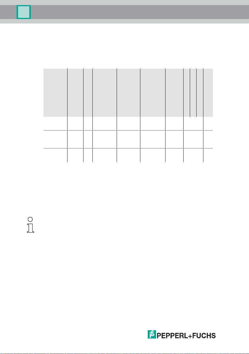
This system manual applies to the following Pepperl+Fuchs GmbH equipment:
1
Artikel Nr.
VBG-ENXK20-DMD-EV
VBG-ENXK20-DMD
VBG-ENXK20-D
1. AS-i Power24V capable.
Art
Schutzart
Schnittstelle, Feldbus
Gateway IP20
Gateway IP20
Gateway IP20
The devices can be operated directly on a 24V (PELV) power supply. The gateway VBG-ENX-K20DMD-EV is optimized with integrated data coupling coils and adjustable self-resetting fuses for
safe use also of powerful 24V power supplies. The gateways VBG-ENX-K20-D and VBG-ENXK20-DMD need to add in Power24V-operation a power supply decoupling unit.
EtherNet/IP +
ModbusTCP
EtherNet/IP +
ModbusTCP
EtherNet/IP +
ModbusTCP
Anzahl AS-i Kreise,
Anzahl der AS-i Master
2 AS-i networks, 2 AS-i
Masters
2 AS-i networks, 2 AS-i
Masters
2 AS-i networks, 2 AS-i
Masters
1 Netzteil, 1 Gateway
für 2 AS-i Kreise,
günstige Netzteile
yes, max. 4A/
AS-i network
no, max. 8A/
AS-i network,
redundant
supply
no, max. 8A/
AS-i network
Diagnose- und
Konfigurationsschnittstelle
Ethernet
Feldbus +
RS 232
Ethernet
Feldbus +
RS 232
Ethernet
Feldbus +
RS 232
Doppeladresserkennung
yes
yes
yes
AS-i Wächter
AS-i Power24V
optio
nal
optio
nal
optio
nal
Tab. 4-1.
The AS-i 3.0 EtherNet/IP+Modbus TCP Gateway serves to connect AS-i systems
to the superordinate Ethernet controller.
Information!
The device uses one of two protokols: EtherNet/IP or Modbus TCP. The selection
takes place in the menu (see chap. <Installati on > ).
Programmierung in C
10
26.9.2013
Page 11

AS-i 3.0 EtherNet/IP+Modbus TCP Gateway
General
4.2 New Generati on of AS-i Gateways with ethernet diagnostics interface The plus points of the new Gateway generation at a glance:
• Gateways now programmable in C
• Ethernet diagnostics interface for remote diagnostics
• Integrated web server: diagnostics for the Gateways and the AS-i circuits
over Ethernet possible with no additional software
• GSD configuration files already stored in the web server
• Earth fault monitor distinguishes between AS-i cable and sensor cable
• Current from both AS-i circuits in the "1 Gateway, 1 power supply for 2 AS-i
circuits" version can now be read directly on the unit
• Self-resetting fuses in the "1 Gateway, 1 power supply for 2 AS-i circuits" ver-
sion
• Device temperature display
• AS-i Power24V capable
• Interfaces for virtually every bus system and Ethernet solution
Information!
See also section <Functions of the new generation of AS-i Gateways> for further information.
4.3 AS-i specification 3.0
The AS-i 3.0 devices already fulfil the AS-i specification 3.0.
The previous specifications (2.1 and 2.0) are supported as well.
Advanced Diagnostics
Diagnostics, which go far beyond the standard diagnostics facilitate the simple
detection of the occasionally occurring configuration errors and further irritations
towards the AS-i communication. So in case of an error the down time of machines can be minimized or you can initiate preventive maintenance.
Commissioning and monitoring
Commissioning, debugging and setting up of the AS-i parameters can also be accomplished with the use of push-buttons on the frontside of the gateway, the display and the LEDs. It is also possible to do the configuration with the software
"AS-i Control Tools".
26.9.2013
11
Page 12

AS-i 3.0 EtherNet/IP+Modbus TCP Gateway
Specifications
5. Specifications
5.1 Technical data
The technical data are placed in the data sheet. Please view the current version
on the web page: http://www.pepperl-fuchs.de.
12
26.9.2013
Page 13
AS-i 3.0 EtherNet/IP+Modbus TCP Gateway
Installation
6. Installation
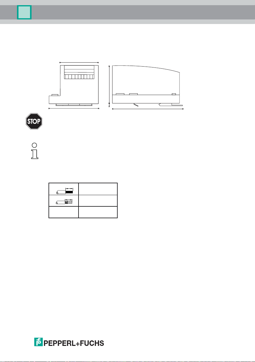
6.1 Dimensions
55
75
Warning!
85
Cover the top of the gateway w h en do ing any drilling work above the un it . N o p articles,
especially metal chips, should be allowed to enter the housing, since this could cause a
short circuit.
Information!
Please refer to installation instruction for this device for detailed mounting information.
6.2 Connections
10
10
AWG 24 ... 12
0,2 ... 2,5 mm
0,2 ... 2,5 mm
7
120
2
2
26.9.2013
13
Page 14
AS-i 3.0 EtherNet/IP+Modbus TCP Gateway
Installation
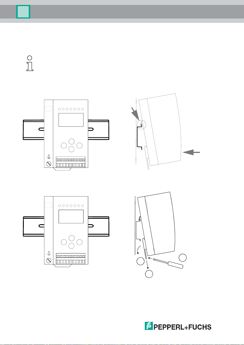
6.3 Installing in the control cabinet
The AS-i/Gateway is installed in the control cabinet on 35mm DIN rails per DIN
EN 50 022.
Information!
The enclosure of the AS-i/Gateway is made of stainless steel. The unit is also suitable
for exposed wall mounting.
To install, place the unit on the upper edge of the DIN rail and then snap in the
lower edge.
-
-
+-+
+
[1]
[2]
6.4 Removing
To remove, press the holding clamps [2] down using a screwdriver [1], press the
unit firmly against the upper rail guide and lift out.
14
-
-
+-+
+
3
1
2
26.9.2013
Page 15
AS-i 3.0 EtherNet/IP+Modbus TCP Gateway
Installation
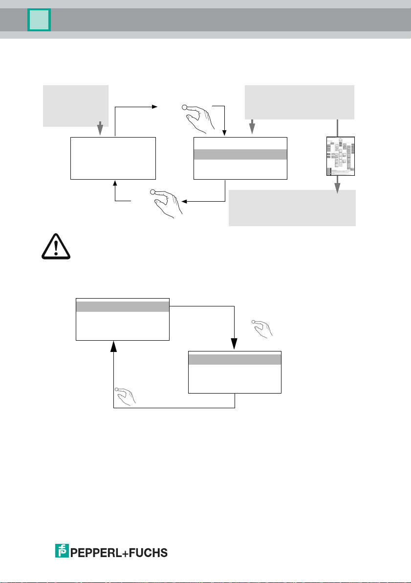
6.5 Commissioning
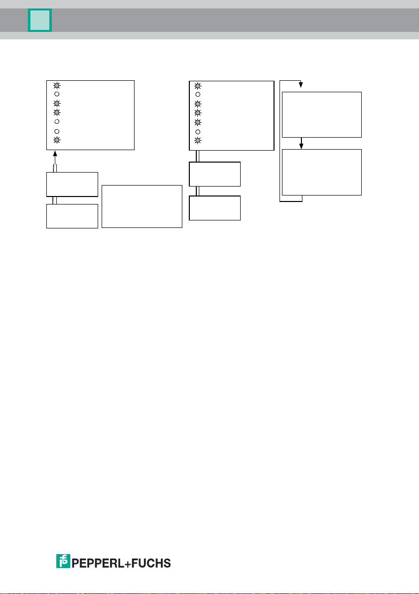
6.5.1
classical display
Switching to advanced display mode
OK
advanced display mode
1.12A
UNKNOWN SLAVE
ESC
The device handels multiple protocols! Please select one of them during the initial
operation.
6.5.2 Select Modbus TCP
ETHERNET
QUICK SETUP
SLAVE ADR. TOOL
SLAVE TEST TOOL
ESC
LCD
ETHERNET
QUICK SETUP
SLAVE ADR TOOL
SLAVE TEST TOOL
menu structure see additional page
OK
MODBUS TCP X
ETHERNET/IP
LCD
26.9.2013
15
Page 16
AS-i 3.0 EtherNet/IP+Modbus TCP Gateway
Installation
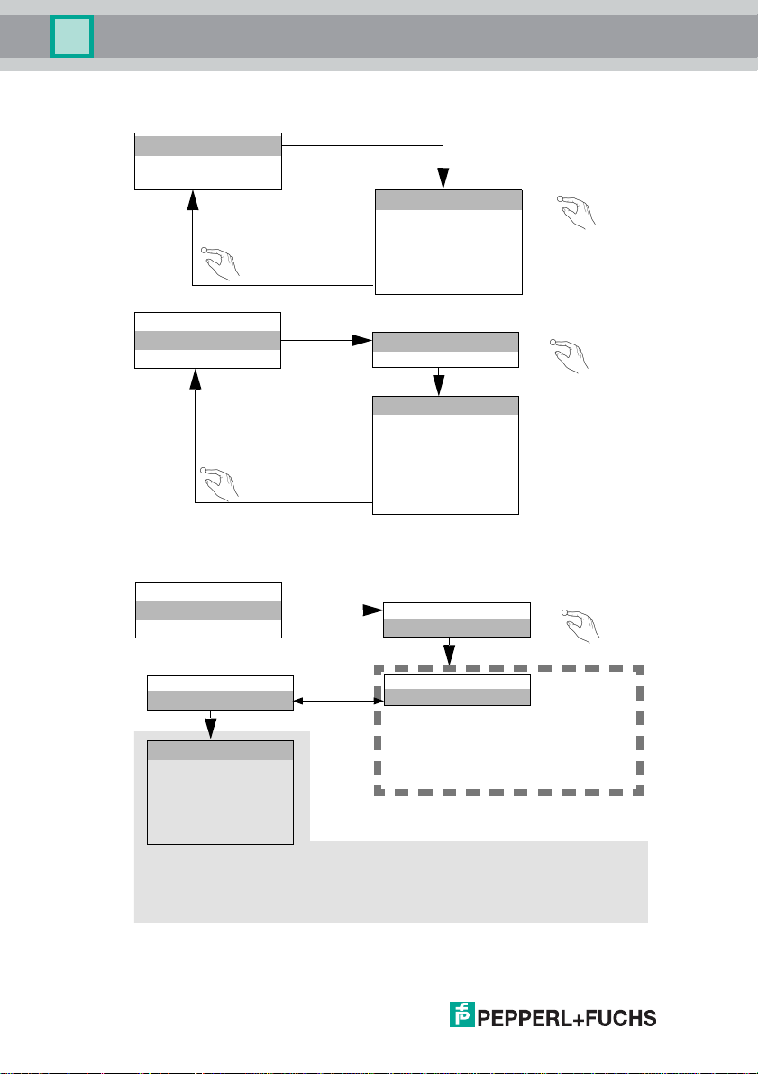
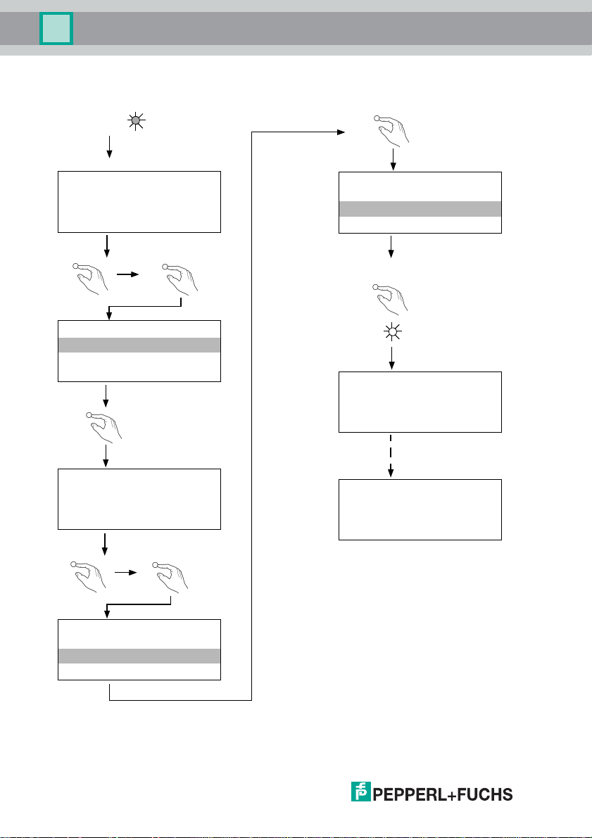
6.5.2.1 Displaying of Ethernet properties
ETHERNET
TCP/IP
MODBUS
ESC
ETHERNET
TCP/IP
MODBUS
ESC
6.5.2.2 Setting of Ethernet properties
ETHERNET
LINK:
100 BASE-TX FDX
MAC ID:
00-16-77-002E-C3
ACTUAL VALUES
CONFIGURATION
ACTUAL VALUES
IP ADDRESS
192. 168. 000.254
NET MASK
255. 255. 255. 0
GATEW AY
0 .0 .0 .0
OK
OK
16
ETHERNET
TCP/IP
MODBUS
CONFIGURATION
STATIC
ACTUAL VALUES
CONFIGURATION
CONFIGURATION
DYNAMIC
When using DHCP, no adjustment is necessary
IP ADDRESS
192. 168. 42. 149
NET MASK
255. 255. 255. 0
GATEWAY
0 . 0 . 0. 0
If you do not have DHCP client access, please contact your network administrator. /
OK
26.9.2013
Page 17
AS-i 3.0 EtherNet/IP+Modbus TCP Gateway
Installation
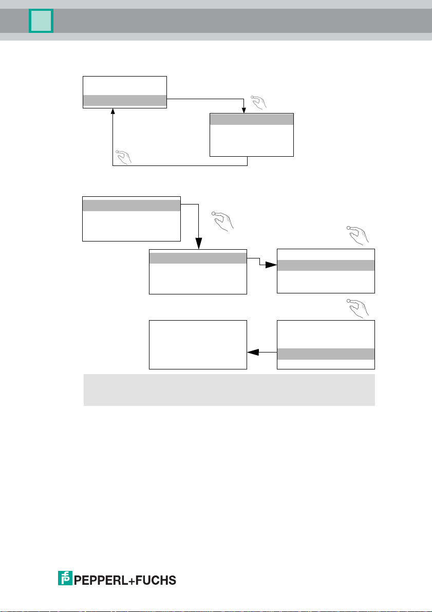
6.5.2.3 Setting of watchdog time
ETHERNET
TCP/IP
MODBUS
WATCHDOG TIME
200
ESC
in 10ms steps
000 = disable
"
6.5.3 Select EtherNet/IP
ETHERNET
QUICK SETUP
SLAVE ADR. TOOL
SLAVE TEST TOOL
MODBUS TCP X
ETHERNET/IP
CHANGES TAKE
EFFECT ON NEXT
POWER ON
Restart the gateway to assume your changes
OK
OK
!
MODBUS TCP
ETHERNET/IP X
ETHERNET/IP
NOT ACTIVE
ACTIVATE IT?
YES
NO
↓
OK
↓
OK
26.9.2013
17
Page 18
AS-i 3.0 EtherNet/IP+Modbus TCP Gateway
Installation
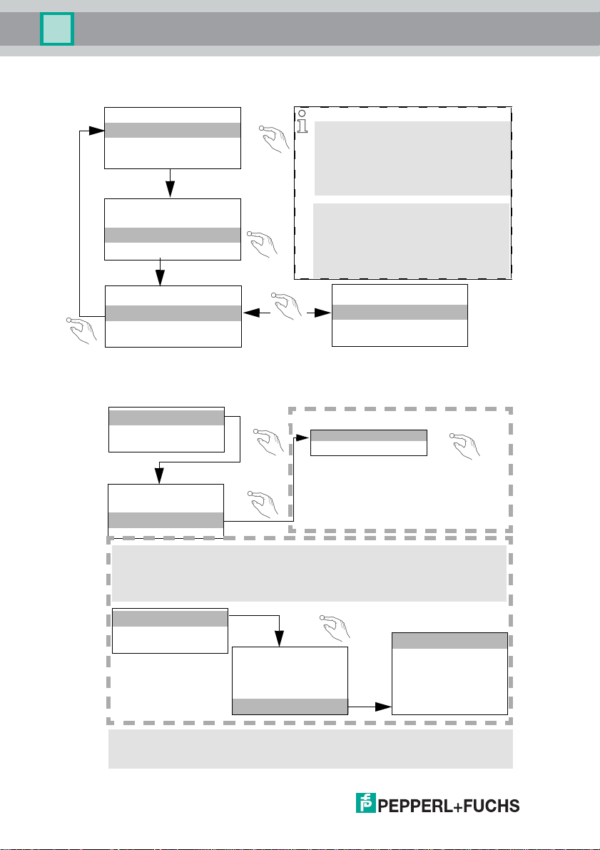
6.5.3.1 Select command interface mode
MODBUS TCP
ETHERNET/IP X
OK
TCP OBJECT
↓
ETHERNET OBJECT
OK
MAILBOX MODE
ESC
MAILBOX MODE
38 BYTE
OK
6.5.3.2 Setting of EtherNet/IP properties
TCP/IP OBJECT
ETHERNET OBJECT
IF STATUS
IF CAPABILITY
IF CONTROL
...
If you do not have DHCP client access, please contact your network administrator. /
OK
↓
MAILBOX MODE
38 Byte:
Enchanced mailbox length for current device revision
36 Byte:
Compatibility mode for older devices
MAILBOX MODE
36 BYTE
USE DHCP
When using DHCP, no adjustment is necessary
OK
18
TCP/IP OBJECT
ETHERNET OBJECT
IF STATUS
IF CAPABILITY
IF CONTROL
PATH TO LINK OBJ.
TCP/IP CONFIG
Restart the gateway to as sume your changes
↓
OK
IP ADDRESS
192. 168. 42. 149
NET MASK
255. 255. 255. 0
GATEWAY
0 . 0 . 0. 0
26.9.2013
Page 19
AS-i 3.0 EtherNet/IP+Modbus TCP Gateway
Installation
6.5.4 Connecting AS-i Slaves
AS-i
power
net
config error
U AS-i
AS-i active
prg enable
prj mode
AS-i Master
AS-i
power
net
config error
U AS-i
AS-i active
prg enable
prj mode
AS-i Master
LCD
1. 1
0.5s
AS-i
Slave 1
AS-i
Slave 5
LCD
1. 41
SEARCHING SLAVES
AS-i
Slave 1
AS-i
Slave 5
1. 5
0.5s
26.9.2013
19
Page 20
AS-i 3.0 EtherNet/IP+Modbus TCP Gateway
Installation
6.6 Q uick setup
config error
1. 5
1xOK
ETHERNET
QUICK SETUP
SETUP
IO + PARAM. TEST
OK
WARNING:
OUTPUTS MAY BE
RESET
OK
LCD
STORE AS-I
CONFIGURATION
OK
STORE +PRJ MODE
↓
2x ESC
LCD
LCD
LCD
.
CONFIGURATION OK
LCD
HOST ERROR
NO CONNECTION
LCD
OK
STORE AS-I
CONFIGURATION
STORE +RUN
STORE +PRJ MODE
20
↓
LCD
26.9.2013
Page 21
AS-i 3.0 EtherNet/IP+Modbus TCP Gateway
Installation
6.7 Error tracing
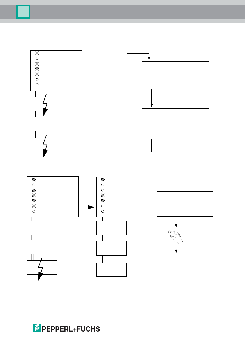
6.7.1 Faulty slaves
power
net
config error
U AS-i
AS-i active
prg enable
AS-i
prj mode
AS-i Master
LCD
1.1
MISSING SLAVE
AS-i
Slave 1
AS-i
Slave 5
AS-i
Slave 24
6.7.2 Error display (last error)
power
net
config error
U AS-i
AS-i active
prg enable
prj mode
AS-i
AS-i
Slave 1
AS-i
Slave 5
AS-i
Slave 24
AS-i Master
power
net
Config error
U AS-i
AS-i active
prg enable
prj mode
AS-Interface
AS-i
Slave 1
AS-i
Slave 5
AS-i
Slave 24
2s
LCD
1.24
MISSING SLAVE
2s
LCD
Host error
no connection
AS-i Master
set/↓
24
26.9.2013
21
Page 22
AS-i 3.0 EtherNet/IP+Modbus TCP Gateway
Installation
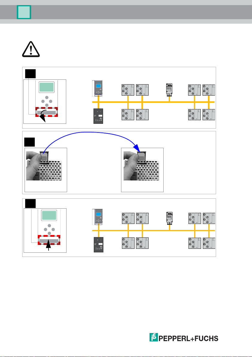
6.7.3 Replacing the chip card
Always turn off power before inserting or removing the card!
[1]
[2]
22
[3]
old
new
26.9.2013
Page 23
AS-i 3.0 EtherNet/IP+Modbus TCP Gateway
Installation
6.7.4 Local parameter setting of AS-i/Gateways
Geräte+Chipdaten ungleich
(Werkskonfiguration geändert)
/Device+card data not equal
(Factory configuartion changed)
Fehlermeldung:
/Error message/
Geräte+Chipdaten gleich
/Device data+card data equal/
Karte leer + formatiert
/Card empty + formatted/
CHIPCARD AND
DATA
DIFFERENT
CARD->MASTER
MASTER->CARD
CONTINUE
Keine Meldung
/No message/
CHIPCARD FOUND
DATA WILL
BE SYNCHRONIZED
Daten werden synchronisiert:
/Data being synchronized/
MASTER->KARTE
Copy data CARD->MASTER
or MASTER->CARD
Daten kopieren
KARTE->MASTER oder
Keine Aktion erforderlich
/No action required/
Keine Aktion erforderlich
/No action required/
Copier données Carte->Maître ou
/Aucune action requise/
/Nessuna azione richiesta/
/Ninguna deción requrida/
/Aucune action requise/
/Nessuna azione richiesta/
/Ninguna deción requrida/
Maître-Carte
Copiare dati Chipcard->Master o
copiare dati Master->Chipcard
Copiar dates Chip->Maestro o
Maestro ->Chip
konfiguration)
DATA FROM
(Werks
/Data compatible (factory
configuration)/
Daten kompatibel
Daten nicht kompatibel
/Data not compatible/
Karte nicht formatiert
/Card not formatted/
26.9.2013
CHIPCARD TAKEN
Daten werden übernommen:
/Data being acepted/
CHIPCARD NOT
COMPATIBLE
Fehlermeldung:
/Error message/
NEW CHIPCARD
WILL BE FORMATTED
DATA WILL BE
/Formatting card /
SYNCHRONIZED
Karte wird formatiert:
Keine Aktion erforderlich
/No action required/
/Aucune action requise/
/Nessuna azione richiesta/
/Ninguna deción requrida/
Karte löschen
/Clear the card/
/Supprimer carte/
/Cancellare chipcard/
/Borrar chip/
Keine Aktion erforderlich
/No action required/
/Aucune action requise/
/Nessuna azione richiesta/
/Ninguna deción requrida/
23
Page 24
AS-i 3.0 EtherNet/IP+Modbus TCP Gateway
Electrical connection
7. Electrical connection
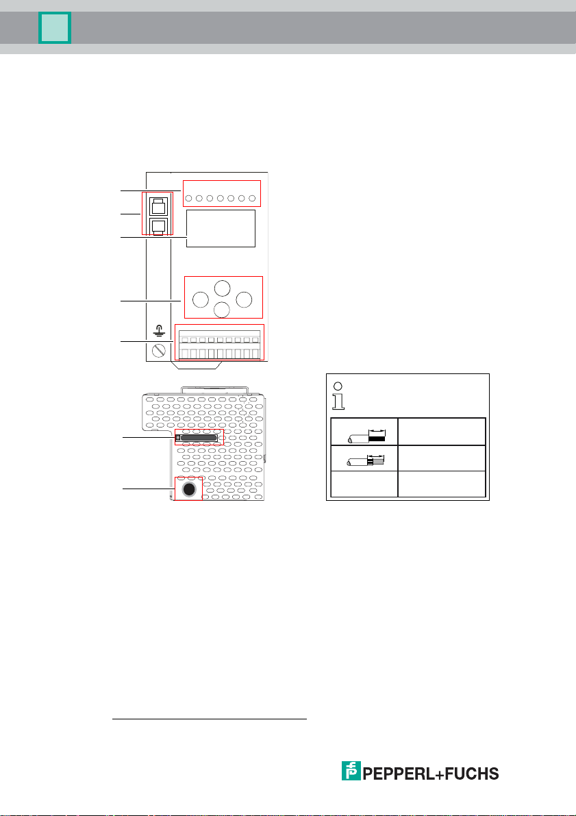
7.1 Overview of terminals, indicators and operating elements
7.1.1 VBG-ENX-K20-D, VBG-ENX-K20-DMD, VBG-ENX-K20-DMD-EV
[1]
[2]
[3]
[4]
[5]
-
+-+
-
+
[6]
[7]
Legend:
[1] LEDs
[2] Ethernet interface
[3] LC display
[4] Buttons
[5] Terminals: Supply voltage and AS-i circuit
[6] Chip card
[7] RS232 diagnostics port
1. Only together with AS-i Control Tools
1
10
0,2 ... 2,5 mm
10
0,2 ... 2,5 mm
AWG 24 ... 12
2
2
26.9.2013
24
Page 25

AS-i 3.0 EtherNet/IP+Modbus TCP Gateway
Electrical connection
7.2 AS-i bus connection
Blue
AS-i-
Brown
AS-i+
Blue
AS-i-
Brown
AS-i+
Yellow ASi ribbon cable
2-conductor AS-i round cable
(Recommended: flexible power cable
H05VV-F2x1,5 per DIN VDE 0281)
Information!
Electrical work is to be performed only by electrical technicians.
7.3 Information about the device types
Information!
A listing of the individual device s and their features can be found in section <Produ ct
information>.
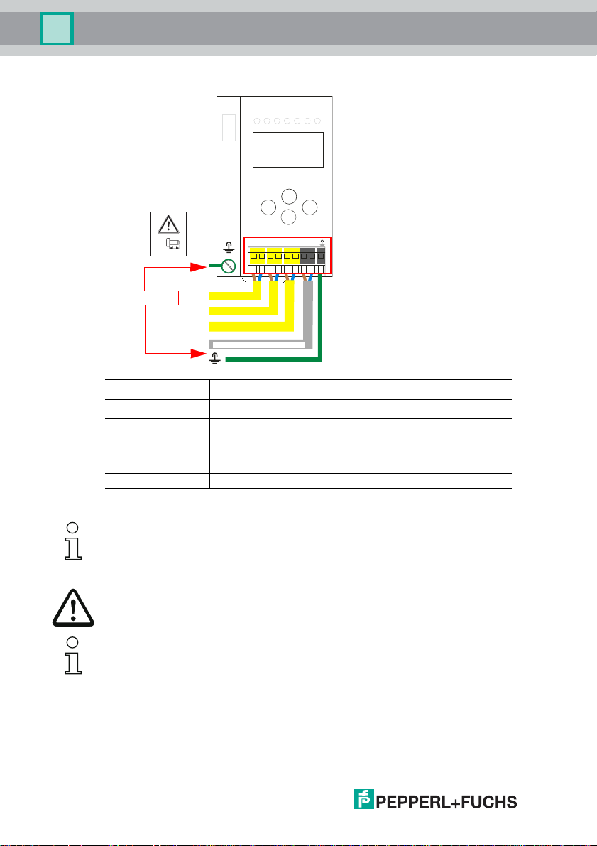
7.4 AS-i and power supply terminal assignments
Information!
The cable indicated by grey must not have slaves or repeaters connected to it.
The yellow cable must not have AS-i po wer supp liers or additional masters co nnecte d
to it.
Information!
The function ground can be connected either to the grounding screw or to the terminal.
The function ground shoul d be made with as s hort a cable a s pos sible to e nsure g ood
EMC characteristics.
Therefore function grounding using the grounding screw is preferred.
26.9.2013
25
Page 26
AS-i 3.0 EtherNet/IP+Modbus TCP Gateway
Electrical connection
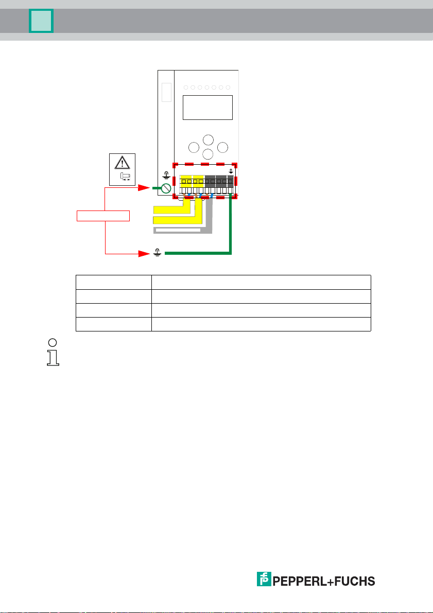
7.4.1 Electrical connection VBG-ENX-K20-D
ASI
+ASI-+ASI
-
-
+PWR
M4
5 mm max!
NC NC
-
-
+-+
+
Function ground
+ASI –
+ASI –
ASI +PWR– (max. 8A)
Terminal Signal / Description
+AS-i–
ASI +PWR–
FE
Connection to AS-i Circuit
Supply voltage for AS-i Circuit (max. 8 A)
Function ground
Information!
For additional information, plea se refer to the sect ion <AS -i and powe r supply t ermin al
assignments>.
26
26.9.2013
Page 27
AS-i 3.0 EtherNet/IP+Modbus TCP Gateway
Electrical connection
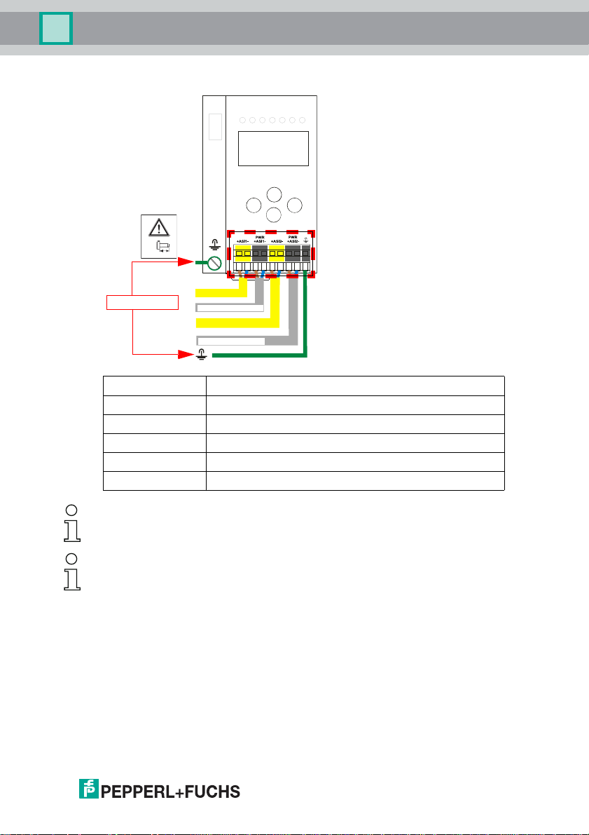
7.4.2 Electrical connection VBG-ENX-K20-DMD
M4
5 mm max!
-
-
+-+
+
Function ground
+ASI 1–
ASI 1 +PWR– (max. 8A)
+ASI 2–
+
ASI 2 +PWR– (max. 8A)
Terminal Signal / Description
+ASI 1–
+ASI 2–
ASI 1 +PWR–
ASI 2 +PWR–
FE
Connection to AS-i circuit1
Connection to AS-i circuit2
Supply voltage for AS-i circui t 1 (max. 8 A)
Supply voltage for AS-i circui t 2 (max. 8 A)
Function ground
Information!
AS-i circuits 1 and 2 are powered by separate power supplies.
Information!
For additional information, plea se refer to the sect ion <AS -i and powe r supply t ermin al
assignments>.
26.9.2013
27
Page 28
AS-i 3.0 EtherNet/IP+Modbus TCP Gateway
Electrical connection
7.4.3 Electrical connection VBG-ENX-K20-DMD-EV
M4
5 mm max!
Function ground
+ASI1- +ASI1- +ASI2-
+ASI 1–
+ASI
1–
2–
+ASI
+
ASI +PWR– (max. 4A) / 24V, 0V
+ASI PWR 24V 0V
-
-
-
+
+-+
+
Terminal Signal / Description
+ASI 1–
+ASI 2–
ASI +PWR– /
24 V, 0 V
Connection to AS-i circuit1
Connection to AS-i circuit2
Supply voltage for AS-i circuits (max. 4 A) /
AS-i Power241 supply optional
FE Function ground
1. The gateway is AS-i Power24V capable and can be operated directly on a 24V (PELV) power supply.
28
Information!
AS-i Circuit 1 and 2 are both powered from a
Bihl+Wiedemann GmbH power sup-
ply!
No other power supplies are approved!
Attention!
Earth fault detector sensor without function when using AS-i Power24!
Information!
For additional information, please refer to the sections: <AS-i and power supply terminal assignments> and <AS-i Power24V capable>.
26.9.2013
Page 29
AS-i 3.0 EtherNet/IP+Modbus TCP Gateway
Electrical connection
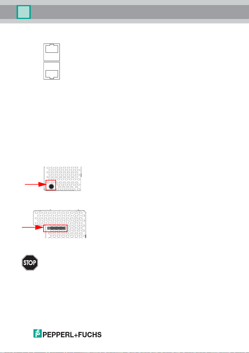
7.5 Ethernet interface
A
B
The ethernet interface consists of two RJ-45 sockets. It is placed on the left housing side (see section <Overview of terminals, indicators and operating elements>). The ethernet interface is driven according to the IEEE 802.3
7.6 Dia gno stics interface
The service and diagnostics interface (in conjunction with AS-i Control Tools
software) is used for communication between the PC and the unit.
7.6.1 Diagnostics port RS 232
The service and diagnostics interface is configured as a mini DIN-6 female and it
is placed at the top of the housing (see section <Overview of terminals, indicators
and operating elements>).
7.7 Chip card
The configuration is stored in a fixed installed EEPROM and can be overwritten
by the chip card. The chip card does not have to be inserted in operation.
Warning!
Power must always be turned off when removing or inserting the chip card!
26.9.2013
29
Page 30

AS-i 3.0 EtherNet/IP+Modbus TCP Gateway
Electrical connection
7.8 Indicators and operating elements
7.8.1 LED indicators – master
net
The LED’s on the front panel of the device indicate:
Power
The master is receiving sufficient power.
net (the bi-color LED indicates the state of the ethernet port)
LED red: no valid ENIP- or CIP connection.
LED green: at least one ENIP- or CIP connection present
config error
Configuration error.
At least one configured slave is missing, or at least one detected slave is not configured, or for at least one configured and detected slave the actual configuration data
does not match the nominal configuration data, or the master is in the startup process.
This LED flashes if a peripheral fault has been detected for at least one AS-i slave
on the AS-i network. If there a re con figurat ion erro rs as w ell as pe ripher y faults , only
the configuration error is displayed.
U AS-i
The AS-i network is sufficiently powered.
AS-i active
Normal operation is active
prg enable
Automatic single node replacem ent is enabled.
Exactly one slave is missing in the protected operating mode. The slave can be
replaced by another slave of the same type with address zero. The master automatically addresses the new slave to the faulty address and thus corrects the configuration error
prj mode
The AS-i master is in configuration mode.
30
26.9.2013
Page 31

AS-i 3.0 EtherNet/IP+Modbus TCP Gateway
Electrical connection
7.8.2 Buttons
The buttons are used for the following:
Mode/⇑
Switching between configuration mode and protected operating mode, and saving
the current AS-i configurati on as the nominal configuration.
Set/⇓
Selecting the address of and assigning an address to a slave.
OK, ESC
Changing to the advanced display mo de.
For additional information see section <Operation in advanced display mode>.
26.9.2013
31
Page 32

AS-i 3.0 EtherNet/IP+Modbus TCP Gateway
Operation in advanced display mode
8. Operation in advanced display mode
Information!
You will find a description of the display menu in the separate document
"Display_Menue".
32
26.9.2013
Page 33

AS-i 3.0 EtherNet/IP+Modbus TCP Gateway
Advanced Diagnostics for AS-i Masters
9. Advanced Diagnostics for AS-i Masters
The advanced AS-i diagnostics is intended to localize occasionally occurring configuration errors and to determine the quality of data transmission on AS-i without
using additional diagnostics tools.
AS-i Control Tools, a MS-Windows software designed to simplify AS-i installation
and used to program AS-i Control, enables operation of the advanced diagnostics
functions (LCS, error counters, and LOS).
9.1 List of corrupted AS-i Slaves (LCS)
The LCS contains the information from the Delta list. In addition to the list of configured slaves (LPS), the list of detected slaves (LDS), and the list of activated
slaves (LAS), the AS-i master creates a fourth list, the list of corrupted slaves
(LCS) containing advanced diagnostics data used to diagnose the causes for intermittently occurring configuration errors on AS-i. This list contains entries for all
AS-i slaves that were responsible for at least one intermittent configuration error
since the list was last read or since the AS-i master was turned on. Furthermore,
intermittent AS-i power failures are listed in the LCS at the position of AS-i slave
with address 0.
Information!
Whenever the LCS is read it is deleted from memory.
Information!
The last intermittent configuration error can also be displaye d on the AS-i master:
Pressing the "Set" button on the AS-i master initiates the display of the AS-i slave
responsible for the last i ntermi ttent con figur ation err or. If a i ntermi ttent AS -i power failure occurred, the display show s 39 after pressing the "Set" button.
This function is only available if the device is in normal ope rating mod e of the prote cted
mode (display empty) or in the off- line phase (Display: "40").
9.2 Protocol analysis: Counters for corrupted data telegrams
The AS-i master with advanced diagnostics provides a counter for telegram repetitions for each AS-i slave. The counter counts up every time a corrupted data telegram has been found, making it possible to determine the quality of the transmission if only a few telegrams are corrupt and the AS-i slave never caused a
configuration error.
Information!
The counter values are read vi a the host inter face and will be de leted after th ey were
read.
The highest possible counter v alue is 254. 255 indicates a counter overflow.
Displaying the protocol analysis is possible through the AS-i Control Tools software by using the command "Master | AS-i Diagnostics".
26.9.2013
33
Page 34

AS-i 3.0 EtherNet/IP+Modbus TCP Gateway
Advanced Diagnostics for AS-i Masters
9.3 Offline Phase for Configuration Errors
The AS-i masters with advanced diagnostics offer the possibility to set themselves into the offline phase when a configuration error occurs and thus are able
to transition the AS-i network into a safe operational state. This ensures a quick
reaction to a configuration error and the host can be relieved from this task. If any
problems occur on the AS-i network, the AS-i masters can independently switch
the AS-interface into a safe state.
There are two different ways to parameterize the AS-i master for this feature:
• Any configuration error occurring on AS-i switches the master from regular
operation in protected mode into the offline phase.
• o . A list with the addresses of slaves that can potential initiate the off-line
phase is defined (list of offline slaves LOS).
The user can decide how the system should react to a configuration error on
AS-i. Thus, the AS-i master can be set to the offline phase for critical AS-i slaves,
whereas for less critical slaves only the error message is sent to the host, but ASi is still running.
Like the advanced diagnostics, the parameterization "offline phase on configuration error" is also supported by "AS-i-Control-Tools"
(Command | Characteristics | Offline because of configuration error).
There are two options to reset the error message "OFFLINE BY LOS:
1. Deleting the complete LOS list on the affected AS-i network ("CLEAR ALL").
2. Power reset on the affected AS-i network.
Attention!
If a power reset occurs on the AS-i network 1 the complete double gateway will
be shut down.
9.4 Functions of the AS-i Fault Detector
9.4.1 Duplicate address detection
If two slaves on an AS-i network have the same address, a duplicate address exists. Since the master cannot communicate individually with these slaves any
longer, this is considered an error. Because the two slave replies interfere, it is impossible for the master to recognize the slave responses. This results in extremely unstable network behavior.
The duplicate address detection function is used to safely recognize a duplicate
address and to display it on the screen and in AS-i Control Tools.
A duplicate address causes a configuration error and is displayed on the screen.
Information!
Duplicate addresses can be recogn ize d onl y on an AS -i seg men t dir ec tly c onn ec ted t o
the master.
34
26.9.2013
Page 35

AS-i 3.0 EtherNet/IP+Modbus TCP Gateway
Advanced Diagnostics for AS-i Masters
9.4.2 Earth/Ground Fault Detector
An Earth/Ground Fault exists when the voltage
=0,5 U
U
GND
10% U
This error substantially limits the noise immunity of the AS-i communication.
Ground faults are indicated on the master´s display as well as in AS-i Control
Tools.
Information!
To recognize ground faults the master must be grounded with its machine ground connection.
Information!
A ground fault in one of the two networks of a double master in a version 1 power supply for two AS-i networks causes a ground fault in the other network as well because of
the the existing galvanic connection.
9.4.3 Noise Detector
The noise detector detects AC voltages on AS-i, that are not initiated by an AS-i
master or AS-i slaves. These interference voltages can cause telegram disturbances.
A frequent cause are insufficiently shielded frequency inverters or improperly
routed cables.
Noises is indicated on the master´s display as well as in AS-i Control Tools.
.) is outside of the following range:
AS-i
≤ U
GND
≤ 90% U
AS-i
AS-i
U
(Nominal value of
GND
9.4.4 Over-voltage Detector
Over-voltages are present if the conductors of an AS-i network that normally are
routed electrically symmetrical with respect to machine ground, are strongly electrically raised. A cause can for example be startup procedures of large consumers.
However, over-voltages do generally not interfere with the AS-i communication,
but can under certain circumstances cause incorrect sensor signals.
Over-voltages are indicated on the master´s display as well as in the AS-i Control
Tools.
26.9.2013
35
Page 36

AS-i 3.0 EtherNet/IP+Modbus TCP Gateway
Advanced Diagnostics for AS-i Masters
9.5 Functions of the new generation of AS-i Gateways
The new generation scores with further optimized diagnostics, several additional
functions and even greater operating convenience.
Information!
A listing of the individual devices and their features can be found in section
Generation of AS-i Gateways with ethernet diagnostics interface>.
9.5.1 C-programmable Gateways
Main menu || SETUP || AS-I CONTROL || CONTROL FLAGS ||
The devices programmed in C are able themselves to take over a great number of
control tasks. In smaller systems the user will even be able to do without a PLC
altogether: if desired the C program can function as a full mini-PLC. In more complex applications the C-programmable Gateways make the work of the PLC easier - for example by pre-processing special functions.
Control Info
Control Run
Control Flags
Control Flags
0:00 00 00 00
4:00 00 00 00
8:00 00 00 00
<New
"
9.5.2 Interchangeable memory card
Main menu || SETUP || CHIPCARD || AS-I CHIPCARD ||
Interchangeable memory card: redundant memory for C program and device configuration.
Chipcard
AS-i Chipcard
Format Chipcard
9.5.3 Earth fault monitor
Main menu || DIAGNOSE || ASI WATCHDOG ||
The new earth fault monitor allows the service technician to detect whether an
earth fault has occurred directly on AS-i
1.
Earth fault
36
26.9.2013
Page 37

AS-i 3.0 EtherNet/IP+Modbus TCP Gateway
Advanced Diagnostics for AS-i Masters
or on a sensor line.
1.
Earth fault sen.
The menu EFLT Ratio shows the asymmetry of the AS-i network, referenced to
ground (see sketch).
100%
0%
100%
%
%
AS-i +
AS-i -
EFLT Ratio: #
AS-i+ 2%
AS-i DC Voltage: 1
31,3V
$
EFLT Ratio: #
AS-i+ 100%
AS-i DC Voltage: 2
31,5V
9.5.4 Current can be read directly on the unit
Now the devices display both the maximum current and the current actually
present in the respective AS-i circuit. Heavy consumers or a strong overload in an
AS-i circuit are then easy to detect. Plus you can set the maximum cu rrent in the
AS-i circuit on these devices. This ensures line protection even when using large
24V power supplies.
AS-i power
Reset
Maximal: 2
1,3A
26.9.2013
"
37
Page 38

AS-i 3.0 EtherNet/IP+Modbus TCP Gateway
Advanced Diagnostics for AS-i Masters
Maximal: #
1,3A
current: 2
0,3A "
Current: #
0,3A
Current limiting 2
3,2A "
9.5.5 Self-resetting fuses
Main menu || SETUP || CURRENT LIMIT ||
Thanks to self-resetting fuses in the "1 Gateway, 1 power supply for 2 AS-i circuits" Gateway version, when there is a short circuit in one of the two AS-i circuits
the other circuit and the Gateway remain operational - the host controller keeps
receiving diagnostic information from AS-i, which also provides meaningful assistance towards rapid troubleshooting.
The fuse resets itself periodically to check if the error is solved. The measured
current value is available as diagnostic information at the field on the display and
at the control level.
9.5.6 AS-i Power24V capable
Main menu || SETUP || ASI POWER ||
Gateways for AS-i Power24V have been developed especially for use in small
systems. They don‘t need any special AS-i power supply. With a standard 24V
power supply a 50 m line lenght and with an AS-i power supply min. 100 m line
lenght can be realised.
38
Current limiting
3,2A
2
AS-i Power
24V geerdet
change
26.9.2013
Page 39

AS-i 3.0 EtherNet/IP+Modbus TCP Gateway
Advanced Diagnostics for AS-i Masters
AS-i Power
AS-i PWR Supply
change
9.5.7 Ethernet diagnostics interface with web server
These devices allow diagnostics for both the Gateway and the AS-i networks (including Safety technology) over Ethernet without additional software. AS-i network can be thus a part of a remote maintenance concept. Morover the configuration file are stored on the web server and so they are always within reach.
9.5.8 Transitionless operating mode changes
Main menu || SETUP || MODE CHANGE ||
These devices are able to change the operating mode from projecting mod e to
the protected operating mode without having to first go to the "offline phase".
This means the Slave outputs are not cleared and the safe Slaves not turned off.
Activation and deactivation is set using the Ethernet start parameterization.
This function must be explicitly activated; the default setting is “Deactivated.”
The setting for activated and deactivated is saved, which means that it remains
set after a "power cycle".
Mode Change
Offline Phase
yes
change
26.9.2013
39
Page 40

AS-i 3.0 EtherNet/IP+Modbus TCP Gateway
EtherNet/IP interface
10. EtherNet/IP interface
Objekt modelling
The attributes of bus participants are mapped into objects in the CIP family (DeviceNet, ControlNet and EtherNet/IP) bus systems.
In addition to for all EtherNet/IP devices common objects, there are other objects
in the AS-i gateways to access the data of the AS-i network:
• Identity
• Assembly
• AS-i master
• AS-i slave
• I/O data
• Advanced diagnostics
• Short command interface
• Long command interface
• Safety Control Status (external)
Class code Object name Number of instances
0x01 Identity 1
0x02 Message router 1
0x04 Assembly 24 (single master)
0x06 Connection manager 1
0x47 Device level ring 1
0x48 Quality of service 1
0x64 AS-i master 1 for each AS-i circuit
0x65 AS-i slave 64 for each AS-i circuit
0x66 E/A data 1 for each AS-i circuit
0x67 Advanced diagnos ics 1 for each AS-i circuit
0x68 Short command interface 1
0x69 Long command interface 1
0x6B Safety Control Status external Mo nitor 1 for each AS-i circuit
86 (double master)
Tab. 10-2.
40
26.9.2013
Page 41

AS-i 3.0 EtherNet/IP+Modbus TCP Gateway
EtherNet/IP interface
10.1 Identity object
class code: 1 (0x01)
number of instanzes: 1
instance attributes
Attribute ID Access Rule Name Value
1 get vendor 5
2 get device type 12
3 get product code e. g.: "2386" (double master)
4 get revision 1.1
5 get status see overwiev listed below
6 get serial number unique number, 32-bit
7 get product name e. g.: "VBG-ENX-K20-D"
Common services
Service Code Class Instance Service name
0x05 no yes code 1
(class + instance)
0x10 yes yes get attributes all
0x0E yes yes get attributes all
e. g.: "2385" (single master)
Tab. 10-3.
Tab. 10-4.
26.9.2013
41
Page 42

AS-i 3.0 EtherNet/IP+Modbus TCP Gateway
EtherNet/IP interface
10.2 Device Level Ring Object
Class Code: 71 (0x47)
number of instanzes: 1
instance attributes
Attribute ID Access Rule Name Value
1 (0x01) get network topo-
logy
2 (0x02) get network status 0 (normal), 1 (ring fault)
10 (0x0E) get active supervi-
sor address
12 (0x0C) get capability flags 1 (announce-based ring node)
Common Services
Service Code Class Instance Service Name
1 (0x01) yes yes get attributes all
14 (0x0E) yes yes get attribute single
0 (linear), 1 (ring)
byte 0-3: ip-adress,
byte 4-9: mac-adress
Tab. 10-5.
Tab. 10-6.
42
26.9.2013
Page 43

AS-i 3.0 EtherNet/IP+Modbus TCP Gateway
EtherNet/IP interface
10.3 Quality of Service Object
Class Code: 72 (0x48)
number of instanzes: 1
instance attributes
Attribute ID Access Rule Name Value
1 (0x01) get/set 802.1q tag
enable
4 (0x04) get/set dscp urgent dscp after rfc 3168 for cip class 0/1
5 (0x05) get/set dscp scheduled dscp after rfc 3168 for cip class 0/1
6 (0x06) get/set dscp high dscp after rfc 3168 for cip class 0/1
7 (0x07) get/set dscp low dscp after rfc 3168 for cip class 0/1
8 (0x08) get/set dscp explicit dscp after rfc 3168 for cip class 3/
Common Services
0 (disabled), 1 (enabled)
urgent (default 55)
scheduled (default 47)
high (default 43)
low (default 31)
ucmm (default 27)
Tab. 10-7.
Service Code Class Instance Service Name
14 (0x0E) no yes get attributes single
16 (0x10) no yes get attribute single
Tab. 10-8.
Information!
The new settings take effect only after a device restart.
Information!
If “802.1Q Tag Enable“ is tu rn ed o n, the VL AN ID s et i n the de vi ce me nu “E th erne t“ - >
“EtherNet/IP“ -> “VLAN ID“ is used.
Information!
The integrated switch uses four internal priority queues.
Information!
The VLAN ID is only used if in the EtherNet/IP Quality of Service Object (0x48)
Attribute 1 (802.1Q Tag Enable) is se t to 1 (= ON), so th at Et hernet frames ar e sent in
accordance with IEEE 802.1Q.
26.9.2013
43
Page 44

AS-i 3.0 EtherNet/IP+Modbus TCP Gateway
EtherNet/IP interface
Mapping of the SDCP and 802.1D priorities to the queues is as follows:
Switch queue DSCP 802.1D priority
4 (highest priority) 59 7
3 46, DSCP Urgent, DSCP Scheduled,
DSCP High
2 24, DSCP Low, DSCP Explicit 2,3
1 (lowest priority) other values 0,1
4, 5, 6
Tab. 10-9.
44
26.9.2013
Page 45

AS-i 3.0 EtherNet/IP+Modbus TCP Gateway
EtherNet/IP interface
10.4 Assembly Object
class code 4 (0x04)
number of instances: 86
The Assembly Object bandles data from the application objects.
The Assembly Object Instances consist of (in case of a double master):
• A-slaves and/or single slaves from circuit 1
• single, A- and B-slaves (all slaves) from circuit 1
• A-slaves and/or single slaves from both circuits
• single, A- and B-slaves (all slaves) from both circuits
• No 16-bit data
• No command interface
• Short command interface
• Long command interface
• 16-bit data of slaves 29…31 from circuit 1 (or from both circuits) in the following format:
16-bit data of slaves 29 … 31
byte data item (attribute ID=3)
n Slave 31 ch1 high byte
n+1 Slave 31 ch1 low byte
n+2 Slave 31 ch2 high byte
n+3 Slave 31 ch2 low byte
n+4 Slave 31 ch3 high byte
n+5 Slave 31 ch3 low byte
n+6 Slave 31 ch4 high byte
n+7 Slave 31 ch4 low byte
n+8 Slave 30 ch1 high byte
n+9 Slave 30 ch1 low byte
n+10 Slave 30 ch2 high byte
n+11 Slave 30 ch2 low byte
n+12 Slave 30 ch3 high byte
n+13 Slave 30 ch3 low byte
n+14 Slave 30 ch4 high byte
n+15 Slave 30 ch4 low byte
n+16 Slave 29 ch1 high byte
n+17 Slave 29 ch1 low byte
n+18 Slave 29 ch2 high byte
n+19 Slave 29 ch2 low byte
26.9.2013
Tab. 10-10.
45
Page 46

AS-i 3.0 EtherNet/IP+Modbus TCP Gateway
EtherNet/IP interface
16-bit data of slaves 29 … 31
n+20 Slave 29 ch3 high byte
n+21 Slave 29 ch3 low byte
n+22 Slave 29 ch4 high byte
n+23 Slave 29 ch4 low byte
Instances 100 (0x64)…135 (0x87) can only be read, while instances 136
(0x88) …171 (0xAB) can be read and written.
Information!
The are only instances 100 (0x64) … 105 (0x69) and 109 (0x6D) … 114 (0x72) in case
of a single master.
Tab. 10-10.
46
26.9.2013
Page 47

AS-i 3.0 EtherNet/IP+Modbus TCP Gateway
EtherNet/IP interface
Assembly Instance Data Item
input output size
100 (0x64) 136 (0x88) 16
101 (0x65) 137 (0x89) 28 short
102 (0x66) 138 (0x8A) 54 long
103 (0x67) 139 (0x8B) 40
104 (0x68) 140 (0x8C) 52 short
105 (0x69) 141 (0x8D) 78 long
106 (0x6A) 142 (0x8E) 64
107 (0x6B) 143 (0x8F) 76 short
108 (0x6C) 144 (0x90) 102 long
109 (0x6D) 145 (0x91) 32
110 (0x6E) 146 (0x92) 44 short
111 (0x6F) 147 (0x 93) 70 long
112 (0x70) 148 (0x94) 56
113 (0x71) 149 (0x95) 68 short
114 (0x72) 150 (0x96) 94 long
115 (0x73) 151 (0x97) 80
116 (0x74) 152 (0x98) 92 short
117 (0x75) 153 (0x99) 118 long
118 (0x76) 154 (0x9A) 32
119 (0x77) 155 (0x9B) 44 short
120 (0x78) 156 (0x9C) 70 long
121 (0x79) 157 (0x9D) 56
122 (0x7A) 158 (0x9E) 68 short
123 (0x7B) 159 (0x9F) 94 long
124 (0x7C) 160 (0xA0) 80
125 (0x7D) 161 (0xA1) 92 short
126 (0x7E) 162 (0xA2) 118 long
127 (0x7F) 163 (0xA3) 64
128 (0x80) 164 (0xA4) 76 short
129 (0x81) 165 (0xA5) 102 long
130 (0x82) 166 (0xA6) 88
131 (0x83) 167 (0xA7) 100 short
132 (0x84) 168 (0xA8) 126 long
133 (0x85) 169 (0xA9) 112
134 (0x86) 170 (0xAA) 124 short
135 (0x87) 171 (0xAB) 150 long
digital analog command inter-
(byte)
AS-i circuit 1,
single- and A-slaves
AS-i circuit 1,
all slaves
AS-i circuit 1+2,
single- and A-slaves
AS-i circuit 1+2,
all slaves
AS-i circuit 1,
analog slaves 29 .. 31
AS-i circuit 1+2,
analog slaves 29 .. 31
AS-i circuit 1,
analog slaves 29 .. 31
AS-i circuit 1+2,
analog slaves 29 .. 31
AS-i circuit 1,
analog slaves 29 .. 31
AS-i circuit 1+2,
analog slaves 29 .. 31
AS-i circuit 1,
analog slaves 29 .. 31
AS-i circuit 1+2,
analog slaves 29 .. 31
face
Tab. 10-11.
26.9.2013
47
Page 48

AS-i 3.0 EtherNet/IP+Modbus TCP Gateway
EtherNet/IP interface
10.5 AS-i Master Object
class code: 100 (0x64)
1 instance for each AS-i circuit
attribute
ID
100 (0x64) get ec-flags UINT (16-bit)
101 (0x65) get/set hi-flags USINT
102 (0x66) get/set operational mode BOOL
103 (0x67) get LDS (list of detected slaves) ULINT
104 (0x68) get/set LPS (list of projected slaves) ULINT
105 (0x69) get LAS (list of activated slaves) ULINT
106 (0x6A) get LPF (list of peripheral faults) ULINT
107 (0x6B) get/set Store_Actual_Configuration BOOL
108 (0x6C) get/set Store_Actual_Parameters BOOL
109 (0x6D) get/set Change_Slave_Adress UINT
110 (0x6E) get/set Lock push-buttons BOOL
EC-flags (16-bit)
2152142132122112102928272625242322212
DA NSE OV EF – – – Pok OR APF NA CA AAv AAs S0 Cok
access rule name devicenet data
type
default data
value
Tab. 10-12.
Tab. 10-13.
DA (double_address): AS-i duplicate address detection
0: no duplicate address
1: duplicate address
NSE (noise): AS-i noise detection
0: no noise
1: noise fault
OV (overvoltage): AS-i overvoltage detection
0: no overvoltage
1: overvoltage fault
EF (earth_fault): AS-i earth fault detection
0: no earth fault
1: earth fault
PoK (periphery_ok): Periphery is OK
0: Periphery is OK
1: Periphery is not OK
OR (offline_ready: The off-line phase is active
APF (ASi-power_fail): An AS-i power fail is occured
NA (normal_operation_active) : The normal operation mode is active
0: normal operation is active
1: normal operation is not active
0
26.9.2013
48
Page 49

AS-i 3.0 EtherNet/IP+Modbus TCP Gateway
EtherNet/IP interface
CA (configuration_active): The configuration -mode is active
AAv (Auto_Address_Available): Automatic programming is possible
0: Auto-address is possible
1: Auto-address is not possible
AAs (Auto_Address_Assign): Automatic programming i s allowed
S0 (LDS.0): There is an AS-i slave with address ’0’
Cok (config_ok): Configuration error:
0: no error
1: error
Hi-flags (8-bit)
2
1
2
AAe OL DX
AAe: Auto_Address_Enable
OL: Off-line
DX: Data_Exchange_Active
Operational mode (8-bit):
1: configuration mode
0: protected mode
0
2
2
Tab. 10-14.
LDS, LAS, LPS, LPF (64-bit)
7
6
5
4
3
2
1
Byte
2
2
2
2
2
2
2
0
2
0 7A6A5A4A3A2A1A0A
……
7 31B 30B 29B 28B 27B 26B 25B 24B
Tab. 10-15.
LDS: list of dete ct ed slaves
LAS: list of activated slaves
LPS: list of activated slaves
LPF: list of peri ph eral faults
26.9.2013
49
Page 50

AS-i 3.0 EtherNet/IP+Modbus TCP Gateway
EtherNet/IP interface
Store actual parameter/store actual configuration/lock push-buttons
True: proceed the action
Change slave address (16-bit)
7
6
5
4
3
2
Byte
2
2
2
2
2
0 – B source address
1 – B target address
Meaning of the bit B
B = 0: Single AS-i Slave or A-slave
B = 1: B-slave
1
2
2
2
0
Tab. 10-16.
50
26.9.2013
Page 51

AS-i 3.0 EtherNet/IP+Modbus TCP Gateway
EtherNet/IP interface
10.6 AS-i slave Object
class code: 101 (0x65)
64 instances for each AS-i circuit, 1 for each AS-i slave
instance ID AS-i slave
1 (0x01) slave 0, circuit 1
2 (0x02) slave 1A, circuit 1
……
32 (0x20) slave 31A circuit 1
33 (0x21) empty, circuit 1
34 (0x22) slave 1B, circuit
……
64 (0x40) slave 31B, circuit 1
65 (0x41) slave 0, circuit 2
……
96 (0x60) slave 31A, circuit 2
97 (0x61) empty, circuit 2
……
98 (0x62) slave 1B, circuit 2
……
128 (0x80) slave 31B, circuit 2
Tab. 10-17.
attributeIDaccess
100 (0x64) get actual configuration UINT
101 (0x65) get/set permanent configuration UINT slave 0, 32: not read-/writea102 (0x66) get/set actual parameters USINT
103 (0x67) get/set permanent parameters USINT
104 (0x68) get/set xID1 USINT slave 0: writeable only,
actual configuration/permanent configuration (16-bit)
2152142132122112102928272625242322212
ID IO xID2 XID1
parameter xID1 (8-bit)
272625242322212
–data
26.9.2013
rule
name devicenet
data type
0
remark
ble
slave 0 - 32: readable
Tab. 10-18.
0
Tab. 10-19.
Tab. 10-20.
51
Page 52

AS-i 3.0 EtherNet/IP+Modbus TCP Gateway
EtherNet/IP interface
10.7 I/O Data Object
class code: 102 (0x66)
Input and output data
1 instance for each AS-i circuit
Instance 1 equates to AS-i circuit 1
Instance 2 equates to AS-i circuit 2
attribute IDaccess rule name devicenet data typedefault data
100 get input data image, single and A-slaves ARRAY[16] of
101 get input data image, B-slaves ARRAY[16] of
102 get/set output data image single and A-slavesARRAY[16] of
103 get/set output data image, B-slaves ARRAY[16] of
104 get 16-bit input data slave 1 ARRAY[4] of INT
……… … …
134 get 16-bit input data slave 31 ARRAY[4] of INT
135 get/set 16-bit output data slave 1 ARRAY[4] of INT
……… … …
165 get/set 16-bit output data slave 31 ARRAY[4] of INT
value
USINT
USINT
USINT
USINT
Tab. 10-21.
52
26.9.2013
Page 53

AS-i 3.0 EtherNet/IP+Modbus TCP Gateway
EtherNet/IP interface
Input and Output Data Image
Byte
7
2
F3 F2 F1 F0
0 flags slave 1/1A
1 slave 2/2A slave 3/3A
2 slave 4/4A slave 5/5A
3 slave 6/6A slave 7/7A
4 slave 8/8A slave 9/9A
5 slave 10/10A slave 11/11A
6 slave 12/12A slave 13/13A
7 slave 14/14A slave 15/15A
8 slave 16/16A slave 17/17A
9 slave 18/18A slave 19/19A
10 slave 20/20A slave 21/21A
11 slave 22/22A slave 23/23A
12 slave 24/24A slave 25/25A
13 slave 26/26A slave 27/27A
14 slave 28/28A slave 29/29A
15 slave 30/30A slave 31/31A
16 reserved slave 1B
17 slave 2B slave 3B
18 slave 4B slave 5B
19 slave 6B slave 7B
20 slave 8B slave 9B
21 slave 10B slave 11B
22 slave 12B slave 13B
23 slave 14B slave 15B
24 slave 16B slave 17B
25 slave 18B slave 19B
26 slave 20B slave 21B
27 slave 22B slave 23B
28 slave 24B slave 25B
29 slave 26B slave 27B
30 slave 28B slave 29B
31 slave 30B slave 31B
6
2
5
2
4
2
2
3
2
2
1
2
0
2
Tab. 10-22.
26.9.2013
53
Page 54

AS-i 3.0 EtherNet/IP+Modbus TCP Gateway
EtherNet/IP interface
Flags
Input data Output data
F0 ConfigError Off-line
F1 APF LOS-master-bit
F2 PeripheryFault → ConfigurationMode
F3 ConfigurationActive → ProtectedMode
ConfigError: 0=ConfigOK 1=ConfigError
APF: 0=AS-i-Power OK 1=AS-i-Power Fail
PeripheryFault: 0=PeripheryOK 1=PeripheryFault
ConfigurationActive: 0=ProtectedOperationMode 1=ProjectingMode
Off-Line: 0=On-Line 1=Off-Line
LOS-master-bit 0=Off-Line by ConfigError
deactivated
16-bit data
Information!
A-slaves map the data on channels 1 and 2.
B-slaves map the data on channels 3 and 4.
1=Off-Line by ConfigError
activated.
Tab. 10-23.
54
In addition to the access via the command interfaces, the 16-bit data for or by the
slaves with 16-bit value can by exchanged cyclically (profile 7.3., S-7.4, S-6.0, S-
7.5, S-7.A.8, S-7.A.9, S-7.A.A). Competing writing access attemps on 16-bit output data will not be blocked by every other. If 16-bit output data for a particular
slave are being transmitted both cyclically and acyclically with the command interface, the acyclically transmitted values will be overwritten by the cyclically transmitted values.
Data of all channels of a slave can be transmitted in a reserved data area. Therefore accessing 16-bit data is as easy as accessing digital data.
16-bit value
Word 2152142132122112102928272625242322212
D15 D14 D13 D12 D11 D10 D9 D8 D7 D6 D5 D4 D3 D2 D1 D0
1 slave X, channel 1
2 slave X, channel 2
3 slave X, channel 3
4 slave X, channel 4
Tab. 10-24.
0
26.9.2013
Page 55

AS-i 3.0 EtherNet/IP+Modbus TCP Gateway
EtherNet/IP interface
10.8 Advanced Diagnostics Object
class code: 103 (0x67)
1 instance for each AS-i circuit
Instance 1 equates to AS-i circuit 1
Instance 2 equates to AS-i circuit 2
attributeIDaccess
100 (0x64) Get/Set LOS (List of offline slaves) ULINT
101 (0x65) Get error counter A ARRAY[32] of USINT
102 (0x66) Get error counter B ARRAY[32] of USINT
rule
name devicenet
data type
Slave error counter:
single and A slaves
Index e rro r counter
1 slave 1/1A
2 slave 2/2A
3 slave 3/3A
……
31 slave 31/31A
B slaves
index error counter
1slave 1B
2slave 2B
3slave 3B
……
31 slave 31B
default
data value
Tab. 10-25.
Tab. 10-26.
Tab. 10-27.
26.9.2013
55
Page 56

AS-i 3.0 EtherNet/IP+Modbus TCP Gateway
EtherNet/IP interface
10.9 Short Command Interface Object
class code: 104 (0x68)
1 instance
attributeIDaccess
100 (0x64) get/set content ARRAY[12] of USINT
rule
name devicenet
command [0]
toggle-bit and AS-i circuit [1]
data [2 … 11]
10.10 Long Command Interface Object
class code: 105 (0x69)
1 instance
attributeIDaccess
100 (0x64) get/set content ARRAY [38] of USINT
rule
name devicenet
command [0]
toggle-bit and AS-i circuit [1]
data [2 … 37]
For special details acc. the command interface commands see the separat manual "AS-i 3.0 Command Interface".
data type
data type
default
data value
default
data value
Tab. 10-28.
Tab. 10-29.
56
26.9.2013
Page 57

AS-i 3.0 EtherNet/IP+Modbus TCP Gateway
EtherNet/IP interface
10.11 Safety Control/Status
10.11.1 External Monitor
10.11.1.1 Safety Control Status external Monitor
class code: 107 (0x6B)
1 instance per AS-i circuit
attributeIDaccess
100 (0x64) get slave 1: ARRAY [8] of USINT
……… … …
130 (0x82) get slave 31: ARRAY [8] of USINT
131 (0x83) get/set safety control slave1 USINT
……… … …
161 (0xA1) get/set safety control slave31 USINT
rule
name devicenet
safety status release circuit 1 [0]
safety status release circuit 2 [1]
…[2… 6]
safety status, release circuit8 [7]
safety status release circuit 1 [0]
safety status release circuit 2 [1]
…[2… 6]
safety status release circuit 8 [7]
data type
default
data value
Tab. 10-30.
Coding of states and colors see tab. <Coding of status bytes per OSSD>.
Safety control
Byte description
1 byte from the EtherNet/IP
bit 0: 1.Y1
bit 1: 1.Y2
bit 2: 2.Y1
bit 3: 2.Y2
bit 4 ... 7: reserved
Set (data write access)
The bits of the output byte s whic h hav e bee n set vi a t he host int erface are O Red wi th
the real and the homonymous hardware inputs of the device.
GET (data read access)
The information-bits of t he outputs 1.Y1, 1.Y 2, 1.Y2 and 2.Y2 which h ave been read
back only reflect the data bits set via the host interface.
26.9.2013
57
Page 58

AS-i 3.0 EtherNet/IP+Modbus TCP Gateway
EtherNet/IP interface
Coding of status bytes per OSSD
Bit [0 ... 3] State or. color
00
01
02
03
04
05
06
07
Bit [6] status or color
0 no device flashing yellow
1 at least one device flashing yellow
Bit [7] status or color
0 no device flashing red
1 at least one device flashing red
green permanent lighting
16
green flashing
16
yellow permanent lighting
16
yellow flashing
16
red permanent lighting
16
red flashing
16
grey or off
16
reserved
16
Tab. 10-31.
58
26.9.2013
Page 59

AS-i 3.0 EtherNet/IP+Modbus TCP Gateway
The Modbus Address Table
11. The Modbus Address Table
Cyclic data exchange similar to the Momentum Ethernet Adapter
AS-i circuit 1: Input Data Image IDI
4x
contact read access
reference
bit value
„bit“ 12345678910111213141516
1 1 - 16 F1 F2 F3 F4 F5 F6 F7 F8 F9 F10 F11 F12 F13 F14 F15 F16
2 17 - 32 slave 0/0A slave 1/1A slave 2/2A slave 3/3A
3 33 - 48 slave 4/4A slave 5/5A slave 6/6A slave 7/7A
4 49 - 66 slave 8/8A slave 9/9A slave 10/10A slave 11/11A
5 65 - 80 slave 12/12A slave 13/13A slave 14/14A slave 15/15A
6 81 - 96 slave 16/16A slave 17/17A slave 18/18A slave 19/19A
7 97 - 112 slave 20/20A slave 21/21A slave 22/22A slave 23/23A
8 113 - 128 slave 24/24A slave 25/25A slave 26/26A slave 27/27A
9 129 - 144 slave 28/28A slave 29/29A slave 30/30A slave 31/31A
10 145 - 160 not used slave 1B slave 2B slave 3B
11 161 - 176 slave 4B slave 5B slave 6B slave 7B
12 177 - 192 slave 8B slave 9B slave 10B slave 11B
13 193 - 208 slave 12B slave 13B slave 14B slave 15B
14 209 - 224 slave 16B slave 17B slave 18B slave 19B
15 225 - 240 slave 20B slave 21B slave 22B slave 23B
16 241 - 256 slave 24B slave 25B slave 26B slave 27B
17 257 - 272 slave 28B slave 29B slave 30B slave 31B
F1 - F16: flags, see tab. <Reference 1>.
2152142132122112102928272625242322212
D0 D1 D2 D3 D0 D1 D2 D3 D0 D1 D2 D3 D0 D1 D2 D3
0
Tab. 11-32.
26.9.2013
59
Page 60

AS-i 3.0 EtherNet/IP+Modbus TCP Gateway
The Modbus Address Table
Cyclic data exchange similar to the Momentum Ethernet Adapter
AS-i circuit 2: Input Data Image IDI
4x
contact read access
reference
bit value
„Bit“ 12345678910111213141516
18 273 - 288F1F2F3F4F5F6F7F8F9F10F11F12F13F14F15F16
19 289 - 304 slave 0/0A slave 1/1A slave 2/2A slave 3/3A
20 305 - 320 slave 4/4A slave 5/5A slave 6/6A slave 7/7A
21 321 - 336 slave 8/8A slave 9/9A slave 10/10A slave 11/11A
22 337 - 352 slave 12/12A slave 13/13A slave 14/14A slave 15/15A
23 353 - 368 slave 16/16A slave 17/17A slave 18/18A slave 19/19A
24 369 - 384 slave 20/20A slave 21/21A slave 22/22A slave 23/23A
25 385 - 400 slave 24/24A slave 25/25A slave 26/26A slave 27/27A
26 401 - 416 slave 28/28A slave 29/29A slave 30/30A slave 31/31A
27 417 - 432 not used slave 1B slave 2B slave 3B
28 433 - 448 slave 4B slave 5B slave 6B slave 7B
29 449 - 464 slave 8B slave 9B slave 10B slave 11B
30 465 - 480 slave 12B slave 13B slave 14B slave 15B
31 481 - 496 slave 16B slave 17B slave 18B slave 19B
32 497 - 512 slave 20B slave 21B slave 22B slave 23B
33 513 - 528 slave 24B slave 25B slave 26B slave 27B
34 529 - 544 slave 28B slave 29B slave 30B slave 31B
F1 - F16: flags, see tab. <Reference 1>.
2152142132122112102928272625242322212
D0 D1 D2 D3 D0 D1 D2 D3 D0 D1 D2 D3 D0 D1 D2 D3
0
Tab. 11-33.
60
26.9.2013
Page 61

AS-i 3.0 EtherNet/IP+Modbus TCP Gateway
The Modbus Address Table
Cyclic data exchange similar to the Momentum Ethernet Adapter
AS-i circuit 1: Output Data Image ODI
4x
contact write access
reference
bit value
„Bit“ 1 2 3 4 5 6 7 8 9 10 11 12 13 14 15 16
1 1 - 16 F1 F2 F3 F4 F5 F6 F7 F8 F9 F10 F11 F12 F13 F14 F15 F16
2 17 - 32 slave 0/0A slave 1/1A slave 2/2A slave 3/3A
3 33 - 48 slave 4/4A slave 5/5A slave 6/6A slave 7/7A
4 49 - 66 slave 8/8A slave 9/9A slave 10/10A slave 11/11A
5 65 - 80 slave 12/12A slave 13/13A slave 14/14A slave 15/15A
6 81 - 96 slave 16/16A slave 17/17A slave 18/18A slave 19/19A
7 97 - 112 slave 20/20A slave 21/21A slave 22/22A slave 23/23A
8 113 - 128 slave 24/24A slave 25/25A slave 26/26A slave 27/27A
9 129 - 144 slave 28/28A slave 29/29A slave 30/30A slave 31/31A
10 145 - 160 not used slave 1B slave 2B slave 3B
11 161 - 176 slave 4B slave 5B slave 6B slave 7B
12 177 - 192 slave 8B slave 9B slave 10B slave 11B
13 193 - 208 slave 12B slave 13B slave 14B slave 15B
14 209 - 224 slave 16B slave 17B slave 18B slave 19B
15 225 - 240 slave 20B slave 21B slave 22B slave 23B
16 241 - 256 slave 24B slave 25B slave 26B slave 27B
17 257 - 272 slave 28B slave 29B slave 30B slave 31B
F1 - F16: flags, see tab. <Reference 1>.
2152142132122112102928272625242322212
D0 D1 D2 D3 D0 D1 D2 D3D0 D1 D2 D3 D0 D1 D2 D3
0
Tab. 11-34.
26.9.2013
61
Page 62

AS-i 3.0 EtherNet/IP+Modbus TCP Gateway
The Modbus Address Table
Cyclic data exchange similar to the Momentum Ethernet Adapter
AS-i circuit 2: Output Data Image ODI
4x
contact write access
reference
bit value
„bit“ 1 2 3 4 5 6 7 8 9 10 11 12 13 14 15 16
18 273 - 288F1F2F3F4F5F6F7F8F9F10F11F12F13F14F15F16
19 289 - 304 slave 0/0A slave 1/1A slave 2/2A slave 3/3A
20 305 - 320 slave 4/4A slave 5/5A slave 6/6A slave 7/7A
21 321 - 336 slave 8/8A slave 9/9A slave 10/10A slave 11/11A
22 337 - 352 slave 12/12A slave 13/13A slave 14/14A slave 15/15A
23 353 - 368 slave 16/16A slave 17/17A slave 18/18A slave 19/19A
24 369 - 384 slave 20/20A slave 21/21A slave 22/22A slave 23/23A
25 385 - 400 slave 24/24A slave 25/25A slave 26/26A slave 27/27A
26 401 - 416 slave 28/28A slave 29/29A slave 30/30A slave 31/31A
27 417 - 432 not used slave 1B slave 2B slave 3B
28 433 - 448 slave 4B slave 5B slave 6B slave 7B
29 449 - 464 slave 8B slave 9B slave 10B slave 11B
30 465 - 480 slave 12B slave 13B slave 14B slave 15B
31 481 - 496 slave 16B slave 17B slave 18B slave 19B
32 497 - 512 slave 20B slave 21B slave 22B slave 23B
33 513 - 528 slave 24B slave 25B slave 26B slave 27B
34 529 - 544 slave 28B slave 29B slave 30B slave 31B
F1 - F16: flags, see tab. <Reference 1>.
2152142132122112102928272625242322212
D0 D1 D2 D3 D0 D1 D2 D3 D0 D1 D2 D3 D0 D1 D2 D3
0
Tab. 11-35.
62
26.9.2013
Page 63

AS-i 3.0 EtherNet/IP+Modbus TCP Gateway
The Modbus Address Table
The bits within the words of this block are arranged appropriate for the BLKM
(Block Move) function in Modicon's 984 Ladder Language (as proposed in the
Open Modbus Specification, Release 1.0). The bits are numbered from most
signicant bit to least signicant bit:
Reference 1
Flag bit bit value write read
F1 1 8000hData_Exchange_Active Config_OK
F2 2 4000hOff-Line LDS.0
F3 3 2000hAuto_Address_Enable Auto_Address_Assign
F4 4 1000hConfiguration Mode on Auto_Address_Available
F5 5 800
F6 6 400
F7 7 200
F8 8 100
F9 9 80
F10 10 40
F11 11 20
F12 12 10
F13 13 8
F14 14 4
F15 15 2
F16 16 1
Configuration Mode off Conguration_Active
h
h
h
h
h
h
h
h
h
h
h
h
Normal_Operation_Active
APF/not APO
Offline_Ready
Periphery_OK
Earth Fault
Overvoltage
Noise
Duplicate Address
Tab. 11-36. Reference 1
26.9.2013
63
Page 64

AS-i 3.0 EtherNet/IP+Modbus TCP Gateway
The Modbus Address Table
Data_Exchange_Active: If this output is set, no data transmisson between the
Off-line: This output sets the master into the off-line phase
Auto_Address_Enable: This output blocks the au to mat i c sl av e-address program-
Configuration_Mode_on: Configuration mode is on
Configuration_Mode_off: Configuration mode is off
Config_OK: Configuration error:
Auto_Address_Assign: Automatic programming is allowed
Auto_Address_Available: Automatic programmin g is possible
Configuration_Active: The configuration-mode is active
Normal_Operation_Active: The normal operation mode is active
APF/not APO: An AS- i power fail occured
Offline_Ready: The off-line phase is active
Periphery_OK: Periphery is OK
Earth Fault: AS-i earth fault detection
Overvoltage: AS-i overvoltage detection
Duplicate Address: AS-i duplicate address detection
AS-i/Gateway and the AS-i slaves is possible.
0: Data exchange is active
1: Data exchange is not active
ming.
0: Auto-address is enabled
1: Auto-address is disabled
0: no error
1: error
LDS.0: An AS-i slave with address zero exists
0: Auto-address is possible
1: Auto-address is not possible
0: normal operation is active
1: normal operation is not active
0: Periphery is OK
1: Periphery is not OK
0: no earth fault
1: earth fault
0: no overvoltage
1: overvoltage fault
Noise: AS-i noise detection
0: no noise
1: noise fault
0: no duplicate address
1: duplicate address
64
26.9.2013
Page 65

AS-i 3.0 EtherNet/IP+Modbus TCP Gateway
The Modbus Address Table
Reference 2
Bit bit value write read
1 8000
2 4000
3 2000
4 1000
5 800
6 400
7 200
8 100
h
h
h
h
980hODI slave 2, D0 IDI slave 2, D0
10 40
h
... ... ... ...
Some of the flags are inverted in order to have zero values in protected mode during normal operation without any conguration errors.
The bits within the words of all other blocks contain input or output data.
They have the following arrangement:
Bit bit value slave input or output port
18000h1D3
24000h1D2
32000h1D1
41000h1D0
5800h0D3
6400h0D2
7200h0D1
8100h0D0
980h3D3
10 40
h
11 20
h
12 10
h
13 8
h
14 4
h
15 2
h
16 1
h
The configuration mode can be switched on or off with an rising edge in
reference 0, bit 4 or 5, respectively.
ODI slave 0, D0 IDI slave 0, D0
h
ODI slave 0, D1 IDI slave 0, D1
h
ODI slave 0, D2 IDI slave 0, D2
h
ODI slave 0, D3 IDI slave 0, D3
h
ODI slave 1, D0 IDI slave 1, D0
ODI slave 1, D1 IDI slave 1, D1
ODI slave 1, D2 IDI slave 1, D2
ODI slave 1, D3 IDI slave 1, D3
ODI slave 2, D1 IDI slave 2, D1
3D2
3D1
3D0
2D3
2D2
2D1
2D0
Tab. 11-37. Reference 2
Tab. 11-38.
26.9.2013
65
Page 66

AS-i 3.0 EtherNet/IP+Modbus TCP Gateway
The Modbus Address Table
Device-relevant references
4x referece access data
2049 ... 2064 r/- AS-i/ENIP Gateway
2065 ... 2072 r/- device version
2073 ... 2080 r/- firmware feature (without hi-flags)
2081 ... 2084 r/- firmware data code
2085 r/w Front_Panel_Operation
2086 r/- return value of most recently called Execution Control function:
2304 r/w AS-i control status bits
2305 ... 2368 r/w AS-i control flag memory
3073 ... 3091 r/w command interface
The device-relevant references 2305 … 2368 have the following arrangement:
(0 enabled, else disabled)
0: success
1: failure
2: slave with 1st address not detected
3: slave with zero address detected
4: slave with 2nd address detected
5: delete error
6: set error
7: address stored temporarily
8: extended ID1 stored temporarily
9: error reading extended ID1
Tab. 11-39.
66
4x reference high byte low byte
2305 flag byte 0 flag byte 1
2306 flag byte 2 flag byte 3
... ... ...
2368 flag byte 126 flag byte 127
Tab. 11-40.
26.9.2013
Page 67

AS-i 3.0 EtherNet/IP+Modbus TCP Gateway
The Modbus Address Table
Device-relevant references (similar to the Momentum Ethernet Adapter)
4x reference access data
2087 r/w default value for watchdog timeout in 10 ms units
61441 r/w timeout in 10 msec units
62465 ... 62476 r/w list of "allowed master" (not used)
62481 -/w authorize IP address record
63489 r/- size of status block (63488 ... 63500)
63490 r/- number of word of input
63491 r/- number of word of output
63492 r/- module ID code
63493 r/- module revision number
63494 r/- ASCII header size in words.
63495 r/- internal diagnostic (not used)
63496 r/- reservation time remaining (not used)
63497 r/- watchdog holdup time remaining
63498 r/- module health (32768 is good health)
63499 ... 63501 r/- internal diagnostic (not used)
64513 ... 64522 r/- "VBG-ENX-K20-D" or "VBG-ENX-K20-DMD"
range 1 to 999
(this value overwrites the value written in the reference 61441)
default 100 (≡ 1 sec)
range 3 to 65536
Set to 1 allow IP address assignment to be retained in FLASH.
Default of 0 to require BOOTP.
(in cyclic data block, 34)
(in cyclic data block, 34)
ASCII header is (largely!) printable and starts at 64512
(resets to value in reference 61441 at each output operation)
Tab. 11-41.
AS-i circuit 1
process data and actual configuration data
4x reference access data
4097 ... 4112 r/- input data image IDI
4113 ... 4128 r/w output data image ODI
4129 ... 4144 r/w
4145 ... 4208 r/- configuration data image CDI
4209 ... 4212 r/- list of activated slaves LAS
4213 ... 4216 r/- list of detected slaves LDS
4217 ... 4220 r/- list of periphery faults LPF
4225 r/- EC-flags
4226 r/w hi-flags
1. Writing to the references 4129 to 4144 invokes the Execution Control function. Write_Parameter () rather than writing the PI.
26.9.2013
parameter image PI
1
Tab. 11-42.
67
Page 68

AS-i 3.0 EtherNet/IP+Modbus TCP Gateway
The Modbus Address Table
4x reference 4225
Bit value execution control flags
1
h
2
h
4 Auto_Address_Assign
8
h
10
h
20
h
40
h
80
h
100
h
1000
2000
4000
8000
Config_OK!
LDS.0
Auto_Address_Available!
Configuration_Active
Normal_Operation_Active!
APF/not APO
Offline_Ready
Periphery_OK!
Earth Fault
h
Overvoltage
h
Noise
h
Duplicate Address
h
Tab. 11-43.
68
26.9.2013
Page 69

AS-i 3.0 EtherNet/IP+Modbus TCP Gateway
The Modbus Address Table
Config_OK!: Configuration error
0: error
1: no error
LDS.0: An AS-i slave with address zero is existing
Auto_Address_Assign: Automatic programming is allowed
Auto_Address_Available!: Automatic programming is possible
0: Auto-address is not possible
1: Auto-address is possible
Configuration_Active: The configuration-mode is active
Normal_Operation_Active!: The normal operation mode is active
0: normal operation is not ac tive
1: normal operation is active
APF/not APO: An AS-i power fail occured
Offline_Ready: The off-line phase is active
Periphery_OK!: Periphery is OK
0: Periphery is not OK
1: Periphery is OK
Earth Fault: AS-i earth fault detection
0: no earth fault
1: earth fault
Overvoltage: AS-i overvoltage detection
0: no overvoltage
1: overvoltage fault
Noise: AS-i noise detection
0: no noise
1: noise fault
Duplicate Address: AS-i duplicate address detection
0: no duplicate address
1: duplicate address
4x reference 4226
Bit value Host Interface-Flags
1 Data_Exchange_Active!
2 Off_Line
4 Auto_Address_Enable!
Tab. 11-44.
Data_Exchange_Active!: If this output is set , no data transmisson between the
AS-i/Gateway and the AS-i slaves is possi ble.
0: Data exchange is not active
1: Data exchange is active
26.9.2013
69
Page 70

AS-i 3.0 EtherNet/IP+Modbus TCP Gateway
The Modbus Address Table
Off-line: This output sets the master into the off-line phase.
Auto_Address_Enable!: This output blocks automatic slave-address program-
4x reference 4145 … 4208
Bit mask data
000F
00F0
0F00
F000
h
h
h
h
I/O configuration
ID-code
extended ID 1-code
extended ID 2-code
Arrangement of lists LAS, LOS, LPS, LCS, DELTA and LPF
The lists LAS, LOS, LPS, LCS, DELTA und LPF are arrangement bit by bit, see
the table below:
LAS, LOS, LPS, LCS, DELTA, LPF (16-bit)
2152142132122112102928272625242322212
7654321015141312111098
23 22 21 20 19 18 17 16 31 30 29 28 27 26 25 24
LAS: list of activated slaves
LOS: list of offline slaves
LPS: list of projekted slaves
LCS: list of corrupted slaves
DELTA: list of slaves with configuration error
LPF: list of periphery faults
ming.
0: Auto-address is disabled
1: Auto-address is enabled
Tab. 11-45.
0
Tab. 11-46.
70
26.9.2013
Page 71

AS-i 3.0 EtherNet/IP+Modbus TCP Gateway
The Modbus Address Table
11.1 Safety Control/Status
11.1.1 External monitor, AS-i circuit 1/2
Safety status external monitor (data for read access)
4x
reference
bit value
„bit“ 12345678910111213141516
5641 r / – slave 1: OSSD 1 slave 1: OSSD 2
……… …
5648 r / – slave 1: OSSD 15 slave 1: OSSD 16
5649 r / – slave 2: OSSD 1 slave 2: OSSD 2
……… …
5887 r / – slave 31: OSSD 15 slave 31: OSSD 16
Coding of status bytes per OSSD
Bit [0 ... 3] State or. color
00
01
02
03
04
05
06
07
Bit [6] status or color
0 no device flashing yellow
1 at least one device flashing yellow
Bit [7] status or color
0 no device flashing red
1 at least one device flashing red
access data read access
green permanent lighting
16
green flashing
16
yellow permanent lighting
16
yellow flashing
16
red permanent lighting
16
red flashing
16
grey or off
16
reserved
16
2152142132122112102928272625242322212
0
Tab. 11-47.
Tab. 11-48.
The cyclical output identifier contains the 4 Safety Monitor bits 1.Y1, 1.Y2, 2.Y1
and 2.Y2. The monitoring element “Monitor input” and the start elements “Monitor
Start-Monitor Input” and “Activation using Monitor Input” access these data. In
contrast, the “Feedback circuit” element always accesses the EDM input. The bits
of the output bytes are ORed with the real and the homonymous hardware inputs
of the device.
26.9.2013
71
Page 72

AS-i 3.0 EtherNet/IP+Modbus TCP Gateway
The Modbus Address Table
Safety status external monitor (data for write access)
4x
acc
reference
bit value
„bit“ 1 2 3 4 5 6 78910111213 14 15 16
5889 r / wreserved Slave 1
5890 r / wreserved Slave 2
……… …………
5919 r / wreserved Slave 31
data write access
ess
2152142132122112102928272625242
3
2.Y2
2.Y2
2.Y2
2
2
Slave 1
2.Y1
Slave 2
2.Y1
Slave 31
2.Y1
2
Slave 1
1.Y2
Slave 2
1.Y2
Slave 31
1.Y2
1
0
2
Slave 1
1.Y1
Slave 2
1.Y1
Slave 31
1.Y1
Tab. 11-49.
72
26.9.2013
Page 73

AS-i 3.0 EtherNet/IP+Modbus TCP Gateway
The Modbus Address Table
11.2 AS-i circuit 1 data
11.2.1 Permanent configuration data
AS-i circuit 1
permanent configuration data
4x reference access data
4385 ... 4400 r/w permanent parameter (PP)
4401 ... 4464 r/w permanent configuration data (PCD)
4465 ... 4468 r/w list of projected slaves (LPS)
11.2.2 Enh anced diagnostic
AS-i circuit 1
enhanced diagnostic
4x reference access data
4609 ... 4672 r/-
4673 ... 4676 r/4677 ... 4680 r/w list of offline slaves LOS
4681 ... 4684 r/- delta list
1. The transmission error counters and the LCS are reset each time they are read.
transmisson error counters
list of corrupted slaves LCS
Tab. 11-50.
1
1
Tab. 11-51.
26.9.2013
73
Page 74

AS-i 3.0 EtherNet/IP+Modbus TCP Gateway
The Modbus Address Table
11.2.3 Function invocation
AS-i circuit 1
function invocation
4x reference access data
4865 -/w function: opcode
4865 r/- function: result
4866 r/w function: parameter 1 (old slave address)
4867 r/w function: parameter 2 (new slave address)
1: Set_Operation_Mode
2: Change_Slave_Address
3: Store_Actual_Parameters
4: Store_Actual_Configuration
5: Execute_Command
6: Send_Parameter
0: success
32769: failure
32770: slave with 1st addr not detected
32771: slave with zero addr detected
32772: slave with 2nd addr detected
32773: delete error
32774: set error
32775: address stored temporarily
32776: extended ID1 stored temporarily
32777: error reading extended ID1
32778: parameter out of range
32779: invalid opcode
Tab. 11-52.
74
Set_Operation_Mode: A zero in the 4x reference 4865 act ivates the pro-
tected mode. All other values switch on the configuration mode.
Change_Slave_Address: This function will be executed, if the value 2 is written
to the 4x reference 4865. The va lue written in the 4x
reference 4867 will be the new address of the slave.
The old address has to be written to the 4x reference
4866 before.
Store_Actual_Parameters: If the value 3 is writ ten to the 4x reference 4865, the
actual parameters (PI) will be stored as parameters
projected (PP).
Store_Actual_Configuration: If the value 4 is written to the 4x reference 4865, the
actual AS-i configuration will be stored as projected
parameters (PCD, LPS).
Execute_command: If the value 5 is written to the 4x reference 4865, this
function will be executed. The value written in the 4x
reference 4867 will be sent as the in formation-part to a
slave, which the 4x reference has been written before
to the 4x reference 4866.
26.9.2013
Page 75

AS-i 3.0 EtherNet/IP+Modbus TCP Gateway
The Modbus Address Table
Information!
B addresses are located behind A addresses.
Addresses 0 … 31 correspond to 0A … 31A, addresses 32 … 64 correspond to
0B … 31B.
11.3 AS-i circuit 1 analog data
11.3.1 16 bit output data of AS-i slaves according to slave profile 7.3 or 7.4
AS-i circuit 1
16 bit output data of AS-i slaves according to slave profile 7.3 or 7.4
data
4x
reference
5125 1 slave at address 1, channel 1
5126 2 slave at address 1, channel 2
... ...
5248 124 slave at address 31, channel 4
11.3.2 16 bit input data of AS-i slaves according to slave profile 7.3 or 7.4
AS-i circuit 1
16 bit input data of AS-i slaves according to slave profile 7.3 or 7.4
4x
reference
5253 1 slave at address 1, channel 1
5254 2 slave at address 1, channel 2
... ...
5376 124 slave at address 31, channel 4
word
2152142132122112102928272625242322212
data
word
2152142132122112102928272625242322212
0
Tab. 11-53.
0
Tab. 11-54.
26.9.2013
75
Page 76

AS-i 3.0 EtherNet/IP+Modbus TCP Gateway
The Modbus Address Table
11.4 AS-i circuit 2 data
11.4.1 Process data and actual configuration data
AS-i circuit 2
process data and actual configuration data
4x reference access data
8193 ... 8208 r/- input data image IDI
8209 ... 8224 r/w output data image ODI
8225 ... 8234 r/w
8241 ... 8304 r/- conguration data image CDI
8305 ... 8308 r/- list of activated slaves LAS
8309 ... 8312 r/- list of detected slaves LDS
8313 ... 8316 r/- list of periphery faults LPF
8321 r/- ec-flags
8322 r/w hi-flags
1. Writing to the refercences 8225 to 8234 invokes the Execution Control function. Write_Parameter() rather than writing the PI.
11.4.2 Permanent configuration data
AS-i circuit 2
permanent configuration data
4x reference access data
8481 ... 8496 r/w permanent parameter (PP)
8497 ... 8560 r/w permanent configuration data (PCD)
8561 ... 8564 r/w list of projected slaves (LPS)
parameter image PI
1
Tab. 11-55.
Tab. 11-56.
11.4.3 Enh anced diagnostic
AS-i circuit 2
enhanced diagnostic
4x reference access data
8705 ... 8768 r/-
8769 ... 8772 r/8773 ... 8776 r/w list of offline slaves (LOS)
8777 ... 8780 r/- delta list
1. The transmission error counters and the LCS are reset each time they are read.
76
transmisson error counters
list of corrupted slaves (LCS)
1
1
Tab. 11-57.
26.9.2013
Page 77

AS-i 3.0 EtherNet/IP+Modbus TCP Gateway
The Modbus Address Table
11.4.4 Function invocation
AS-i circuit 2
Function invocation
4x reference access data
8961 -/w function: opcode
8961 r/- function: result
8962 r/w function: parameter 1
8963 r/w function: parameter 2
1: Set_Operation_Mode
2: Change_Slave_Address
3: Store_Actual_Parameters
4: Store_Actual_Configuration
5: Execute_Command
6: Send_Parameter
0: success
32769: failure
32770: slave with 1st addr not detected
32771: slave with zero addr detected
32772: slave with 2nd addr detected
32773: delete error
32774: set error
32775: address stored temporarily
32776: extended ID1 stored temporarily
32777: error reading extended ID1
32778: parameter out of range
32779: invalid opcode
Tab. 11-58.
26.9.2013
77
Page 78

AS-i 3.0 EtherNet/IP+Modbus TCP Gateway
The Modbus Address Table
11.5 AS-i circuit 2 analog data
11.5.1 16 bit output data of AS-i slaves according to slave profile 7.3 or 7.4
AS-i circuit 2
16 bit output data of as-i slaves according to slave profile 7.3 or 7.4
data
4x
reference
9221 1 slave at address 1, channel 1
9222 2 slave at address 1, channel 2
... ...
9344 124 slave at address 31, channel 4
11.5.2 16 bit input data of as-i slaves according to slave profile 7.3 or 7.4
AS-i circuit 2
16-bit input data of AS-i slaves according to slave profile 7.3 or 7.4
4x
reference
9349 1 slave at address 1, channel 1
9350 2 slave at address 1, channel 2
... ...
9472 124 slave at address 31, channel 4
word
2152142132122112102928272625242322212
data
word
2152142132122112102928272625242322212
0
Tab. 11-59.
0
Tab. 11-60.
11.6 Modbus watchdog
The watchdog is set by default to 1000 msec (=100 in register 61441). This value
will be automaticly set after POWER ON of the gateway. Every write access on
any Modbus registers reloads the watchdog timer. If no values are written before
the watchdog timer is counted to zero the gateway will automaticly put all AS-i circuits that are not in conguration mode in a safe state by clearing the outputs. This
means they are reseted.
The timeout period can be adjusted if necessary at the address 61441 (in 10 ms
units, range 1 to 65536) but it will return to the default value on power cycle.
If zero is written to the address 61441, the watchdog is disabled.
The reference 2087 holds the default value for the watchdog timeout. This value
is set in the register 61441 after power on of the gateway. This period can be adjusted from 0 to 999 (0=watchdog disabled). Writing to this register also writes to
the register 61441.
Reading the address 61441 returns the watchdog holdup time remaining (reset to
value written at each output operation).
78
26.9.2013
Page 79

AS-i 3.0 EtherNet/IP+Modbus TCP Gateway
Operation via Ethernet IP (Modbus/TCP)
12. Operation via Ethernet IP (Modbus/TCP)
The AS-i/Gateway acts as a 1 or 2 complete Master for the AS-i and as a 256 bit
digital I/O module for Ethernet. All possibilities offered by AS-i can be used via
Ethernet TCP/IP.
The used Modbus/TCP protocol is similar to the Modbus protocol. Specifically, it
covers the use of Modbus messaging in an Intranet or Internet environment using
TCP/IP protocols. The only differences to the Modbus protocol are the form of any
"framing" sequence, error check pattern and address interpretation.
All requests are sent via TCP on registered port 502.
Data addresses in Modbus messages
All data addresses in Modbus messages are referenced to zero. The fi rst occurrenc e
of a data item is addressed as item number zero.
For example:
The coil known as "coil 1" in a pro grammable controller i s addressed as coil 000 0 in
the data address field of a Modbus message.
Coil 127 decimal is addressed as coil 007E hex (126 decimal).
Holding register 40001 is ad dressed as regist er 0000 in the dat a address field of the
message. The function code field already specifies a "holding register" operation.
Therefore the "4XXXX reference is implicit.
Holding register 40108 is addressed as register 006B hex (107 de cimal).
12.1 Message Structure
Telegrams from the Modbus-Master (query-messages) and answers of the Modbus slaves have the same structure:
The request and response are prefixed by 6 bytes as follows:
T1
highT2low
Transaction identifier T1,T2: usually 0 - copied by server.
protocol identifier P1,P2:0
26.9.2013
P1
P2
high
lowB1highB2low
length field B1: upper byte of th e length field = 0 (since all mess ages
length field B2: lower byte of the length field = number of bytes follow-
unit identifier UI: value to indentifying the cl ient
funktion code F: Code of Modbus-function to be executed by the slave.
data bytes D1 ... Dn: Field to hold user-data.
are smaller then 256)
ing
Under certain circumstances the slave could answer
with an error-telegram. In this case the function-code in
the response-message is increased by 128.
The number of bytes is variable
UI F D1
highD2low
... Dn
low
79
Page 80

AS-i 3.0 EtherNet/IP+Modbus TCP Gateway
Operation via Ethernet IP (Modbus/TCP)
Information!
Checksum fields are not needed, becaus e the TCP/IP and link layer (eg. Ethernet)
instad are used to verfiy acc urate delivery of the packet.
Example transaction:
Read 1 register at offset 4 from UI 9. Return value is 5
request 000000000006090300040001
response 00 00 00 00 00 05 09 03 02 00 05
12.2 Ethernet TCP/IP functions
In the following chapter are shown the support functions. Please note, that only
the related bytes are shown (bytes 0 - 3 are let away, because the values are 0).
12.2.1 Function 3 (3hex): "Read multiple registers"
This function allows to read the value of read/write-registers.
request: 3 R1
highR2lowN1highN2low
response: 3 B D1
highD1low
…Dn
high
R1/R2: reference number (high byte / low byte)
N1/N2: word count (range 1 - 125) (high byte / low byte)
response:
B: byte count of response (b = 2 x word count)
D: register values
12.2.2 Function 16 (10hex): "Write multiple registers"
This function allows the setting of several read/write-registers:
request: 10 R1
highR2lowN1highN2low
BD1
response: 10 R1
highR2lowN1highN2low
R1/R2: reference number (2 byte hex-value of register
e.g. 8192 = 0x2000)
N1/N2: Word count (1 - 100) (2 byte)
B: byte count of response (B = 2 x word count / 1 byte)
(redundant information to word count but necessary).
D1 … Dn: register values
80
Dn
low
highD1low
... Dn
highDnlow
26.9.2013
Page 81

AS-i 3.0 EtherNet/IP+Modbus TCP Gateway
Operation via Ethernet IP (Modbus/TCP)
12.2.3 Function 23 (17hex): "Read/Write multiple registers"
This function allows to read the value of read/write-registers and the setting of
several read/write-registers:
request: 17 RR
response: 17 B D1
highRRlowNRhighNRlowRWhighRWlow
NW
highNWlow
highD1low
RR: reference numb er for read (2 byte hex-value of register)
NR: word count for read (1 - 125) (2 byte)
RW: reference number for write (2 byte hex-value of register)
NW: word count for write (1 - 100) (2 Byte)
B: byte count (B = 2 x word count for write / 1 byte)
(redundant information to Word count but necessary)
D1 ... Dn: register value
BD1
highD1low
…Dn
highDnlow
…Dn
low
Example:
Read 2 registers at reference 0 and write 1 register at reference 3 of value 4660
returning values 4 and 4951.
.
request: 17 RR
highRRlowNRhighNRlowRWhighRWlowNWhighNWlow
request: 17 00 00 00 02 00 03 00 01 02 46 60
response: 17 B D1
highD1lowD2highD2low
BD1
highD1low
response:170400044951
12.2.4 Exception codes
There is a defined set of exception codes to be returned by slaves in the event of
problems. Note that masters may send out commands "speculatively", and use
the success or exception codes received to determine which MODBUS commands the device is willing to respond to and to determine the size of the various
data regions available on the slave.
All exceptions are signaled by adding 128 to the function code of the request, and
following this byte by a single reason byte for example as follows:
For instance:
26.9.2013
81
Page 82

AS-i 3.0 EtherNet/IP+Modbus TCP Gateway
Operation via Ethernet IP (Modbus/TCP)
03 46 60 00 01 ⇒ 128 02
request: read 1 Register at index 4660
response: exce ption type 2 - „illegal data address“
List of exceptions:
• 01 ILLEGAL FUNCTlON
The function code received in the query is not an allowable action for the
slave. This may be because the function code is only applicable to newer
controllers, and was not implemented in the unit selected. It could also indicate that the slave is in the wrong state to process a request of this type, for
example because it is unconfigured and is being asked to return register values.
• 02 ILLEGAL DATA ADDRESS
The data address received in the query is not an allowable address for the
slave. More specifically, the combination of reference number and transfer
length is invalid. For a controller with 100 registers, a request with offset 96
and length 4 would succeed, a request with offset 96 and length 5 will generate exception 02.
• 03 ILLEGAL DATA VALUE
A value contained in the query data field is not an allowable value for the
slave. This indicates a fault in the structure of the remainder of a complex
request, such as that the implied length is incorrect. It specifically does NOT
mean that a data item submitted for storage in a register has a value outside
the expectation of the application program, since the MODBUS protocol is
unaware of the significance of any particular value of any particular register.
• 04 ILLEGAL RESPONSE LENGTH
Indicates that the request as framed would generate a response whose size
exceeds the available MODBUS data size. Used only by functions generating
a multi-part response, such as functions 20 and 21.
• 05 ACKNOWLEDGE
Specialized use in conjunction with programming commands
• 06 SLAVE DEVlCE BUSY
Specialized use in conjunction with programming commands
• 07 NEGATlVE ACKNOWLEDGE
Specialized use in conjunction with programming commands
• 08 MEMORY PARlTY ERROR
Specialized use in conjunction with function codes 20 and 21, to indicate that
the extended file area failed to pass a consistency check.
• 0A GATEWAY PATH UNAVAILABLE
Specialized use in conjunction with Modbus Plus gateways, indicates that the
gateway was unable to allocate a Modbus Plus PATH to use to process the
request. Usually means that the gateway is misconfigured.
82
26.9.2013
Page 83

AS-i 3.0 EtherNet/IP+Modbus TCP Gateway
Operation via Ethernet IP (Modbus/TCP)
• 0B GATEWAY TARGET DEVICE FAILED TO RESPOND
Specialized use in conjunction with Modbus Plus gateways, indicates that no
response was obtained from the target device. Usually means that the device
is not present on the network.
26.9.2013
83
Page 84

AS-i 3.0 EtherNet/IP+Modbus TCP Gateway
Data Transfer using CIP Messages in RSLogix5000
13. Data Transfer using CIP Messages in RSLogix5000
This chapter explains the data transfer of AS-i 3.0 EtherNet/IP Gateways using
CIP Messages in RSLogix5000.
13.1 M SG instruction and Message Type Tag
! Include a MSG instruction.
! Create a new MESSAGE-type tag as control tag for the instruction.
84
! Select "Configure" on the "New Tag" window or "..."' next to the tag name to
open the "Message Configuration" window.
26.9.2013
Page 85

AS-i 3.0 EtherNet/IP+Modbus TCP Gateway
Data Transfer using CIP Messages in RSLogix5000
! Select the "Communication" tab.
! Browse to the "AS-i Ethernet IP" module
! Check the "Connected" check box.
26.9.2013
85
Page 86

AS-i 3.0 EtherNet/IP+Modbus TCP Gateway
Data Transfer using CIP Messages in RSLogix5000
13.2 Example 1: read LAS
! Select the "Configuration" tab in the "Message Configuration" window
! Select:
! Message Type: CIP generic
! Service Type: Get attribute single
! Map:
! For "Class": "64"
! For "Instance": "1" (for AS-i circuit 1)
! For "Attribute": "69"
! As "Destination", create a new tag or select an existing tag to hold the incom-
ing data.
86
26.9.2013
Page 87

AS-i 3.0 EtherNet/IP+Modbus TCP Gateway
Data Transfer using CIP Messages in RSLogix5000
13.3 Example 2: read/write 16-bit (analog) data
! Select the "Configuration" tab in the "Message Configuration" window
! Select:
! Message type: CIP generic
Read 16-bit data from slave address 7
! Select:
! Service type: Get attribute single
! Map:
! For "Class": "66"
! For "Instance": "1" (for AS-i circuit 1)
! For "Attribute": "6E" (16-bit input data slave 7)
! As "Destination", create a new tag or select an existing tag to hold the incom-
ing data.
Write 16-bit data to slave address 7
! Select:
! Service type: Set attribute single
! Map:
! For "Class": "66"
! For "Instance": "1" (for AS-i circuit 1)
! For "Attribute": "8D" (16-bit output data slave 7)
! As "Source element", create a new tag or select an existing tag to hold the
outgoing data
! As "Source length": "4" (16-bit data = 8 bytes)
26.9.2013
87
Page 88

AS-i 3.0 EtherNet/IP+Modbus TCP Gateway
System startup using AS-i Control Tools
14. System startup using AS-i Control Tools
The Windows based software AS-i Control Tools enables an easy and clear configuration of the AS-i network.
Information!
AS-i Control Tools must be installed first!
This way, the device driver is cop i ed int o the pr ev io us desig ne d fol de r in AS- i Con tr ol
Tools and should be recognized automatically.
1. Connect the device to the PC via its serial interface and the diagnostic inter-
face.
2. Start AS-i Control Tools.
3. Select Master | New.
88
4. Choose RS232 diagnostic interface as the protocol.
5. Select the appropriate settings (for example serial interface COM 2, station
address <auto>).
6. Select Master | AS-i configuration.
7. The AS-i configuration editor will be started. All detected and configured AS-
i slaves are displayed in this window.
26.9.2013
Page 89

AS-i 3.0 EtherNet/IP+Modbus TCP Gateway
System startup using AS-i Control Tools
8. Click on a slave to open the dialog window 'slave configuration'.
This window enables the user to edit a slave address and to set AS-i parameters or AS-i configuration data. Additionally, inputs and outputs can be
tested.
9. Click the second button on the right side of the tool bar to get a graphical
display of "AS-i Control Tools".
26.9.2013
89
Page 90

AS-i 3.0 EtherNet/IP+Modbus TCP Gateway
System startup using AS-i Control Tools
Configuring the AS-i network is easily accomplished by first connecting each AS-i
slave separately to the AS-i line and setting its address, followed by pressing the
button “Store configuration” to store the existing AS-i network in the AS-i master
as configuration data.
Furthermore, an AS-i Address Assistant is available, allowing to perform an address change of a new AS-i slave to the desired address as soon as it is connected to the AS-i network. The desired AS-i configuration can be created offline
ahead of time and can be stored to a file. When setting up the system the AS-i
slaves are then simply connected, one at a time, to the AS-i network. Further descriptions to all additional features of this software can be obtained from the integrated help file.
90
26.9.2013
Page 91

AS-i 3.0 EtherNet/IP+Modbus TCP Gateway
Appendix, Examples
15. Appendix, Examples
15.1 Commissioning with RSLogix5000 V20 or higher
This document describes how to install and use an EDS file and an Add On Instruction for AS-i Ethernet IP Gateways in RSLogix5000 V20 or higher.
1. 1. Start the EDS Wizard: “Tools” –> “EDS Hardware Installation Tool”.
26.9.2013
91
Page 92

AS-i 3.0 EtherNet/IP+Modbus TCP Gateway
Appendix, Examples
2. Select "Register an EDS file(s)".
3. Select your EDS file.
92
26.9.2013
Page 93

AS-i 3.0 EtherNet/IP+Modbus TCP Gateway
Appendix, Examples
4. Select “Next” until the installation is completed.
5. Create a new Module in the RSLogix I/O Configuration.
26.9.2013
93
Page 94

AS-i 3.0 EtherNet/IP+Modbus TCP Gateway
Appendix, Examples
6. Select the Bihl+Wiedemann GmbH AS-i Gateway.
7. Assign Name and IP Address and select “Change” to change the kind of
data being transferred.
94
26.9.2013
Page 95

AS-i 3.0 EtherNet/IP+Modbus TCP Gateway
Appendix, Examples
8. Use the Drop Down Menu to select the kind of data.
abbreviation meaning
I/O input and output data
I only input data
C1[/2] A[/B] slaves circuit 1 [and 2] A [and B] AS-i slaves
C1[/2] analog circuit 1 [and 2] analog slaves 29 … 31
C1[/2] slaves 10 … 31 analog circuit 1 [und 2] analog slaves 10 … 31
CI command interface
Safety (from SV 4.3) Safety Control/Status (from Safety Version 4.3)
26.9.2013
95
Page 96

AS-i 3.0 EtherNet/IP+Modbus TCP Gateway
Appendix, Examples
9. The AS-i Gateway data can now be found in the Controller Tags.
96
26.9.2013
Page 97

AS-i 3.0 EtherNet/IP+Modbus TCP Gateway
Appendix, Examples
10. Optionally the example AOI (Add-On Instructions) can be used to copy the
raw data into structured data. Free AOI examples are available:
• AOI-COP_ASi.L5X copies digital data (A/B slaves, circuit 1 und 2, three analog slaves and the command interface.
• AOI-COP_ASi_Safety.L5X copies additionally Safety Control/Status.
• AOI-COP_ASi_Safety_Long_Analog.L5X copies additionally up to 22 analog slaves
! Right click on “Add-On Instructions” and select “Import Add-On Instruc-
tion”.
26.9.2013
97
Page 98

AS-i 3.0 EtherNet/IP+Modbus TCP Gateway
Appendix, Examples
11. Select the file "AOI-COP_ASi.L5X" (as an example).
98
12. Confirm the Import Configuration.
26.9.2013
Page 99

AS-i 3.0 EtherNet/IP+Modbus TCP Gateway
Appendix, Examples
13. The Add-On Instruction “COP_ASi” and the User-Defined Data Types
“ASI_GW_CI” and “ASI_GW_STRUCTURE” will be created.
! Open the AOIs “Parameters and Local Tags” and adapt the size of the
parameters “raw_inputs” and “raw_outputs” to the actual size of the AS-i
Gateways data.
26.9.2013
99
Page 100

AS-i 3.0 EtherNet/IP+Modbus TCP Gateway
Appendix, Examples
14. Open the AOIs “Logic” and adapt the length of the actually configured data.
See comments in the routine
100
15. Call the AOI in your program.
26.9.2013
 Loading...