

Page 1
3.0
Spec.
MANUAL
VBG-EN-K30-DMD-S16
EtherNet/IP Gateway with
integrated Safety Monitor
FACTORY AUTOMATION
Page 2

VBG-EN-K30-DMD-S16
With regard to the supply of products, the current issue of the following document is applicable: The General Terms of Delivery for Products and Services of the Electrical Industry,
published by the Central Association of the Electrical Industry (Zentralverband Elektrotechnik und Elektroindustrie (ZVEI) e.V.) in its most recent version as well as the supplementary
clause: "Expanded reservation of proprietorship"
Page 3

AS-Interface
Table of contents
Table of contents
Conformity Statement
1 Symbol catalog .....................................................................................9
1.1 Abbreviations................................................................................................... 9
2 General ................................................................................................10
2.1 Product information....................................................................................... 10
2.2 Brief description ............................................................................................ 11
3 Safety...................................................................................................12
3.1 Safety standard.............................................................................................. 12
3.2 Intended use................................................................................................... 12
3.2.1 Conditions of use..........................................................................................................12
3.2.2 Residual risks (EN 292-1) ............................................................................................. 12
3.3 Areas of application....................................................................................... 12
3.4 Organizational requirements ........................................................................ 13
3.4.1 Documentation ..............................................................................................................13
3.4.2 Traceability of the devices ........................................................................................... 13
3.4.3 Safety regulations .........................................................................................................13
3.4.4 Qualified personnel....................................................................................................... 14
3.4.5 Repair ............................................................................................................................. 14
3.4.6 Disposal ......................................................................................................................... 14
4 Spezifications .....................................................................................15
4.1 Technical data................................................................................................ 15
4.1.1 Data sheet VBG-EN-K30-DMD-S16 .............................................................................. 15
4.2 Safety-relevant characteristic data .............................................................. 17
4.3 System reaction times – example calculations........................................... 18
4.4 Scope of delivery ........................................................................................... 21
5 Installation...........................................................................................22
5.1 Dimensions..................................................................................................... 22
5.2 Connections ................................................................................................... 22
5.3 Installing in the control cabinet.................................................................... 23
5.4 Removing........................................................................................................ 23
5.5 Electrical Connection .................................................................................... 24
5.6 Commissioning.............................................................................................. 25
5.6.1 Switching to advanced display mode ......................................................................... 25
5.6.2 Setting of ethernet properties...................................................................................... 25
Issue date: 17.4.2009
Subject to reasonable modifications due to technical advances. © Pepperl+Fuchs, Printed in Germany
Pepperl+Fuchs Group · Tel.: Germany (6 21) 7 76-0 · USA (3 30) 4 25 35 55 · Singapore 7 79 90 91 Internet http://www.pepperl-fuchs.com
3
Page 4

AS-i 3.0 EtherNet/IP Gateway with integrated Safety Monitor
Table of contents
5.6.3 Connecting AS-i Slaves ................................................................................................ 26
5.7 Quick setup..................................................................................................... 27
5.8 Error tracing....................................................................................................28
5.8.1 Faulty slaves .................................................................................................................. 28
5.8.2 Error display (last error) ...............................................................................................28
5.8.3 Addressing.....................................................................................................................29
5.8.3.1 Assigning address 6 to slave currently at address 2 ....................................................29
5.8.4 Replacing a defective AS-i Safety Slave .....................................................................30
5.8.5 Replacing the chip card ................................................................................................ 31
5.8.6 Local parameter setting of safe AS-i/Gateways and Monitors .................................. 32
5.9 Safe configuration using ASIMON 3 G2 ...................................................... 34
6 Maintenance ....................................................................................... 36
6.1 Checking for safe turn-off .............................................................................36
7 Electrical connection ......................................................................... 37
7.1 Overview of terminals, indicators and operating elements .......................37
7.1.1 VBG-EN-K30-DMD-S16 ..................................................................................................37
7.2 AS-i bus connection.......................................................................................38
7.3 Information about the device types.............................................................. 38
7.4 AS-i and power supply terminal assignments............................................. 38
7.4.1 Electrical connection VBG-EN-K30-DMD-S16............................................................. 39
7.5 Diagnostics interface.....................................................................................40
7.5.1 Diagnostics port RS 232 ............................................................................................... 40
7.6 Chip card......................................................................................................... 40
7.7 EtherNet/IP interface......................................................................................40
7.8 Release circuits..............................................................................................41
7.8.1 Wiring overview of Safety Monitor............................................................................... 41
7.9 Indicators and operating elements............................................................... 42
7.9.1 LED indicators – master ............................................................................................... 42
7.9.2 LED indicators - monitor ............................................................................................... 43
7.9.3 Buttons ...........................................................................................................................44
8 Function and startup of the Safety Monitor..................................... 45
8.1 Powering up the device ................................................................................. 45
8.2 Configuration of the safety functions ..........................................................45
8.2.1 Description of configuration using ASIMON 3 G2 software......................................46
8.2.2 Description of configuration using chip card with master configuration ................47
8.2.3 Configuration using a chip card with complete configuration..................................47
8.3 Safety-relevant documentation of the application ......................................48
8.4 Diagnostic data............................................................................................... 48
8.4.1 Switch-off history ..........................................................................................................49
8.5 Password protection...................................................................................... 49
8.5.1 Procedure for configuring and teaching code sequences........................................ 49
8.5.2 Function of the ESC/Service key ................................................................................. 50
Subject to reasonable mod ifications due to technical advances. © Pepperl+Fuchs, Printe d in Germany
4
Pepperl+Fuchs Group · Tel.: Germany (6 21) 7 76-0 · USA (3 30) 4 25 35 55 · Singapore 7 79 90 91 Internet http://www.pepperl-fuchs.com
Issue date: 17.4.2009
Page 5

AS-Interface
Table of contents
8.6 Safe coupling slaves on the AS-i circuits.................................................... 51
8.7 Chip card ........................................................................................................ 51
8.7.1 Unsafe data .................................................................................................................... 51
8.7.1.1 Card unformatted .........................................................................................................51
8.7.1.2 Data not compatible ..................................................................................................... 52
8.7.1.3 Card empty................................................................................................................... 52
8.7.1.4 Data compatible ........................................................................................................... 52
8.7.1.5 Data in the device and on the chip card identical......................................................... 52
8.7.1.6 Data in the device and on the chip card not identical................................................... 52
8.7.2 Safe data ........................................................................................................................ 53
8.7.2.1 Data incompatible ........................................................................................................53
8.7.2.2 Data compatible ........................................................................................................... 54
8.7.2.3 Complete configuration ................................................................................................ 54
8.7.2.4 Data on the chip card and in the device are identical .................................................. 54
8.7.2.5 Data not identical ......................................................................................................... 55
8.7.2.6 Operating the chip card from the menu........................................................................ 55
8.7.3 Working with multiple memory banks ........................................................................ 55
9 Operation in advanced display mode...............................................57
9.1 Overview......................................................................................................... 57
9.2 Navigating through the advanced display mode ........................................ 61
9.3 ETHERNET/IP (main menu)........................................................................... 62
9.3.1 TCP/IP Object ................................................................................................................ 62
9.3.1.1 IF STATUS................................................................................................................... 62
9.3.1.2 IF CAPABILITY ............................................................................................................63
9.3.1.3 IF CONTROL ...............................................................................................................63
9.3.1.4 PATH TO LINK OBJECT ............................................................................................. 64
9.3.1.5 TCP/IP CONFIG........................................................................................................... 64
9.3.2 ETHERNET OBJECT ..................................................................................................... 65
9.4 QUICK SETUP ................................................................................................ 66
9.5 AS-I SAFETY................................................................................................... 67
9.5.1 TEACH CODES .............................................................................................................. 68
9.5.1.1 TEACH CODES – COMPLETE ................................................................................... 68
9.5.1.2 SINGLE SLAVE ........................................................................................................... 70
9.5.1.3 COUPLING SLAVE ...................................................................................................... 71
9.5.1.4 INPUT CODE SEQ. ..................................................................................................... 72
9.5.2 SAFE OUTPUT CH (channels for the release circuits) .............................................. 72
9.5.3 SAFE COUPLING (optional menu)............................................................................... 73
9.5.4 START/STOP (changing the Monitor mode) ............................................................... 73
9.5.5 CLEAR SAFE CFG (delete safe configuration)........................................................... 74
9.5.6 PIN (changing the PIN) ................................................................................................. 74
9.5.7 SAFE CHIPCARD........................................................................................................... 75
9.5.7.1 VIEW BANK X CONFIG (view active bank)................................................................. 76
9.5.7.2 CARD –>MONITOR (copy card data to the Monitor)................................................... 77
9.5.7.3 MONITOR –>CARD (copy Monitor data to the chip card) ........................................... 78
9.5.7.4 CLEAR CODES (delete code sequences) ................................................................... 80
9.5.7.5 CLEAR SAFE CARD.................................................................................................... 81
9.5.8 PROTECT (protect safe configuration) ....................................................................... 82
9.5.9 SAFETY SUBST VAL (Substitute values for input data from safe slaves) .............. 82
9.6 DIAGNOSTICS................................................................................................ 83
9.6.1 AS-I CIRCUIT (Selecting the AS-i circuit).................................................................... 84
9.6.2 SAFETY SLAVES (safety oriented slaves).................................................................. 84
Issue date: 17.4.2009
Subject to reasonable modifications due to technical advances. © Pepperl+Fuchs, Printed in Germany
Pepperl+Fuchs Group · Tel.: Germany (6 21) 7 76-0 · USA (3 30) 4 25 35 55 · Singapore 7 79 90 91 Internet http://www.pepperl-fuchs.com
5
Page 6

AS-i 3.0 EtherNet/IP Gateway with integrated Safety Monitor
Table of contents
9.6.3 INT MON (internal monitor)........................................................................................... 85
9.6.3.1 DIAGNOSTICS (Diagnostics for the internal monitor).................................................. 85
9.6.3.2 LAST DIAGNOSIS (Last diagnostics for the int. monitor).............................................86
9.6.3.3 MONITOR CONFIG (configuration of the int. monitor)................................................. 88
9.6.4 EXT SAFETY MON (external monitor) .........................................................................88
9.6.4.1 DIAGNOSE (Diagnosis for the external monitor)..........................................................89
9.6.4.2 LAST DIAGNOSIS (Last diagnostics for the external monitor).....................................90
9.6.4.3 ACTUAL CONFIG (Configuration for the external monitor)..........................................91
9.6.5 FAULT DETECTOR ........................................................................................................ 92
9.6.6 DELTA LIST ....................................................................................................................93
9.6.7 LCS (History of the slaves which have triggered a configuration error).................. 93
9.6.8 ERROR COUNTERS ......................................................................................................94
9.6.9 LPF (List of Peripheral Faults) .....................................................................................95
9.6.10 FLAGS ............................................................................................................................ 95
9.6.11 ACTUAL CONFIG (actual slave configuration)........................................................... 97
9.6.12 AS-I MASTER (Info) .......................................................................................................98
9.7 SLAVE ADR TOOL..........................................................................................99
9.8 TEST (Test tools for slaves)........................................................................100
9.8.1 AS-I CIRCUIT (Selecting the AS-i circuit)..................................................................100
9.8.2 SLAVE TEST TOOL ..................................................................................................... 101
9.8.3 BINARY INPUTS...........................................................................................................102
9.8.4 BINARY OUTPUTS.......................................................................................................102
9.8.5 ANALOG INPUTS.........................................................................................................102
9.8.6 ANALOG OUTPUTS.....................................................................................................103
9.8.7 PARAMETER ................................................................................................................104
9.9 SETUP (configuration of the AS-i network) ............................................... 104
9.9.1 AS-I CIRCUIT ................................................................................................................105
9.9.2 OPERATION MODE .....................................................................................................105
9.9.3 STORE ACTUAL (store currently detected configuration) ...................................... 105
9.9.4 FORCE OFFLINE (Switch AS-i Master to offline operation) .................................... 106
9.9.5 AUTO ADDR ENABLE (enable automatic address).................................................. 106
9.9.6 AS-I ADDRESS (AS-i address assistant) ...................................................................107
9.9.7 AS-I CONTROL (Optional)........................................................................................... 107
9.9.7.1 CONTROL INFO (Status of the control program).......................................................108
9.9.7.2 CONTROL RUN (start or stop the control program)...................................................108
9.9.7.3 CONTROL FLAGS (control program flag memory).................................................... 109
9.9.8 LOS (list of offline slaves) ..........................................................................................109
9.9.9 CHIPCARD....................................................................................................................110
9.9.10 Language (menu language)........................................................................................110
9.9.11 FACTORY RESET (factory default settings) .............................................................110
9.10 DISPLAY CONTRAST (set display contrast).............................................. 111
10 Advanced Diagnostics for AS-i Masters ........................................ 112
10.1 List of corrupted AS-i Slaves (LCS)............................................................ 112
10.2 Protocol analysis: Counters for corrupted data telegrams......................112
10.3 Offline Phase for Configuration Errors ......................................................113
10.4 Functions of the AS-i Fault Detector .......................................................... 113
10.4.1 Duplicate address detection ....................................................................................... 113
10.4.2 Earth/Ground Fault Detector ......................................................................................114
10.4.3 Noise Detector .............................................................................................................114
10.4.4 Over-voltage Detector ................................................................................................. 114
Subject to reasonable mod ifications due to technical advances. © Pepperl+Fuchs, Printe d in Germany
6
Pepperl+Fuchs Group · Tel.: Germany (6 21) 7 76-0 · USA (3 30) 4 25 35 55 · Singapore 7 79 90 91 Internet http://www.pepperl-fuchs.com
Issue date: 17.4.2009
Page 7

AS-Interface
Table of contents
11 EtherNet/IP interface ........................................................................115
11.1 Objekt modelling .......................................................................................... 115
11.1.1 Identity object .............................................................................................................. 116
11.1.2 Assembly Object ......................................................................................................... 117
11.1.3 AS-i Master Object ...................................................................................................... 120
11.1.4 AS-i slave Object ......................................................................................................... 122
11.1.5 I/O Data Object ............................................................................................................ 123
11.1.6 Advanced Diagnostics Object ................................................................................... 127
11.1.7 Short Command Interface Object.............................................................................. 128
11.1.8 Long Command Interface Object............................................................................... 128
11.1.9 Safety Control Status Internal Monitor ..................................................................... 128
11.1.10 Safety Control Status External Monitor .................................................................... 130
12 Appendix: the first commissioning with CompactLogix ..............132
12.1 Working with sample files ........................................................................... 135
13 Data Transfer using CIP Messages in RSLogix5000..................... 136
13.1 MSG instruction and Message Type Tag ................................................... 136
13.2 Example 1: read LAS ................................................................................... 138
13.3 Example 2: read/write 16-bit (analog) data ................................................ 139
14 System startup using AS-i Control Tools.......................................140
15 Configuration with Windows Software ASIMON 3 G2...................143
16 Status indication, faults and fault elimination ...............................144
16.1 Spontaneous display of faults from the safety unit ................................. 144
16.2 Replacing a defective safety-configured AS-i slave ................................. 145
16.3 Replacing a defective AS-i Safety Monitor ................................................ 146
16.4 Forget the password? What do I do now? ................................................ 146
17 Glossary ............................................................................................148
18 Appendix: example of a bidirectional safety coupling.................. 151
19 Reference List...................................................................................153
19.1 Manual: “ASIMON 3 G2 Configuration Software“ ..................................... 153
19.2 Sources......................................................................................................... 153
Issue date: 17.4.2009
Subject to reasonable modifications due to technical advances. © Pepperl+Fuchs, Printed in Germany
Pepperl+Fuchs Group · Tel.: Germany (6 21) 7 76-0 · USA (3 30) 4 25 35 55 · Singapore 7 79 90 91 Internet http://www.pepperl-fuchs.com
7
Page 8

AS-i 3.0 EtherNet/IP Gateway with integrated Safety Monitor
Conformity Statement
Conformity Statement
The AS-i 3.0 EtherNet/IP Gateways with integrated Safety Monitor have
been developed and produced in accordance with the applicable european standards and directives. The conformity statement according to the
EC EMC-, low voltage, and -maschinery directive can be sent to by
request.
Additional information can be found in the Pepperl+Fuchs GmbH basic
catalogue or in the online catalogue in internet.
Subject to technical modifications.
Subject to reasonable mod ifications due to technical advances. © Pepperl+Fuchs, Printe d in Germany
8
Pepperl+Fuchs Group · Tel.: Germany (6 21) 7 76-0 · USA (3 30) 4 25 35 55 · Singapore 7 79 90 91 Internet http://www.pepperl-fuchs.com
Issue date: 17.4.2009
Page 9
1. Symbol catalog
Information!
This symbol indicates important information.
Attention!
This symbol warns of a potential failure. Non-compliance may lead to interruptions of
the device, the connected peripheral systems, or plant, potentially leading to total malfunctioning.
Warning!
This symbol warns of an imminent danger. Non-compliance may lead to personal injuries that could be fatal or result in material damages and destruction.
1.1 Abbreviations
AS-Interface
Symbol catalog
AS-i
AOPD
CRC
I/O
EDM
EMC
ESD
PELV
PFD
PLC
SaW
AS-interface (actuator sensor interface)
Active opto-electronic protective device
Cyclic redundancy check
Input/output
External device monitoring
Electromagnetic compliance
Electrostatic discharge
Protective extra-low voltage
Probability of failure on demand
Programmable logic control
Safety at Work, safety technic
Information!
Additional information can be found in section <Glossary>.
Issue date: 17.4.2009
Subject to reasonable modifications due to technical advances. © Pepperl+Fuchs, Printed in Germany
Pepperl+Fuchs Group · Tel.: Germany (6 21) 7 76-0 · USA (3 30) 4 25 35 55 · Singapore 7 79 90 91 Internet http://www.pepperl-fuchs.com
9
Page 10
AS-i 3.0 EtherNet/IP Gateway with integrated Safety Monitor
2. General
2.1 Product information
This system manual applies to the following Pepperl+Fuchs GmbH equipment:
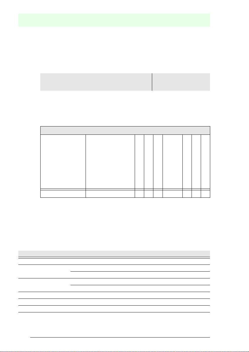
General
AS-i 3.0 EtherNet/IP Gateway, 2 Master with duplicate
VBG-EN-K30-DMD-S16
address' recognition and AS-i inspector, integrated
Safety Monitor (16 release circuits)
Tab. 2-1.
The AS-i/Gateway with integrated Safety Monitor combines two devices in one
housing: an
AS-i 3.0 EtherNet/IP Gateway and a Safety Monitor for 2 AS-i circuits.
The safety unit provides 4 inputs which can be defined as either EDM or as
START inputs.
Functions of the device
–
2 master
Relais circuits
AS-i
Master, power supply
Diagnostic interface
Semiconductor outputs
SaW outputs
VBG-EN-K30-DMD-S16 16 2 2 RS 232 2 16 2
Tab. 2-2.
The EtherNet/IP Gateway serves to connect AS-i systems to the superordinate
EtherNet/IP controller.
All possibilities offered by AS-i can be used via EtherNet/IP.
Commissioning, debugging and setting up of the AS-i parameters can be accom-
plished with the use of push-buttons, the display and the LEDs, but it can also be
handled via Ethernet TCP/IP or via the diagnostic interface.
Safety relays
Caption
2 master: The device is a double master
Relais circuits: number of release circuits
16: safety unit generates 16 independent switching signals
AS-i: number of AS-i circuits
2: safety unit functions with two equal AS-i circuits
Master, power supply: 2: The unit contains two AS-i Masters.
Diagnostic interface: type of the diagnostic port
Semiconductor outputs: number of semiconductor outputs
Subject to reasonable mod ifications due to technical advances. © Pepperl+Fuchs, Printe d in Germany
10
Pepperl+Fuchs Group · Tel.: Germany (6 21) 7 76-0 · USA (3 30) 4 25 35 55 · Singapore 7 79 90 91 Internet http://www.pepperl-fuchs.com
Tab. 2-3.
Issue date: 17.4.2009
Page 11
Caption
SaW outputs: number of SaW outputs
Safety relays: number of safety relays
2.2 Brief description
The actuator-sensor interface (AS-i) has established itself as a system for networking primarily binary sensors and actuators at the lowest level of the automation hierarchy. The high number of installed systems, the ease of use and the reliable operating behaviour also make the AS-i interesting in the area of machine
safety.
The safety AS-i system is intended for safety applications up to Category 4/
SIL 3. Mixed operation of standard components and safe components is possible.
The AS-i/Gateways with integrated Safety Monitor monitors within an AS-i system
the safe slaves which have been assigned according to the configuration specified by the user with the configuration software. In the event of a stop request or a
defect, the AS-i/Gateways with integrated Safety Monitor switches off the system
in protective operation mode with a maximum reaction time of 40 ms.
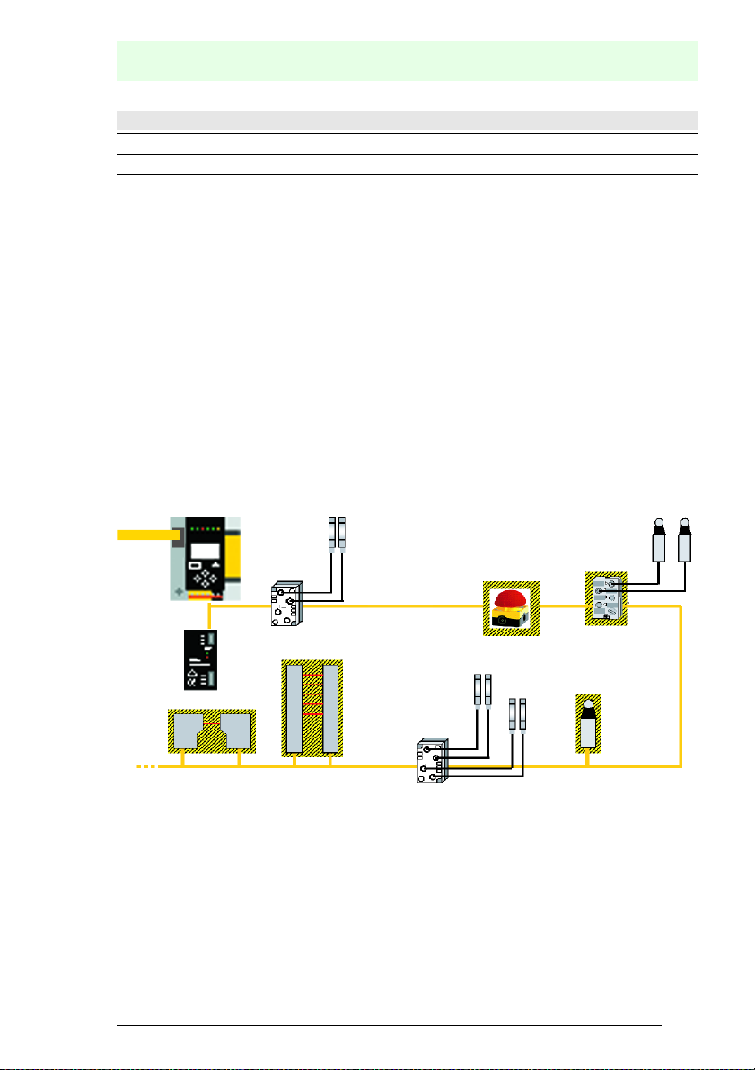
AS-i/Gateway with integrated Safety Monitor
Standard
module
Safety emergency
shutdown switches
AS-Interface
Safety
module
General
Tab. 2-3.
AS-i power
supply unit
Protective photoelectric
sensor
Fig. 2-1. Safe and standard components in an AS-i network
Protective photoelectric
light barrier
Standard
module
Safety position
switch
Multiple AS-i Safety Monitors can be used within an AS-i system. In this way, a
safe slave can be monitored by multiple AS-i Safety Monitors.
Issue date: 17.4.2009
Subject to reasonable modifications due to technical advances. © Pepperl+Fuchs, Printed in Germany
Pepperl+Fuchs Group · Tel.: Germany (6 21) 7 76-0 · USA (3 30) 4 25 35 55 · Singapore 7 79 90 91 Internet http://www.pepperl-fuchs.com
11
Page 12

AS-i 3.0 EtherNet/IP Gateway with integrated Safety Monitor
3. Safety
3.1 Safety standard
The AS-I Safety Monitor has been developed, manufactured, tested and submitted for type testing in accordance with the safety standards prevailing at the time
of testing. The safety requirements per Category 4 in accordance with EN 954-1,
SIL3 in accordance with EN 61 508 and Performance Level “e” in accordance
with EN ISO 13 849-1 are met by all devices.
Information!
A detailed listing of the values for probability of failure (PFD values) can be found in
section <Safety-relevant characteristic data>.
Following a risk analysis you can sue the AS-I Safety Monitor in accordance with
its safety category as a shut-down protection device for protecting hazardous areas.
3.2 Intended use
3.2.1 Conditions of use
The AS-I Safety Monitor has been developed as a shut-down protection device
for protecting hazardous areas on powered equipment.
Attention!
Protection of operating personnel and equipment is not provided is the device is
not used in accordance with its intended use.
Safety
Attention!
Manipulation of and changes to the devices other than expressly described in this
Manual are not permitted.
3.2.2 Residual risks (EN 292-1)
The circuits suggested in this Manual have been tested and verified with the
greatest care. The prevailing standards and regulations are met when using the
components and wiring shown. Residual risks remain if:
• There are any deviations from the suggested wiring concept which may result
in the connected safety-relevant assemblies or protective devices not being
incorporated or only insufficiently incorporated into the safety circuit.
• The operator does not follow the prevailing safety regulations for operation,
setting and maintenance of the machine. Machine inspection and maintenance intervals must be strictly observed.
3.3 Areas of application
The AS-I Safety Monitor, when properly used, enables the operation of sensorcontrolled personal protection equipment and additional safety components.
Subject to reasonable mod ifications due to technical advances. © Pepperl+Fuchs, Printe d in Germany
12
Pepperl+Fuchs Group · Tel.: Germany (6 21) 7 76-0 · USA (3 30) 4 25 35 55 · Singapore 7 79 90 91 Internet http://www.pepperl-fuchs.com
Issue date: 17.4.2009
Page 13

AS-Interface
Safety
The device also assumes the mandatory E-STOP function (Stop Category 0 or 1)
for all non-manually operated machines, dynamic monitoring of the restart function and the protection monitoring function.
Examples for use of the AS-I Safety Monitor:
The device is used economically in machines and equipment in which the standard AS-I bus is the local bus. Using the Safety Monitor as a bus component allows already existing AS-I bus configurations to be easily expanded, and safety
components having the corresponding AS-i Safety at Work interface can be inserted without difficulty. If there is no AS-I Safety at Work interface on the safety
component, so-called coupling modules can be used to establish the connection.
Existing AS-I masters and AS-I power supplies can be used as well.
There are no industry-specific restrictions. Some of the key applications are listed
below:
• Machine tools
• Expanded machining centers with multiple control elements and safety sensors for wood and metal processing
• Printing and paper processing machines, trimming machines
• Packaging machinery, both stand-alone and as systems
• Food and beverage machinery
• Workpiece and bulk material conveying systems
• Rubber and plastics industry processing machinery
• Automatic assembly and handling equipment.
3.4 Organizational requirements
3.4.1 Documentation
All the specifications in this System Manual, in particular the sections “Safety Instructions” and “Commissioning”, must be strictly observed.
All the safety instructions in the manual “ASIMON 3 G2 Configuration Software”
must be strictly observed.
Please note the safety rules when configuring the safety functions, see section
<Configuration of the safety functions>. Checking of the release code and testing
the system must be documented in writing and is part of the system documentation.
Keep this System Manual in a safe location where it can be readily accessed. It
should always be available.
3.4.2 Traceability of the devices
The ordering party is responsible for ensuring traceability of the devices by serial
number!
3.4.3 Safety regulations
Observe the locally prevailing legal regulations and requirements of the trade associations.
Issue date: 17.4.2009
Subject to reasonable modifications due to technical advances. © Pepperl+Fuchs, Printed in Germany
Pepperl+Fuchs Group · Tel.: Germany (6 21) 7 76-0 · USA (3 30) 4 25 35 55 · Singapore 7 79 90 91 Internet http://www.pepperl-fuchs.com
13
Page 14

AS-i 3.0 EtherNet/IP Gateway with integrated Safety Monitor
3.4.4 Qualified personnel
Installation, commissioning and maintenance of the devices are to be performed
only by qualified specialists.
Electrical work is to be performed only by electrical technicians.
Setting and changing the device configuration via PC and ASIMON 3 G2 configu-
ration software are to be performed only by an authorized safety representative.
The password for changing a device configuration must be kept under lock and
key by the safety representative.
3.4.5 Repair
Repairs, in particular opening of the housing, are to be performed only by the
manufacturer or by an authorized representative of the manufacturer.
3.4.6 Disposal
Information!
Electronic waste is hazardous waste. Please comply with all local ordinances when
disposing this product!
The device does not contain batteries that need to be removed before disposing it.
Safety
Subject to reasonable mod ifications due to technical advances. © Pepperl+Fuchs, Printe d in Germany
14
Pepperl+Fuchs Group · Tel.: Germany (6 21) 7 76-0 · USA (3 30) 4 25 35 55 · Singapore 7 79 90 91 Internet http://www.pepperl-fuchs.com
Issue date: 17.4.2009
Page 15
4. Spezifications
4.1 Technical data
Attention!
The AS-I power supply for the AS-I components must have isolation per IEC 60
742 and be able to handle momentary power interruptions of up to 20 ms. The
power supply for the 24 V supply must also have isolation per IEC 60 742 and be
able to handle momentary power interruptions of up to 20 ms. The maximum output voltage of the power supply must also be less than 42 V in case of a fault.
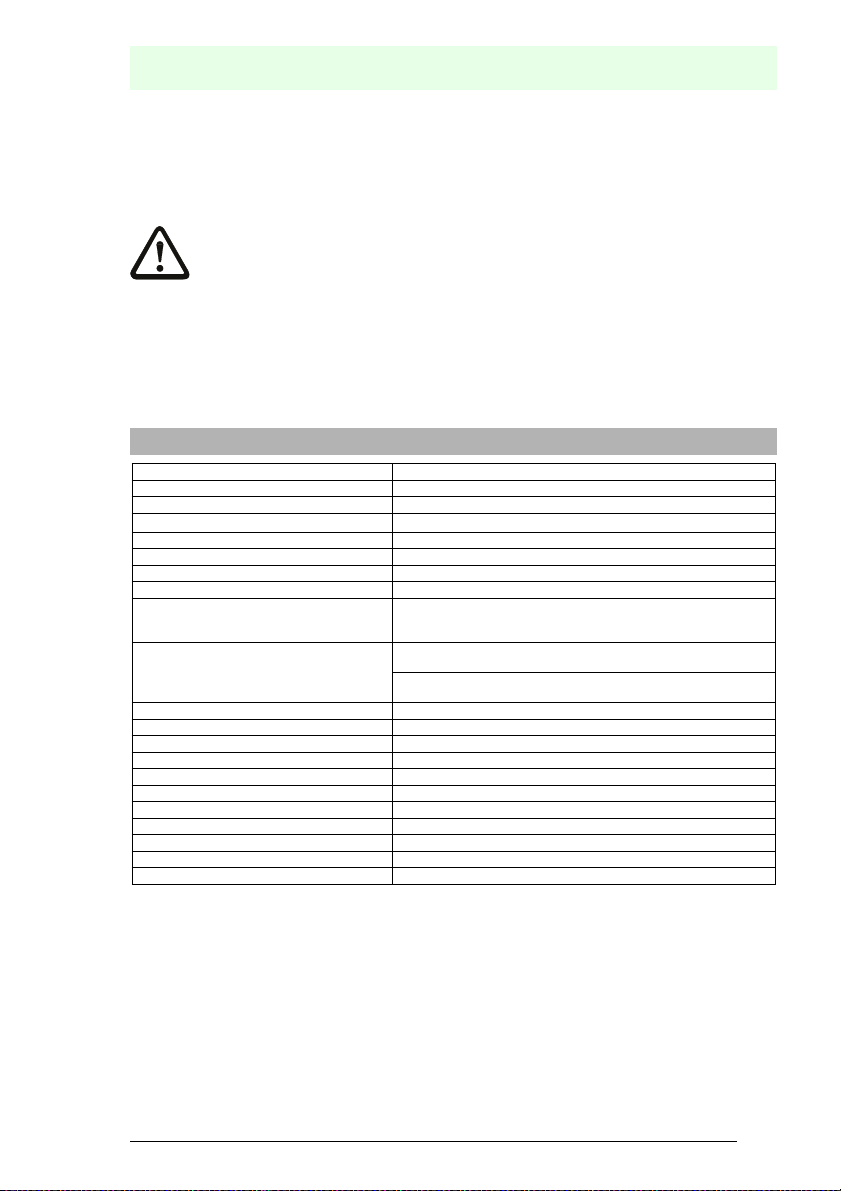
4.1.1 Data sheet VBG-EN-K30-DMD-S16
VBG-EN-K30-DMD-S16
Ethernet/IP interface RJ-45
Baud rates 10/100 MBaud
Serial interface RS 232
AS-i cycle time 150 Ps
Safety monitor
Release circuit 4-cha nnel
Start delay < 10 s
Respond delay < 40 ms
Inputs:
4 x EDM/Start
Output:
4 x output switching elements
Card slot chip card for storage of configuration data
Displays
LCD indication of slave addresses and error messages
LED power power on
LED net Ethernet/IP master recognized
LED config error configuration error
LED U AS-i AS-i voltage OK
LED AS-i active AS-i normal operation active
LED prg enable automatic addresses programming enabled
LED prj mode configuration mode active
LED AUX auxiliary power
(number of slaves + 2)
*
EDM: inputs of external device monitoring circuits
start: start inputs
switching current statical 4 mA at 24 V, dynamic 30 mA at 24 V (T=100 µs)
relay outputs (output circuits 1 and 2)
max. contact load: 3 A AC-15 at 30 V, 3 A DC-13 at 30 V
semiconductor outputs (output circuits 3 and 4)
max. contact load: 0,5 A DC-13 at 30 V
AS-Interface
Spezifications
Issue date: 17.4.2009
Subject to reasonable modifications due to technical advances. © Pepperl+Fuchs, Printed in Germany
Pepperl+Fuchs Group · Tel.: Germany (6 21) 7 76-0 · USA (3 30) 4 25 35 55 · Singapore 7 79 90 91 Internet http://www.pepperl-fuchs.com
15
Page 16
AS-i 3.0 EtherNet/IP Gateway with integrated Safety Monitor
Spezifications
VBG-EN-K30-DMD-S16
4 x LED EDM/Start state of input of ext. device monitoring circuit
4 x LED output circuit state of output circuit
Electrical data
Operating current master power supply, approx. 300 mA out of AS-i network 1,
Operating voltage AS-i voltage 30 V DC
Voltage of insulation t 500 V
Standards EN 61 000-6-2, EN 61 000-6-4
Housing AS-i master housing in stainless steel
Ambient operating temperature 0°C … +55°C
Storage temperature -25°C … +85°C
Dimensions (L / W / H in mm) 120 / 100 / 96
Protection category IEC 60 529 IP20
Tolerable loading referring to impacts and vibrations according to EN 61 131-2
Weight 800 g
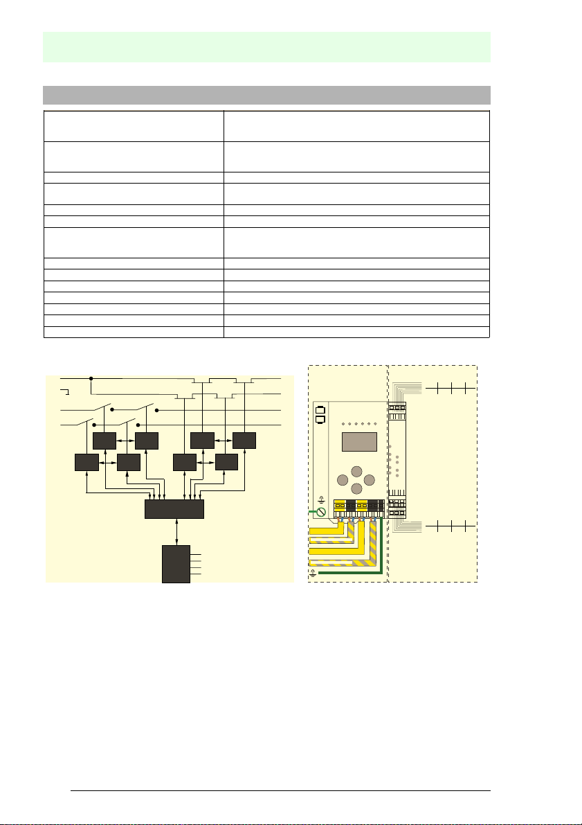
Safety Monitor block diagram: Connections: Gateway + Safety Monitor
LED off: open
LED on: closed
LED off: open
LED on: closed
approx. 70 mA out of AS-i network 2
EN 62 061, SIL3, IEC 61 508, SIL3
EN 13 849, performance level e
24 V
0 V
1.13 1.14
2.13
16
Freigabe
(Release)
Freigabe
(Release)
Subject to reasonable mod ifications due to technical advances. © Pepperl+Fuchs, Printe d in Germany
Pepperl+Fuchs Group · Tel.: Germany (6 21) 7 76-0 · USA (3 30) 4 25 35 55 · Singapore 7 79 90 91 Internet http://www.pepperl-fuchs.com
Freigabe
(Release)
Freigabe
(Release)
Freigabe
(Release)
Sicherheitsmonitor
(Safety Monitor)
Eingänge
(Inputs)
Freigabe
(Release)
Freigabe
(Release)
Freigabe
(Release)
1.Y1 (EDM 1 / Start 1)
2.Y1 (EDM 2 / Start 2)
1.Y2 (EDM 3 / Start 3)
2.Y2 (EDM 4 / Start 4)
3.14
4.14
2.14
Ethernet/IP
+ASI 1–
ASI 1 +PWR- (max. 8A)
+ ASI 2 –
ASI 2 +PWR- (max. 8A)
+
+-+-+
output switching elements
-
-
+
output switching elements
1.13
0 V
+
2.Y2
2.Y1
EDM/START inputs
1.Y1
+
+
4.14
1.14
3.14
EDM/START inputs
2.13+24 V
1.Y2
2.14
Issue date: 17.4.2009
Page 17
AS-Interface
Spezifications
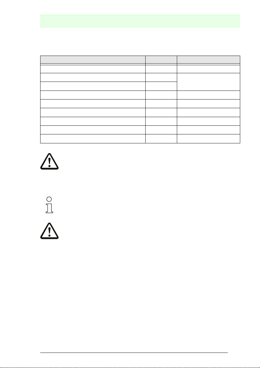
4.2 Safety-relevant characteristic data
Characteristic data Value Standard
Safety category 4 EN 954-1
Safety category 4 EN 13849-1:2006/PLe Cat 4
Performance Level (PL) e
Safety Integrated Level (SIL) 3 IEC 61508
Lifespan (TM) in years 20 EN 13849-1:2006/PLe Cat 4
Maximum switch-on time in months 12 IEC 61508
PFD
PFH
(probability of a dangerous failure per hour) < 5,36 x 10
D
Max. system reaction time in milliseconds
< 9,25 x 10
40 IEC 61508
-6
IEC 61508, EN 62061
-9
IEC 61508, EN 62061
Tab. 4-4.
Attention!
In addition to the system reaction time of max. 40 ms, the reaction times of the safe ASinterface sensor slave, of the sensor being used for monitoring, of the safe AS-interface
actuator slave and of the actuator used for this purpose must still be added. Please note
that additional reaction times may likewise arise through the configuration of the safety
monitor.
Notice!
Refer to the technical data for the slaves as well as to that for the sensors and actuators
for the reaction times to be added.
Attention!
The system reaction times of the daisy-chained AS-interface components are added up.
Issue date: 17.4.2009
Subject to reasonable modifications due to technical advances. © Pepperl+Fuchs, Printed in Germany
Pepperl+Fuchs Group · Tel.: Germany (6 21) 7 76-0 · USA (3 30) 4 25 35 55 · Singapore 7 79 90 91 Internet http://www.pepperl-fuchs.com
17
Page 18
AS-i 3.0 EtherNet/IP Gateway with integrated Safety Monitor
4.3 System reaction times – example calculations
System components:
AS-i network 1
ASI1
AS-i network 2
ASI2
Safe sensor slave (EMERGENCY-OFF switch: t
S1-1
Safe sensor slave (safety light barrier: t
S1-2
Safe sensor slave (EMERGENCY-OFF switch: t
S2-1
Safe actuator slave (motor starter: t
A2-1
SM1-1 Safety monitor with 16 relais circuits and one safe AS-i output in AS-i
network 1
SM1-2 Safety monitor with 2 relais circuits and one safe AS-i output in AS-i
network 1
SM2-1
Safety monitor with 16 relais circuits and one safe AS-i output in AS-i
network 2
RA2-1
= 18 ms)
RS1-2
= 50ms)
Spezifications
= 100 ms)
RS1-1
= 100ms)
RS2-1
Tab. 4-5.
Subject to reasonable mod ifications due to technical advances. © Pepperl+Fuchs, Printe d in Germany
18
Pepperl+Fuchs Group · Tel.: Germany (6 21) 7 76-0 · USA (3 30) 4 25 35 55 · Singapore 7 79 90 91 Internet http://www.pepperl-fuchs.com
Issue date: 17.4.2009
Page 19
AS-Interface
Spezifications
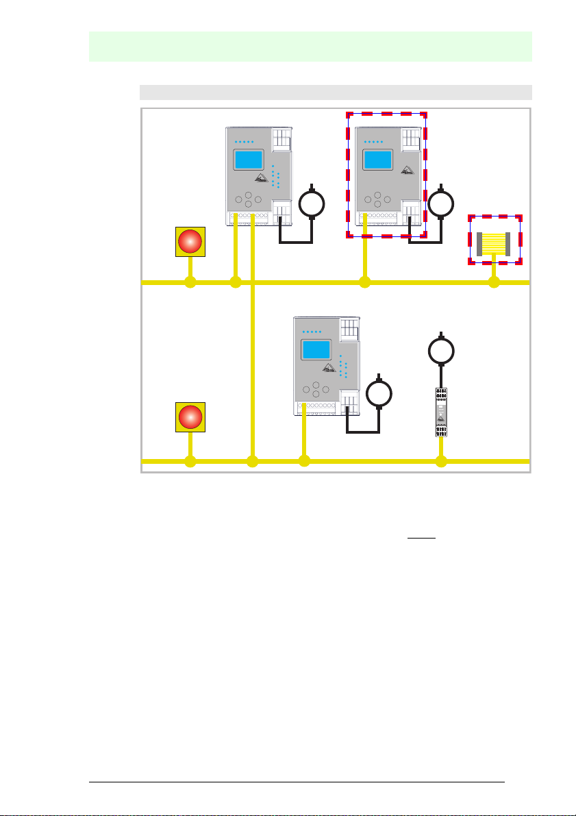
System configuration - example 1: Calculation of the system reaction time
SM1-1
AS-i Safety Monitor
M
S1-1
SM1-2
AS-i Safety Monitor
M
S1-2
AS-i 1
SM2-1
M
AS-i Safety Monitor
S2-1
M
AS-i 2
Upon activation of safety light barrier S1-2, the relay safety output of safety monitor SM1-2 is controlled.
Calculation of the AS-i relevant system reaction time:
t
System total a)
= t
R S1-2
+ t
= 18ms + 40ms = 58ms
R System
I–
I1
Run
Prg
1.13
ASI+
I+
I+
I+
I2
1.Y1
1.Y2
Prg
1
I
I2
1.Y2
1.Y1
Alarm
Pwr
Fault
Out
1.14
1.23
1.24
ASI–
nc
nc
A2-1
Issue date: 17.4.2009
Subject to reasonable modifications due to technical advances. © Pepperl+Fuchs, Printed in Germany
Pepperl+Fuchs Group · Tel.: Germany (6 21) 7 76-0 · USA (3 30) 4 25 35 55 · Singapore 7 79 90 91 Internet http://www.pepperl-fuchs.com
19
Page 20
AS-i 3.0 EtherNet/IP Gateway with integrated Safety Monitor
Spezifications
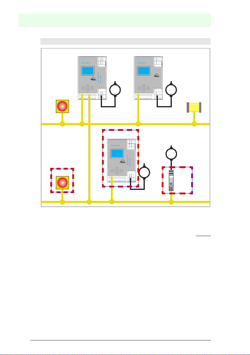
System configuration - example 2: Calculation of the system reaction time
SM1-1
AS-i Safety Monitor
M
S1-1
SM1-2
AS-i Safety Monitor
M
S1-2
AS-i 1
SM2-1
M
AS-i Safety Monitor
S2-1
M
AS-i 2
Upon locking of the EMERGENCY-OFF switch S2-1, the motor starter is controlled via the safe AS-interface output of safety monitor SM2-1.
Calculation of the AS-interface-relevant system reaction time:
t
System total b)
= t
R S2-1
+ t
R System
+ t
= 100ms + 40ms + 50ms = 190ms
R A2-1
I+
I–
I2
I1
Run
1
I
Pwr
Prg
1.14
1.13
ASI–
ASI+
I+
I+
1.Y2
1.Y1
Prg
I2
1.Y2
1.Y1
Alarm
Fault
Out
1.24
1.23
nc
nc
A2-1
Subject to reasonable mod ifications due to technical advances. © Pepperl+Fuchs, Printe d in Germany
20
Pepperl+Fuchs Group · Tel.: Germany (6 21) 7 76-0 · USA (3 30) 4 25 35 55 · Singapore 7 79 90 91 Internet http://www.pepperl-fuchs.com
Issue date: 17.4.2009
Page 21
AS-Interface
Spezifications
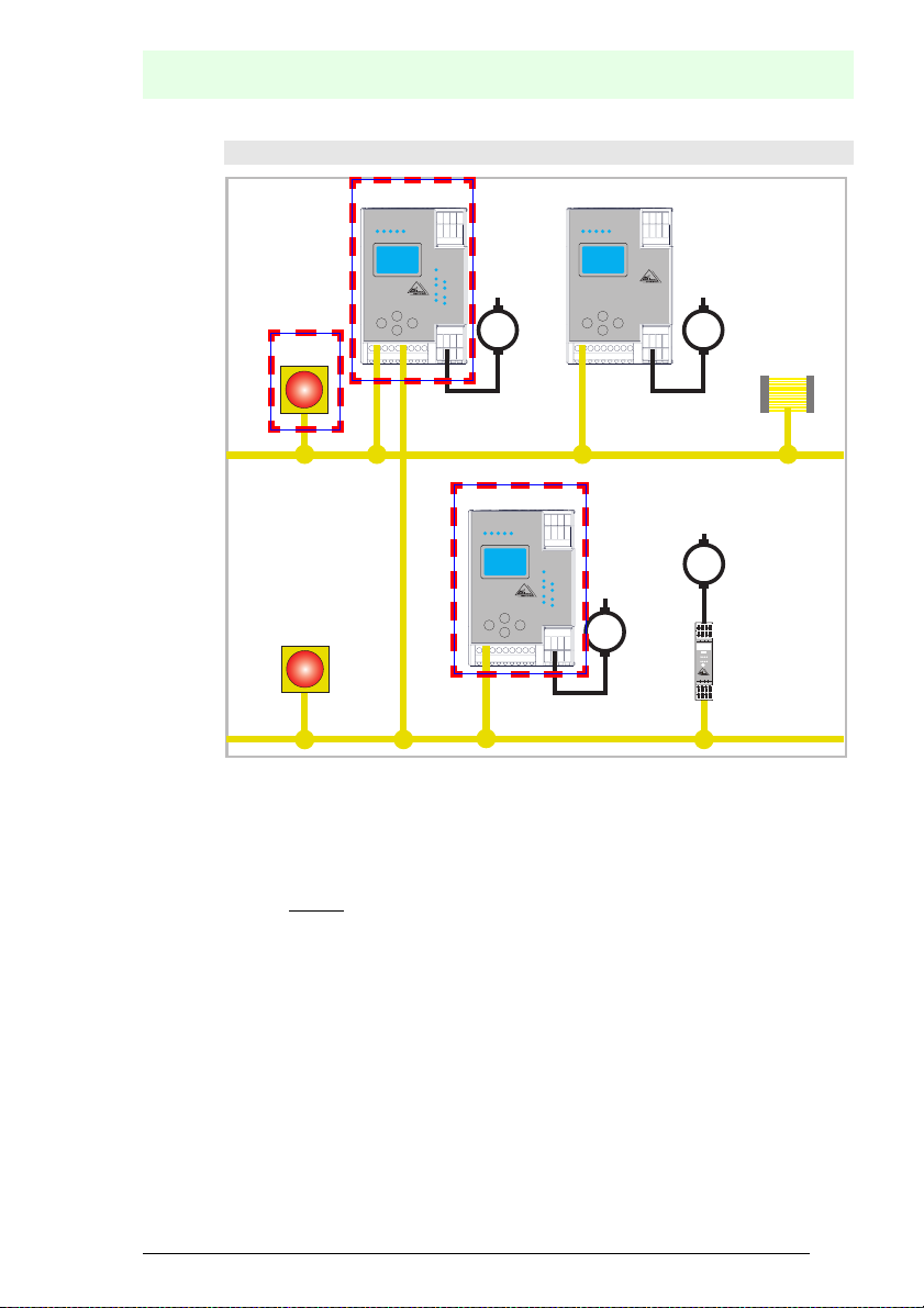
System configuration - example 3: Calculation of the system reaction time
SM1-1
AS-i Safety Monitor
M
S1-1
SM1-2
AS-i Safety Monitor
M
S1-2
AS-i 1
SM2-1
M
AS-i Safety Monitor
S2-1
M
AS-i 2
Upon locking of the EMERGENCY-OFF switch S1-1, the relay output of safety
monitor SM2-1 is controlled via the coupling of the safe AS-interface output of
safety monitor SM1-1.
Calculation of the AS-i relevant system reaction time:
t
System total c)
= t
R S1-1
+ t
R System ASI1
+ t
R System ASI2
40ms = 180ms
I–
I+
I+
I+
I1
I2
1.Y1
1.Y2
A2-1
Run
Prg
1
I
I2
1.Y2
1.Y1
Alarm
Pwr
Fault
Out
Prg
1.13
1.14
1.23
1.24
ASI+
ASI–
nc
nc
= 100ms + 40ms +
4.4 Scope of delivery
The basic unit consists of:
AS-i 3.0 EtherNet/IP Gateway with integrated Safety Monitor.
The following accessories are available:
Software CD with
®
• ASIMON 3 G2 communication software for Microsoft
2000/XP/Vista
®
Windows Me/NT/
• System manual in PDF format (Adobe® Acrobat Reader® Version 5.x or
newer is required for viewing the files)
Issue date: 17.4.2009
Subject to reasonable modifications due to technical advances. © Pepperl+Fuchs, Printed in Germany
Pepperl+Fuchs Group · Tel.: Germany (6 21) 7 76-0 · USA (3 30) 4 25 35 55 · Singapore 7 79 90 91 Internet http://www.pepperl-fuchs.com
21
Page 22
5. Installation
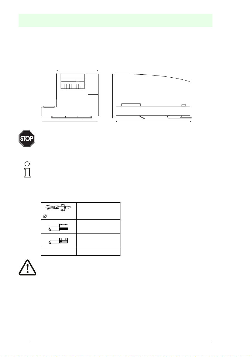
5.1 Dimensions
AS-i 3.0 EtherNet/IP Gateway with integrated Safety Monitor
Installation
78
96
Warning!
Cover the top of the gateway when doing any drilling work above the unit. No particles,
especially metal chips, should be allowed to enter the housing, since this could cause a
short circuit.
Information!
Please refer to installation instruction for this device for detailed mounting information.
5.2 Connections
5 ... 6 mm / PZ2
10
10
AWG 2 x 24 ...12
Attention!
The AS-I power supply for the AS-I components must have isolation per IEC 60 742
and be able to handle momentary power interruptions of up to 20 ms. The power supply for the 24 V supply must also have isolation per IEC 60 742 and be able to handle
momentary power interruptions of up to 20 ms. The maximum output voltage of the
power supply must also be less than 42 V in case of a fault.
110
2 x (0,5 .... 1,5) mm
2 x (0,5 ..
0,8 Nm
7 LB.IN
.. 1,5) mm
120
2
2
Subject to reasonable mod ifications due to technical advances. © Pepperl+Fuchs, Printe d in Germany
22
Pepperl+Fuchs Group · Tel.: Germany (6 21) 7 76-0 · USA (3 30) 4 25 35 55 · Singapore 7 79 90 91 Internet http://www.pepperl-fuchs.com
Issue date: 17.4.2009
Page 23
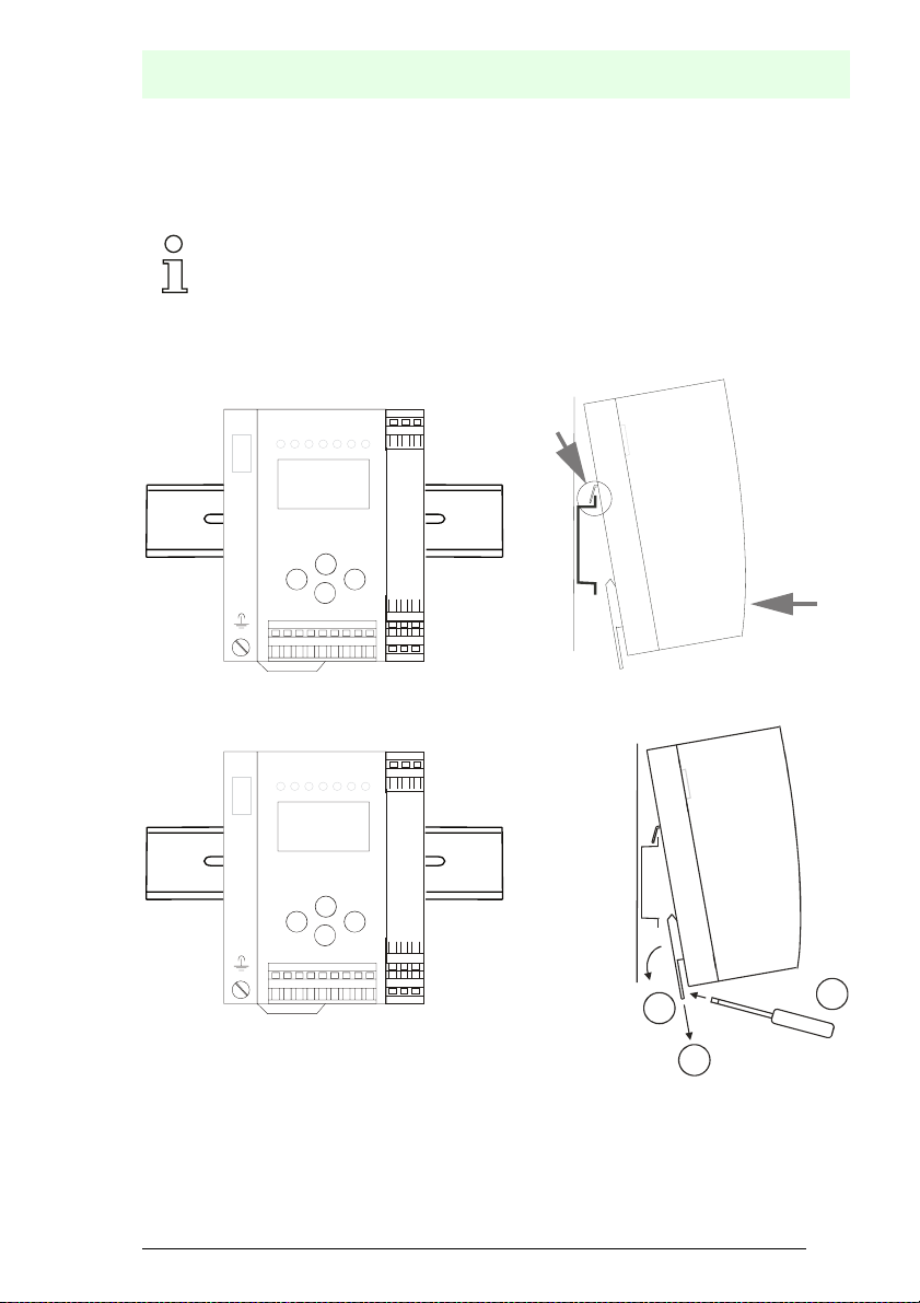
5.3 Installing in the control cabinet
The AS-I/Gateway is installed in the control cabinet on 35mm DIN rails per DIN
EN 50 022.
Information!
The enclosure of the AS-I/Gateway is made of stainless steel. The unit is also suitable for exposed wall mounting.
To install, place the unit on the upper edge of the DIN rail and then snap in the
lower edge.
-
-
+-+
+
AS-Interface
Installation
[1]
[2]
5.4 Removing
-
-
+-+
+
3
2
To remove, press the holding clamps [2] down using a screwdriver [1], press the
unit firmly against the upper rail guide and lift out.
Issue date: 17.4.2009
Subject to reasonable modifications due to technical advances. © Pepperl+Fuchs, Printed in Germany
Pepperl+Fuchs Group · Tel.: Germany (6 21) 7 76-0 · USA (3 30) 4 25 35 55 · Singapore 7 79 90 91 Internet http://www.pepperl-fuchs.com
1
23
Page 24

AS-i 3.0 EtherNet/IP Gateway with integrated Safety Monitor
5.5 Electrical Connection
Information!
Electrical connections are described in section <Electrical connection>.
Information!
See also section <Operation in advanced display mode> for further information.
Installation
Subject to reasonable mod ifications due to technical advances. © Pepperl+Fuchs, Printe d in Germany
24
Pepperl+Fuchs Group · Tel.: Germany (6 21) 7 76-0 · USA (3 30) 4 25 35 55 · Singapore 7 79 90 91 Internet http://www.pepperl-fuchs.com
Issue date: 17.4.2009
Page 25
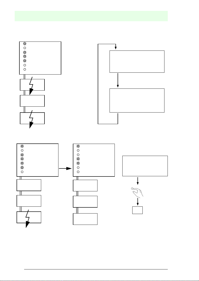
5.6 Commissioning
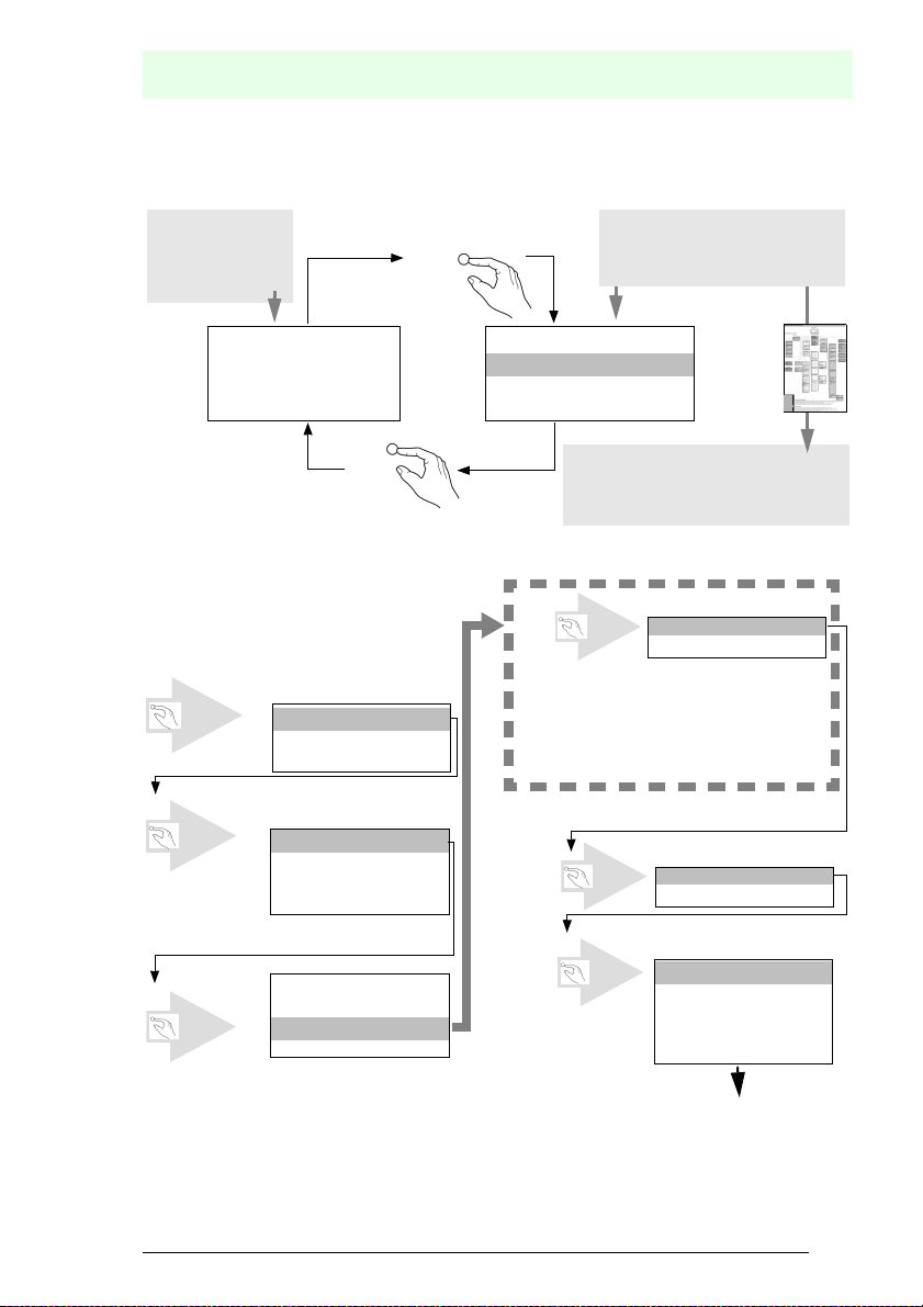
5.6.1
classical display
Switching to advanced display mode
AS-Interface
Installation
advanced display mode
OK
LCD
1.12A
UNKNOWN SLAVE
ESC
5.6.2 Setting of ethernet properties
LCD
OK
OK
TCP/IP OBJECT
ETHERNET OBJECT
IF STATUS
IF CAPABILITY
IF CONTROL
...
IF STATUS
IF CAPABILITY
IF CONTROL
...
ETHERNET/IP
QUICK SETUP
SETUP
DIAGNOSIS
menu structure see additional page
OK
When using DHCP, no adjustment is necessary
OK
1xESC
LCD
USE DHCP
USE STORED VAL.
IF STATUS
IF CAPABILITY
IF CONTROL
PATH TO LINK OBJ .
TCP/IP CONFIG
Issue date: 17.4.2009
Subject to reasonable modifications due to technical advances. © Pepperl+Fuchs, Printed in Germany
Pepperl+Fuchs Group · Tel.: Germany (6 21) 7 76-0 · USA (3 30) 4 25 35 55 · Singapore 7 79 90 91 Internet http://www.pepperl-fuchs.com
25
Page 26
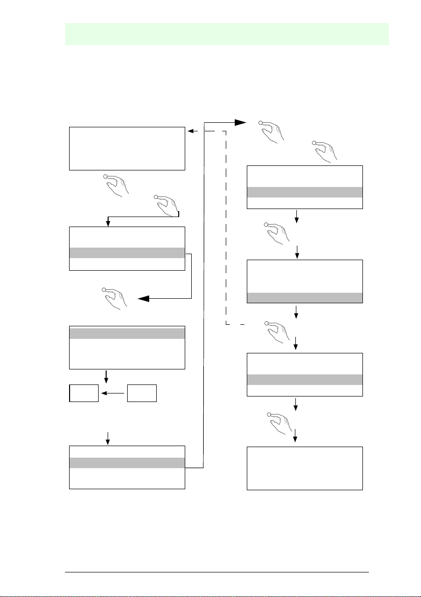
AS-i 3.0 EtherNet/IP Gateway with integrated Safety Monitor
5
S
5
e
U
R
Installation
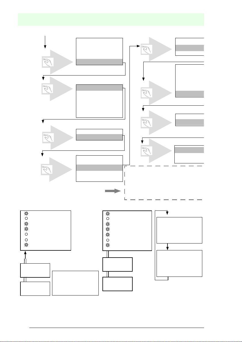
IF STATUS
IF CAPABILITY
IF CONTROL
PATH TO LINK OBJ.
TCP/IP CONFIG
IP ADDRESS
192. 168. 42. 149
NET MASK
255. 255. 255. 0
GATEWAY
0 . 0 . 0
IP ADDRESS
192.168.42.149
↓
OK
OK
(
ESC
5.6.3 Connecting AS-i Slaves
power
net
config error
U AS-i
AS-i active
prg enable
prj mode
AS-i
...
NET MASK
255. 255. 255. 0
GATEWAY
0 . 0 . 0
AS-i Master
AS-i
OK
(
ESC
OK
(
2xESC
Restart the gateway to assume your chang
power
net
config error
U AS-i
AS-i active
prg enable
prj mode
AS-i Master
1. 1
0.5s
NET MASK
255. 255. 25
IP ADDRES
192.168.42.1
NET MASK
255. 255. 25
GATEWAY
0 . 0 . 0
GATEWAY
0 . 0 . 0 . 0
ETHERNET/I
QUICK SET
SLAVE ADD
LCD
AS-i
AS-i
Slave 1
AS-i
Slave 5
Subject to reasonable mod ifications due to technical advances. © Pepperl+Fuchs, Printe d in Germany
26
Pepperl+Fuchs Group · Tel.: Germany (6 21) 7 76-0 · USA (3 30) 4 25 35 55 · Singapore 7 79 90 91 Internet http://www.pepperl-fuchs.com
1. 41
SEARCHING SLAVES
LCD
Slave 1
AS-i
Slave 5
1. 5
0.5s
Issue date: 17.4.2009
Page 27
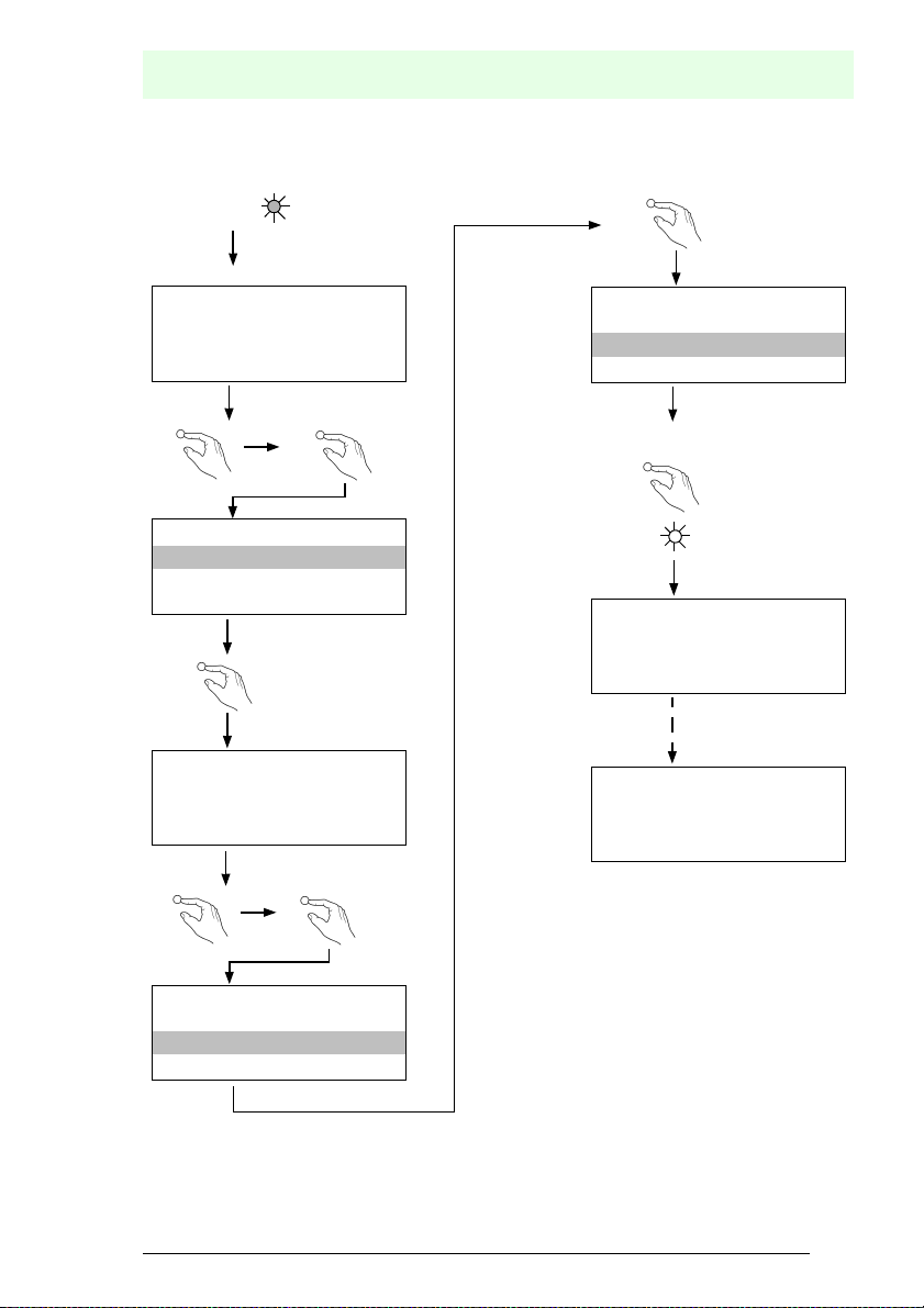
5.7 Quick setup
AS-Interface
Installation
config error
1. 5
1xOK
ETHERNET
QUICK SETUP
SETUP
IO + PARAM. TEST
OK
WARNING:
OUTPUTS MAY BE
RESET
OK
LCD
STORE AS-I
CONFIGURATION
OK
STORE +PRJ MODE
↓
2x ESC
LCD
LCD
LCD
.
CONFIGURATION OK
LCD
HOST ERROR
NO CONNECTION
LCD
OK
↓
LCD
STORE AS-I
CONFIGURATION
STORE +RUN
STORE +PRJ MODE
Issue date: 17.4.2009
Subject to reasonable modifications due to technical advances. © Pepperl+Fuchs, Printed in Germany
Pepperl+Fuchs Group · Tel.: Germany (6 21) 7 76-0 · USA (3 30) 4 25 35 55 · Singapore 7 79 90 91 Internet http://www.pepperl-fuchs.com
27
Page 28
5.8 Error tracing
5.8.1 Faulty slaves
power
net
config error
U AS-i
AS-i active
prg enable
prj mode
AS-i
AS-i 3.0 EtherNet/IP Gateway with integrated Safety Monitor
Installation
1.1
AS-i Master
MISSING SLAVE
LCD
AS-i
Slave 1
AS-i
Slave 5
AS-i
Slave 24
5.8.2 Error display (last error)
power
net
config error
U AS-i
AS-i active
prg enable
prj mode
AS-i
AS-i
Slave 1
AS-i
Slave 5
AS-i
Slave 24
AS-i Master
power
net
Config error
U AS-i
AS-i active
prg enable
prj mode
AS-Interface
AS-i
Slave 1
AS-i
Slave 5
AS-i
Slave 24
2s
1.24
MISSING SLAVE
2s
AS-i Master
set/↓
LCD
LCD
Host error
no connection
1: ON 2: OFF
24
Subject to reasonable mod ifications due to technical advances. © Pepperl+Fuchs, Printe d in Germany
28
Pepperl+Fuchs Group · Tel.: Germany (6 21) 7 76-0 · USA (3 30) 4 25 35 55 · Singapore 7 79 90 91 Internet http://www.pepperl-fuchs.com
Issue date: 17.4.2009
Page 29
5.8.3 Addressing
5.8.3.1 Assigning address 6 to slave currently at address 2
AS-Interface
Installation
LCD
1. 41
SEARCHING SLAVE
OK
2x
↓
ETHERNET
QUICK SETUP
SLAVE ADR TOOL
SLAVE TEST TOOL
OK
LCD
SLAVE ADR TOOL
CONNECT NEW SLAVE
OLD ADDRESS
NEW ADDRESS
Master Slave
Modul anschließen/Connect
module/Raccordez module/
Collegare modulo/Conecte modulo
LCD
SLAVE ADR TOOL
OLD ADDRESS 2
NEW ADDRESS 3
PRG
1x
↓
SLAVE ADR TOOL
OLD ADDRESS 2
NEW ADDRESS 6
PRG
1x
↓
SLAVE ADR TOOL
OLD ADDRESS 2
NEW ADDRESS 6
PRG
OK
SLAVE ADR TOOL
OK
2 x ESC
1. 6
UNKNOWN SLAVE
3 x OK
LCD
LCD
LCD
LCD
Issue date: 17.4.2009
Subject to reasonable modifications due to technical advances. © Pepperl+Fuchs, Printed in Germany
Pepperl+Fuchs Group · Tel.: Germany (6 21) 7 76-0 · USA (3 30) 4 25 35 55 · Singapore 7 79 90 91 Internet http://www.pepperl-fuchs.com
29
Page 30
AS-i 3.0 EtherNet/IP Gateway with integrated Safety Monitor
Installation
For additional information see manual, section <Operation in advanced display
mode>.
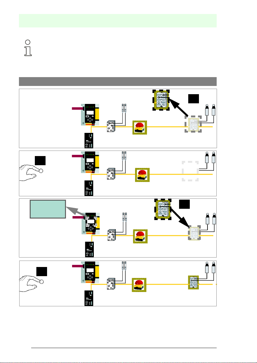
5.8.4 Replacing a defective AS-i Safety Slave
The new slave must be able to send teaching codes and must have the same address as the old one. Only one
missing slave is allowed!
[1]
[2]
ESC/Service
(3 seconds)
CONNECT
NEW SLAVE 17
THEN PRESS
SERVICE
[3]
[4]
ESC/Service
(3 seconds)
Subject to reasonable mod ifications due to technical advances. © Pepperl+Fuchs, Printe d in Germany
30
Pepperl+Fuchs Group · Tel.: Germany (6 21) 7 76-0 · USA (3 30) 4 25 35 55 · Singapore 7 79 90 91 Internet http://www.pepperl-fuchs.com
Issue date: 17.4.2009
Page 31

5.8.5 Replacing the chip card
Always turn off power before inserting or removing the card!
[1]
AS-Interface
Installation
[2]
[3]
[6] [7]
neu/new/neuve/
[8]
[4] [5]
alt/old/ancien/
vecchia/anciano
Issue date: 17.4.2009
Subject to reasonable modifications due to technical advances. © Pepperl+Fuchs, Printed in Germany
Pepperl+Fuchs Group · Tel.: Germany (6 21) 7 76-0 · USA (3 30) 4 25 35 55 · Singapore 7 79 90 91 Internet http://www.pepperl-fuchs.com
31
Page 32

AS-i 3.0 EtherNet/IP Gateway with integrated Safety Monitor
5.8.6 Local parameter setting of safe AS-i/Gateways and Monitors
CHIPCARD AND
DATA
DIFFERENT
CARD->MASTER
MASTER->CARD
CONTINUE
Daten kopieren
Keine Aktion erforderlich
CHIPCARD FOUND
DATA WILL
BE SYNCHRONIZED
Keine Aktion erforderlich
KARTE->MASTER oder
MASTER->KARTE
/No action required/
/Aucune action requise/
/No action required/
/Aucune action requise/
Unsichere Daten / Non-safe data/
Données non-sécurisées/
Dati non sicuri / Datos no seguros/
Geräte+Chipdaten ungleich
(Werkskonfiguration geändert)
/Device+card data not equal
(Factory configuartion changed)
Fehlermeldung:
/Error message/
Geräte+Chipdaten gleich
/Device data+card data equal/
Keine Meldung
Karte leer + formatiert
/Card empty + formatted/
Daten werden synchronisiert:
/No message/
/Data being synchronized/
Installation
Copy data CARD->MASTER
or MASTER->CARD
Copier données Carte->Maître ou
Maître-Carte
Copiare dati Chipcard->Master o
copiare dati Master->Chipcard
Copiar dates Chip->Maestro o
/Nessuna azione richiesta/
/Ninguna deción requrida/
/Nessuna azione richiesta/
/Ninguna deción requrida/
Maestro ->Chip
konfiguration)
DATA FROM
(Werks
Daten kompatibel
/Data compatible (factory
configuration)/
Daten nicht kompatibel
/Data not compatible/
Karte nicht formatiert
/Card not formatted/
Subject to reasonable mod ifications due to technical advances. © Pepperl+Fuchs, Printe d in Germany
32
Pepperl+Fuchs Group · Tel.: Germany (6 21) 7 76-0 · USA (3 30) 4 25 35 55 · Singapore 7 79 90 91 Internet http://www.pepperl-fuchs.com
CHIPCARD TAKEN
Daten werden übernommen:
/Data being acepted/
CHIPCARD NOT
COMPATIBLE
Fehlermeldung:
/Error message/
NEW CHIPCARD
WILL BE FORMATTED
DATA WILL BE
Karte wird formatiert:
SYNCHRONIZED
/Formatting card /
Keine Aktion erforderlich
/No action required/
/Aucune action requise/
/Nessuna azione richiesta/
/Ninguna deción requrida/
Karte löschen
/Clear the card/
/Supprimer carte/
/Cancellare chipcard/
/Borrar chip/
Keine Aktion erforderlich
/No action required/
/Aucune action requise/
/Nessuna azione richiesta/
/Ninguna deción requrida/
Issue date: 17.4.2009
Page 33

Stamm-/Vollständige
Konfiguartion auf der Chipkarte
enthalten
/Master configuration or
complete configuration on the
card
Sichere Daten / Safe data/
Données sécurisées/
Dati sicuri / Datos seguros
Stamm-/Vollständige
Konfiguartion auf der Chipkarte
/Master configuration or
complete configuration on the
Gerät enthält keine validierte
Konfiguration
/No validated configuration in
Gerät enthält validierte
Konfiguration, Daten ungleich
/There is a validated
configuration on the card, data
not equal
card
Gerät enthält validierte
Konfiguration
/There is a validated
configuration on the card
the device/
Stamm-/Vollständige
Konfiguartion auf der Chipkarte
/Master configuration or
complete configuration on the
card
ERROR.
CHIPCARD AND
SAFETY DATA
COPY BANK A TO
MONITOR
...
RELEASE CODE:
DIFFERENT.
1BDF
Beide Konfigurationen ungleich/
Both configurations not equal
Fehlermeldung:
/Error message/
Beide Konfigurationen gleich/
Both configurations identical
Keine Meldung
/No message/
Datenfreigabe per
Release-Code notwendig:
/Data release via release code
required/
DELETE CHIPCARD
OR SAFETY DATA
Daten löschen
/Clear data/
/Supprimer données /
/Cancellare dati
Keine Aktion erforderlich
/No action required/
/Aucune action requise/
---------------
TYPE CODE
1BDF OK
Konfiguration per
Release-Code freigeben
/Validate the configuration
AS-Interface
Installation
/Borrar datos
/Nessuna azione richiesta/
/Ninguna deción requrida/
via release code/
/Respecter les indications
de sécurité exposées dans
le manuel ASIMON
/Osservare le istruzioni di
sicurezza riportate nel
manuale ASIMON
/Habilitar la configuratión
con el código de liberatión/
CHIPCARD FOUND
SAFETY DATA WILL
Validierte Konfiguration im
Gerät, Chipkarte leer
/Validated configuration
in the device, chip card empty/
Keine validierte Konfiguration im
Gerät + Chipkarte
/No validated configuration in
the device + chip card/
Sichere Daten auf der
Chipkarte nicht kompatibel
zum Gerät
/Safe data on the chip card
not compatible to the device/
BE SYNCHRONIZED
Daten werden synchronisiert:
/Data being synchronized/
CHIPCARD FOUND
SAFETY DATA WILL
Daten werden synchronisiert:
/Data being synchronized/
CHIPCARD NOT
COMPATIBLE
Fehlermeldung:
/Error message/
Keine Aktion erforderlich
BE SYNCHRONIZED
Keine Aktion erforderlich
Karte löschen
/No action required/
/Aucune action requise/
/Nessuna azione richiesta/
/Ninguna deción requrida/
/No action required/
/Aucune action requise/
/Nessuna azione richiesta/
/Ninguna deción requrida/
/Clear the card/
/Supprimer carte/
/Cancellare chipcard/
/Borrar chip/
For further information see manual, section <Chip card>
Issue date: 17.4.2009
Subject to reasonable modifications due to technical advances. © Pepperl+Fuchs, Printed in Germany
Pepperl+Fuchs Group · Tel.: Germany (6 21) 7 76-0 · USA (3 30) 4 25 35 55 · Singapore 7 79 90 91 Internet http://www.pepperl-fuchs.com
33
Page 34

AS-i 3.0 EtherNet/IP Gateway with integrated Safety Monitor
Installation
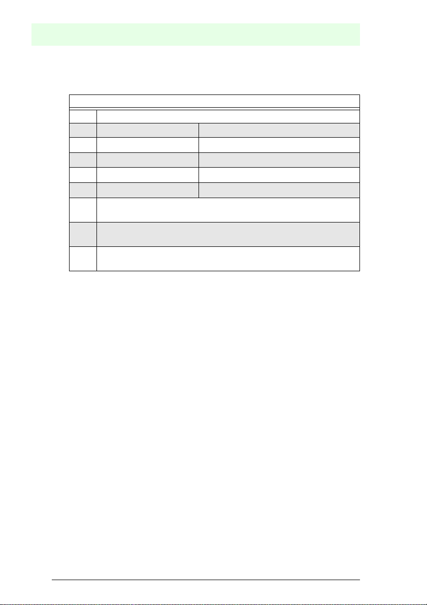
5.9 Safe configuration using ASIMON 3 G2
ASIMON 3 G2
Software
Start
Before commissioning the safety unit, put the gateway into operation!
ASIMON 3 G2 Software
Change the preset password during the first use of the device (Monitor/change password)!
ASIMON 3 G2 Software
Create the desired configuration.
ASIMON 3 G2 Software
Download the configuration with MONITOR / PC-> MONITOR into the device. Enter the password for
this purpose.
ASIMON 3 G2 Software
You can acknowledge the request TEACH CODE SEQUENCES? selecting "Yes", or you can do it later
via display selecting "No".
ASIMON 3 G2 Software
Check the configuration log (respect instructions in <chap. 5.8> of the ASIMON manual!).
ASIMON 3 G2 Software
Validate the configuration with MONITOR –> VALIDATION.
ASIMON 3 G2 Software
Start the monitor with MONITOR–> START.
Subject to reasonable mod ifications due to technical advances. © Pepperl+Fuchs, Printe d in Germany
34
Pepperl+Fuchs Group · Tel.: Germany (6 21) 7 76-0 · USA (3 30) 4 25 35 55 · Singapore 7 79 90 91 Internet http://www.pepperl-fuchs.com
Issue date: 17.4.2009
Page 35

ASIMON 3 G2 Software
☺Press OK for Menu
Output Circuit
1:ON 2:OFF
If you have assigned the safety monitor its own address in the software
ASIMON 3 G2, adjust the configuration in the AS-i master (Quick Setup)! This is also
valid when using simulated slaves.
Please consider notes on safety in the software manual ASIMON 3 G2!
☺ Press OK for Menu
Output Circuit
1:ON 2:ON
3:ON 4:ON
The device is in the protected mode now.
AS-Interface
Installation
Issue date: 17.4.2009
Subject to reasonable modifications due to technical advances. © Pepperl+Fuchs, Printed in Germany
Pepperl+Fuchs Group · Tel.: Germany (6 21) 7 76-0 · USA (3 30) 4 25 35 55 · Singapore 7 79 90 91 Internet http://www.pepperl-fuchs.com
35
Page 36

AS-i 3.0 EtherNet/IP Gateway with integrated Safety Monitor
6. Maintenance
6.1 Checking for safe turn-off
The safety representative is responsible for checking flawless function of the AS-i
Safety Monitor within the safety system.
Safe turn-off when an associated safe sensor or switch is triggered must be
checked at least once a year.
Attention!
To do this, actuate each safe AS-i slave and observe the switching behavior of
the output circuits of the AS-i Safety Monitor.
Attention!
Note the maximum turn-on duration and the overall turn-on operating duration.
These values depend on the PFD value selected (see section <Safety-relevant
characteristic data>).
When the maximum turn-on duration is reached (three, six or twelve months),
check the complete safety system and its proper function.
When the total operating time (20 years) has been reached, the device must be
returned to the manufacturer to check for proper function.
Maintenance
Subject to reasonable mod ifications due to technical advances. © Pepperl+Fuchs, Printe d in Germany
36
Pepperl+Fuchs Group · Tel.: Germany (6 21) 7 76-0 · USA (3 30) 4 25 35 55 · Singapore 7 79 90 91 Internet http://www.pepperl-fuchs.com
Issue date: 17.4.2009
Page 37

7. Electrical connection
7.1 Overview of terminals, indicators and operating elements
7.1.1 VBG-EN-K30-DMD-S16
AS-Interface
Electrical connection
[1]
[6]
[2]
[3]
[1]
[4]
[5]
-
-
+-+
+
[6]
[7]
[8]
Legend:
[1] LEDs
[2] EtherNet/IP interface
[3] LC display
[4] Buttons
[5] Terminals: Supply voltage and AS-i circuit
[6] Terminals: Safety monitor
[7] Chip card slot
[8] RS 232 diagnostics port
1
5 ... 6 mm / PZ2
10
2 x (0,5 .... 1,5) mm
10
2 x (0,5 ..
AWG 2 x 24 ...12
0,8 Nm
7 LB.IN
.. 1,5) mm
2
2
Issue date: 17.4.2009
Subject to reasonable modifications due to technical advances. © Pepperl+Fuchs, Printed in Germany
Pepperl+Fuchs Group · Tel.: Germany (6 21) 7 76-0 · USA (3 30) 4 25 35 55 · Singapore 7 79 90 91 Internet http://www.pepperl-fuchs.com
1. Only together with ASIMON 3 G2 Software or AS-i Control Tools
37
Page 38

AS-i 3.0 EtherNet/IP Gateway with integrated Safety Monitor
7.2 AS-i bus connection
Blue
AS-i-
Brown
AS-i+
Blau
AS-i-
Electrical connection
Braun
AS-i+
Yellow ASi ribbon cable
2-conductor AS-i round cable
(Recommended: flexible power cable
H05VV-F2x1,5 per DIN VDE 0281)
Information!
Electrical work is to be performed only by electrical technicians.
7.3 Information about the device types
Information!
A listing of the individual devices and their features can be found in section <Product
information>.
7.4 AS-i and power supply terminal assignments
Information!
The cable indicated by hatching must not have slaves or repeaters connected to
it.
The yellow cable must not have AS-i power suppliers or additional masters connected to it.
Information!
The function ground can be connected either to the grounding screw or to the terminal.
The function ground should be made with as short a cable as possible to ensure good
EMC characteristics.
Therefore function grounding using the grounding screw is preferred.
Attention!
The AS-I power supply for the AS-I components must have isolation per IEC 60
742 and be able to handle momentary power interruptions of up to 20 ms. The
power supply for the 24 V supply must also have isolation per IEC 60 742 and be
able to handle momentary power interruptions of up to 20 ms. The maximum output voltage of the power supply must also be less than 42 V in case of a fault.
Subject to reasonable mod ifications due to technical advances. © Pepperl+Fuchs, Printe d in Germany
38
Pepperl+Fuchs Group · Tel.: Germany (6 21) 7 76-0 · USA (3 30) 4 25 35 55 · Singapore 7 79 90 91 Internet http://www.pepperl-fuchs.com
Issue date: 17.4.2009
Page 39

7.4.1 Electrical connection VBG-EN-K30-DMD-S16
Gateway Safety Monitor
M4
5 mm max!
Function ground
-
+ASI 1–
ASI 1 +PWR– (max. 8A)
+ASI 2–
+
ASI 2 +PWR– (max. 8A)
-
+-+
+
Terminal Signal / Description
+ASI 1– Connection to AS-i Circuit 1
+ASI 2– Connection to AS-i Circuit 2
ASI 1 +PWR– Supply voltage for AS-i Circuit 1 (max. 8 A)
ASI 2 +PWR– Supply voltage for AS-i Circuit 2 (max. 8 A)
FG Function ground
Information!
AS-i Circuits 1 and 2 are powered by separate power supplies.
AS-Interface
Electrical connection
Information!
For additional information, please refer to the section <AS-i and power supply terminal
assignments>.
Issue date: 17.4.2009
Subject to reasonable modifications due to technical advances. © Pepperl+Fuchs, Printed in Germany
Pepperl+Fuchs Group · Tel.: Germany (6 21) 7 76-0 · USA (3 30) 4 25 35 55 · Singapore 7 79 90 91 Internet http://www.pepperl-fuchs.com
39
Page 40

AS-i 3.0 EtherNet/IP Gateway with integrated Safety Monitor
7.5 Diagnostics interface
The service and diagnostics interface (in conjunction with AS-i Control Tools or
ASIMON 3 G2 software) is used for communication between the PC and the unit.
7.5.1 Diagnostics port RS 232
The service and diagnostics interface is configured as a mini DIN-6 female and it
is placed on the front plate, on the left hand side.
7.6 Chip card
The configuration is stored in a fixed installed EEPROM and can be overwritten
by the chip card. The chip card does not have to be inserted in operation.
Warning!
Power must always be turned off when removing or inserting the chip card!
Electrical connection
7.7 EtherNet/IP interface
A
B
The EtherNet/IP interface consists of two RJ-45 sockets. It is placed on the left
housing side (see section <Overview of terminals, indicators and operating elements>). The RJ-45 socket is based on the MDI (none auto-crossover) and supports 10 Base T or 100 Base TX networks according to the IEEE 802.3
Subject to reasonable mod ifications due to technical advances. © Pepperl+Fuchs, Printe d in Germany
40
Pepperl+Fuchs Group · Tel.: Germany (6 21) 7 76-0 · USA (3 30) 4 25 35 55 · Singapore 7 79 90 91 Internet http://www.pepperl-fuchs.com
Issue date: 17.4.2009
Page 41

7.8 Release circuits
7.8.1 Wiring overview of Safety Monitor
1.13
2.13+24 V
0 V
+
2.Y2
2.Y1
Aux
1.Y1
1.Y2
2.Y1
2.Y2
K1
K2
K3
K4
1.Y2
1.Y1
2.14+4.14+1.14
3.14
1.Y1 (EDM 1/Start 1), 2.Y1 (EDM 2/Start 2), 1.Y2 (EDM 3/Start 3),
2.Y2 (EDM 4/Start 4)
The safety unit provides 4 inputs. The EDM & START inputs can be defined freely.
The inputs may not be connected to other potentials, but rather only directly or
through potential-free switches to + (for EDM/START).
Switching current static 4 mA at 24 V, dynamic 30 mA at 24 V (T=100 µs).
3.14, 4.14
AS-Interface
Electrical connection
Semiconductor outputs. Max. contact load: 0.5 A DC-13 at 30 V.
1.14, 2.14; 1.13, 2.13
Potential-free relay contacts. Safety relay with one contact set for read-back. Max.
contact load: 3 A AC-15 at 30 V, 3 A DC-13 at 30 V.
0V, 24V
Semiconductor outputs are powered by separate 24 V DC.
+ (for EDM/Start)
Output supply, powered by AS-i. May not be connected to other potentials, but
rather only directly or through potential-free switches to one of the EDM or START
inputs. Voltage 30 ... 15 VDC.
Issue date: 17.4.2009
Subject to reasonable modifications due to technical advances. © Pepperl+Fuchs, Printed in Germany
Pepperl+Fuchs Group · Tel.: Germany (6 21) 7 76-0 · USA (3 30) 4 25 35 55 · Singapore 7 79 90 91 Internet http://www.pepperl-fuchs.com
41
Page 42

AS-i 3.0 EtherNet/IP Gateway with integrated Safety Monitor
7.9 Indicators and operating elements
7.9.1 LED indicators – master
net
The LED’s on the front panel of the device indicate:
Power
The master is receiving sufficient power.
net (the bi-color LED indicates the state of the ethernet port)
LED red: no valid ENIP- or CIP connection.
LED green: at least one ENIP- or CIP connection present
config error
Configuration error.
At least one configured slave is missing, or at least one detected slave is not configured, or for at least one configured and detected slave the actual configuration data
does not match the nominal configuration data, or the master is in the startup process.
This LED flashes if a peripheral fault has been detected for at least one AS-i slave
on the AS-i network. If there are configuration errors as well as periphery faults, only
the configuration error is displayed.
U AS-i
Electrical connection
The AS-i network is sufficiently powered.
AS-i active
Normal operation is active
prg enable
Automatic single node replacement is enabled.
Exactly one slave is missing in the protected operating mode. The slave can be
replaced by another slave of the same type with address zero. The master automatically addresses the new slave to the faulty address and thus corrects the configuration error
prj mode
The AS-i master is in configuration mode.
Subject to reasonable mod ifications due to technical advances. © Pepperl+Fuchs, Printe d in Germany
42
Pepperl+Fuchs Group · Tel.: Germany (6 21) 7 76-0 · USA (3 30) 4 25 35 55 · Singapore 7 79 90 91 Internet http://www.pepperl-fuchs.com
Issue date: 17.4.2009
Page 43

7.9.2 LED indicators - monitor
AS-Interface
Electrical connection
1.13
2.Y2
Aux
1.Y1
2.Y1
K1
K3
1.14
2.13+24 V
0 V
+
2.Y1
1.Y2
2.Y2
K2
K4
1.Y2
1.Y1
+
2.14+4.14
3.14
The LED’s on the safety unit indicate:
Aux
24 V supply for the semiconductor outputs is present.
1Y.1, 1Y2, 2Y.1, 2Y.2
Input 1.Y1 (EDM 1/Start 1), 2.Y1 (EDM 2/Start 2), 1.Y2 (EDM 3/Start 3),
2.Y2 (EDM 4/Start 4) is turned on.
K1, K2
Contact sets 1.13, 1.14 (K1) resp. 2.13, 2.14 (K2) closed.
K3, K4
Auxiliary voltage is present on the semiconductor output 3.14 (K3) resp.4.14 (K4).
Issue date: 17.4.2009
Subject to reasonable modifications due to technical advances. © Pepperl+Fuchs, Printed in Germany
Pepperl+Fuchs Group · Tel.: Germany (6 21) 7 76-0 · USA (3 30) 4 25 35 55 · Singapore 7 79 90 91 Internet http://www.pepperl-fuchs.com
43
Page 44

7.9.3 Buttons
The buttons are used for the following:
AS-i 3.0 EtherNet/IP Gateway with integrated Safety Monitor
Electrical connection
Mode/
⇑
Switching between configuration mode and protected operating
mode, and saving the current AS-i configuration as the nominal
configuration.
Set/⇓
OK
ESC/Service
Selecting the address of and assigning an address to a slave.
Change to extended mode.
For teaching the code table for a new safe slave, when exactly one
safe slave is being replaced, and for unlocking the Safety Monitor.
This button is also used to exit extended mode.
For additional information see:
•<Section <Function of the ESC/Service key>
•<Section <Replacing a defective safety-configured AS-i slave>
•<Section <Operation in advanced display mode>.
Subject to reasonable mod ifications due to technical advances. © Pepperl+Fuchs, Printe d in Germany
44
Pepperl+Fuchs Group · Tel.: Germany (6 21) 7 76-0 · USA (3 30) 4 25 35 55 · Singapore 7 79 90 91 Internet http://www.pepperl-fuchs.com
Issue date: 17.4.2009
Page 45

Function and startup of the Safety Monitor
8. Function and startup of the Safety Monitor
Configuration and startup of the AS-i Safety Monitor is accomplished using a PC/
Notebook and the ASIMON 3 G2 configuration software.
The operating language of the device can be set for the respective country (see
section <Language (menu language)>).
Information!
The description of the ASIMON 3 G2 software and startup of the AS-i Safety Monitor
can be found in the manual “ASIMON 3 G2 AS-i Safety Monitor Configuration Software
for Microsoft®-Windows®“.
The software manual is an important component of the operating manual for the AS-i
Safety Monitor. It is not possible to configure and start up the AS-i Safety Monitor without the ASIMON 3 G2 software.
Configuration may be performed only by a safety authorized person. All safety-related commands are password protected.
8.1 Powering up the device
As soon as supply voltage is present on the device an internal system test is
started. This operating state is indicated by lighting of the upper LED row.
8.2 Configuration of the safety functions
The device can be configured in several ways:
1. Using ASIMON 3 G2 software
The ASIMON 3 G2 software represents the most universal method of configuring the Safety Monitor. Here the behavior of the Safety Monitor can be
determined by linking various monitoring modules. After being sent to the
Safety Monitor, this configuration is verified and can then be validated.
For additional information, refer to the separate manual for the
ASIMON 3 G2 configuration software.
2. Using a chip card with the master configuration
Configurations stored on the chip card, which are validated but which do not
contain any code sequences, can be sent to the device. The code
sequences must then be taught to the corresponding safety AS-i slaves.
This procedure is useful when you want to use a safety program in several
safety monitors without any changes.
Information!
For additional information refer to section <Description of configuration using chip card
with master configuration>.
AS-Interface
Issue date: 17.4.2009
Subject to reasonable modifications due to technical advances. © Pepperl+Fuchs, Printed in Germany
Pepperl+Fuchs Group · Tel.: Germany (6 21) 7 76-0 · USA (3 30) 4 25 35 55 · Singapore 7 79 90 91 Internet http://www.pepperl-fuchs.com
45
Page 46

AS-i 3.0 EtherNet/IP Gateway with integrated Safety Monitor
Function and startup of the Safety Monitor
3. Using a chip card with complete configuration
In contrast to the master configuration, the complete configuration also contains the code sequences for all included slaves. Sending the complete configuration from the chip card to the Safety Monitor can make replacement of
the device enormously simpler and faster.
Information!
For additional information refer to <Configuration using a chip card with complete configuration>.
8.2.1 Description of configuration using ASIMON 3 G2 software
The following description represents a short guide to configuring the AS-i Safety
Monitor. For a detailed description of the ASIMON 3 G2 software, refer to the corresponding manual for the ASIMON 3 G2 configuration software.
The ASIMON 3 G2 software is responsible for the following:
• Configuring the AS-i Safety Monitor
• Documenting the device configuration
• Starting up the AS-i Safety Monitor
• Diagnosing the AS-i Safety Monitor
Information!
The description of the ASIMON 3 G2 program can be found in the separate software
manual.
Proceed as follows:
• Install the program on your PC.
• Apply power to the AS-i Safety Monitor
Information!
To prevent ESD damage, we recommend grounding at an appropriate location before
plugging in the interface cable to the Safety Monitor.
• Connection of monitors with a RS 232 diagnostics interface
• To connect, plug the diagnostic cable end with the PS2 connector into
the socket of the diagnostic interface (RS 232) of the monitor and the
other end with the 9-pin Sub-D socket connector to a free COM port
(serial RS232 interface) on your PC (see section 2.1.2 “Connection
between the AS-i Safety Monitor and the PC" in the software manual).
• Configure the AS-i Safety Monitor and start it up as described in the software
manual.
Attention!
Before starting up the device you must adapt the device configuration to your
application. This means configuring the AS-i Safety Monitor according to the software manual so that the location to be protected is in fact protected by the device.
Subject to reasonable mod ifications due to technical advances. © Pepperl+Fuchs, Printe d in Germany
46
Pepperl+Fuchs Group · Tel.: Germany (6 21) 7 76-0 · USA (3 30) 4 25 35 55 · Singapore 7 79 90 91 Internet http://www.pepperl-fuchs.com
Issue date: 17.4.2009
Page 47

AS-Interface
Function and startup of the Safety Monitor
8.2.2 Description of configuration using chip card with master configuration
Generating a master configuration:
• Generate a configuration using the ASIMON 3 G2 software
• Load the configuration into the device
• Release (validate) the configuration, but do not teach the code sequences
• The code sequences will be taught on the physical AS-i circuit
Attention!
Safety advisory:
Ensure that the chip card contains the configuration intended for and released for
the application!
This can be done by comparing the release codes on the display (section <MONITOR CONFIG (configuration of the int. monitor)>):
• The safety representative who generated and validated the release code
stores the release code for the master configuration and approves use of the
configuration for specific equipment.
• The person performing the startup reads out the release code on the display
before teaching the code and compares it with the release code stored and
approved for the equipment.
After the chip card has been used to load the configuration into the device, the
safety functions of the device must be checked in the equipment.
Checking of the release code and testing the system must be documented in writing and is part of the system documentation.
8.2.3 Configuration using a chip card with complete configuration
The chip card contains the complete configuration if:
• An empty chip cared is plugged into an AS-i Safety Monitor which already
contains a complete configuration, or
• The chip card is already inserted while the configuration is being written into
the device using ASIMON 3 G2 software and before validating the code
sequences.
If the AS-i Safety Monitor needs to be replaced, the stored configuration can be
transferred by simply plugging the chip card from the old device into the new one.
Issue date: 17.4.2009
Subject to reasonable modifications due to technical advances. © Pepperl+Fuchs, Printed in Germany
Pepperl+Fuchs Group · Tel.: Germany (6 21) 7 76-0 · USA (3 30) 4 25 35 55 · Singapore 7 79 90 91 Internet http://www.pepperl-fuchs.com
47
Page 48

AS-i 3.0 EtherNet/IP Gateway with integrated Safety Monitor
Function and startup of the Safety Monitor
Attention!
Safety advisory:
Power must always be turned off when removing or inserting the chip card!
Ensure that the chip card contains the configuration intended for and released for
the application!
This can be done by comparing the release codes on the display (section<MONITOR CONFIG>):
• The safety representative who generated and validated the release code
stores the release code for the master configuration and approves use of the
configuration for specific equipment.
• The person performing the startup reads out the release code on the display
before starting the equipment and compares it with the release code stored
and approved for the equipment.
After the chip card has been used to load the configuration into the device, the
safety functions of the device must be checked in the equipment.
Checking of the release code and testing the system must be documented in writing and is part of the system documentation.
8.3 Safety-relevant documentation of the application
Information!
The detailed description of the safety-relevant documentation of the configuration for
your application can be found in the separate software manual.
Proceed as follows:
• Create the configuration of the AS-i Safety Monitor for your application.
• Validate the configuration (done by the safety supervisor).
• Print out the final configuration protocol and optionally the configuration overview (see Section 5.8 "Configuration documentation" in the software manual).
• Sign the final configuration protocol (done by the safety supervisor).
• Take the protocol for the safety-relevant documentation for your application
(machine documentation) and keep it in a safe place.
8.4 Diagnostic data
Information!
A detailed description of the setting for diagnostics mode is described in the section
“Setting diagnostics type” in the separate manual "AS-i 3.0 Command Inteface".
Diagnostics data can be obtained in any of 4 ways:
• Display
• Ethernet
• ASIMON 3 G2 software via diagnostic interface
Subject to reasonable mod ifications due to technical advances. © Pepperl+Fuchs, Printe d in Germany
48
Pepperl+Fuchs Group · Tel.: Germany (6 21) 7 76-0 · USA (3 30) 4 25 35 55 · Singapore 7 79 90 91 Internet http://www.pepperl-fuchs.com
Issue date: 17.4.2009
Page 49

• AS-i Control Tools via diagnostic interface or Ethernet
The following diagnostics can be displayed (see section <INT MON (internal monitor)>):
• Display of the switching state of the outputs
• State (“color”) of the devices and sub-devices
only half (“Category 2“)
• Error history for finding the cause of sporadic errors
8.4.1 Switch-off history
The switch-off history, accessible from the menu DIAGNOSTICS->INT MONITOR->LAST DIAGNOSTIC, is intended to make reconstruction of the reason for
switch-off easier for the user. The states of all safety-relevant AS-i slaves and all
devices at the time the state change on the output device (change from green to
another color) are stored.
8.5 Password protection
All safety-related commands are password protected. These include:
• Loading configurations into the Monitor
• Stopping
• Learning code sequences
• Releasing
• Changing the password
Information!
No new release is necessary if when using safety-configured AS-i slaves code
sequences have been newly learned using the ESC/Service key.
AS-Interface
Function and startup of the Safety Monitor
1
; distinction when turning off
8.5.1 Procedure for configuring and teaching code sequences
The configuration is created using ASIMON 3 G2 software, loaded into the safety
unit and released. The name of the person releasing and the date are stored at
this moment. If code sequences controlled through the display are newly taught,
this is secured by a PIN to prevent unintended/unauthorized changing of the code
sequences.
Information!
For additional information see section<Replacing a defective safety-configured AS-i
slave>.
• A PIN is a 4-digit number and can only be changed from the display, not via
the ASIMON 3 G2 software.
1. For the sake of better di agnostics thet procedure is being expanded using a Device/Device Color for adding diagnostics based
Issue date: 17.4.2009
Subject to reasonable modifications due to technical advances. © Pepperl+Fuchs, Printed in Germany
Pepperl+Fuchs Group · Tel.: Germany (6 21) 7 76-0 · USA (3 30) 4 25 35 55 · Singapore 7 79 90 91 Internet http://www.pepperl-fuchs.com
on AS-i addresses (sub-devices) and their states.
49
Page 50

AS-i 3.0 EtherNet/IP Gateway with integrated Safety Monitor
Function and startup of the Safety Monitor
• After entering the PIN, the display can be used to start a teaching procedure
for the code sequences. The monitor stops immediately after entering the
PIN. After teaching, the monitor starts after a prompt and acknowledgement
on the display.
Action ASIMON Software On AS-i Safety Monitor
Configure and load into Safety
Monitor
Stopping
Releasing
Starting
Teaching code sequences
Changing the password
Changing the PIN –
3
33
3
33
33
33
(only from chip card)
3
–
(only from chip card)
3
Legend: "
Code sequences for releasing a configuration do not necessarily have to have
been successfully learned. It is also possible to release without code sequences,
which must then be learned at a later time. An AS-i Safety Monitor does not go
into the protecting operating mode without learned code sequences.
Teaching the code sequences is simple to perform:
• Using the ESC/Service key (See section <Replacing a defective safety-con-
or
• Using the display (See section <TEACH CODES>).
8.5.2 Function of the ESC/Service key
In traditional (classical) display mode, the ESC/Service key takes on two kinds of
functions:
• Briefly pressing the ESC/Service key unlocks the Safety Monitor when red is
• A longer press (3s) starts the teach procedure for a slave.
Information!
For additional information see section <Replacing a defective safety-configured AS-i
slave>.
Subject to reasonable mod ifications due to technical advances. © Pepperl+Fuchs, Printe d in Germany
50
Pepperl+Fuchs Group · Tel.: Germany (6 21) 7 76-0 · USA (3 30) 4 25 35 55 · Singapore 7 79 90 91 Internet http://www.pepperl-fuchs.com
3" = possible; "–" = not possible
figured AS-i slave>)
flashing
Issue date: 17.4.2009
Page 51

Function and startup of the Safety Monitor
8.6 Safe coupling slaves on the AS-i circuits
The two AS-i circuits are capable of emulating a total of up to sixteen safe coupling slaves.
The assignment of the coupling slaves addresses to the release circuits is made
using the ASIMON software.
8.7 Chip card
The chip card is divided into two areas. One area is reserved for unsafe data and
administration, the other for safe data.
Warning!
Always turn off power before inserting or removing the card.
8.7.1 Unsafe data
This section describes the system behavior of the unsafe system section when
using the chip card.
8.7.1.1 Card unformatted
If an unformatted card is found when the device is started, the following is displayed:
AS-Interface
NEW CHIPCARD
WILL BE FORMATED
AS-I DATA WILL
BE SYNCHRONIZED
The chip card is formatted and then the data copied to the chip card.
Issue date: 17.4.2009
Subject to reasonable modifications due to technical advances. © Pepperl+Fuchs, Printed in Germany
Pepperl+Fuchs Group · Tel.: Germany (6 21) 7 76-0 · USA (3 30) 4 25 35 55 · Singapore 7 79 90 91 Internet http://www.pepperl-fuchs.com
51
Page 52

AS-i 3.0 EtherNet/IP Gateway with integrated Safety Monitor
8.7.1.2 Data not compatible
If a card is found whose data are incompatible with the device, the following error
message is displayed:
8.7.1.3 Card empty
The following message is displayed for an empty card:
From this time on all changes are made both in the device and on the chip card.
8.7.1.4 Data compatible
If when starting with an empty device (e.g. after a factory reset) a non-empty card
is found whose data are compatible with the device, the following message is displayed:
Function and startup of the Safety Monitor
CHIPCARD NOT
COMPATIBLE
CHIPCARD FOUND
AS-I DATA WILL
BE SYNCHRONIZED
AS-I DATA FROM
CHIPCARD TAKEN
The card configuration is written to the device. From this time on all changes are
made both in the device and on the chip card.
8.7.1.5 Data in the device and on the chip card identical
If the card and device are not empty at start and the data are identical, no message is displayed.
8.7.1.6 Data in the device and on the chip card not identical
If the card and device are not empty at start and the data are not identical, an error message is displayed and the card is not synchronized with the device. The
following menu is then automatically opened:
Subject to reasonable mod ifications due to technical advances. © Pepperl+Fuchs, Printe d in Germany
52
Pepperl+Fuchs Group · Tel.: Germany (6 21) 7 76-0 · USA (3 30) 4 25 35 55 · Singapore 7 79 90 91 Internet http://www.pepperl-fuchs.com
Issue date: 17.4.2009
Page 53

Command Description
CHIP CARD>MASTER Chip card data are copied to the master
MASTER->CHIPCARD Master data are copied to the chip card
NEXT No change to the data
The menu can be exited by pressing the ESC/Service key without changing the
data.
8.7.2 Safe data
This section describes the system behavior of the safe unit when using the chip
card.
In general the safe part of the chip card has 4 memory banks (A…D). A bank is
referred to as an active bank. Unless otherwise stated, the operations described
in the following are always performed on the active bank.
AS-Interface
Function and startup of the Safety Monitor
CHIPCARD AND
AS-I DATA
DIFFERENT
CARD->MASTER
MASTER->CARD
CONTINUE
8.7.2.1 Data incompatible
If a card with incompatible data is found, the following error message is output:
CHIPCARD NOT
COMPATIBLE
Issue date: 17.4.2009
Subject to reasonable modifications due to technical advances. © Pepperl+Fuchs, Printed in Germany
Pepperl+Fuchs Group · Tel.: Germany (6 21) 7 76-0 · USA (3 30) 4 25 35 55 · Singapore 7 79 90 91 Internet http://www.pepperl-fuchs.com
53
Page 54

AS-i 3.0 EtherNet/IP Gateway with integrated Safety Monitor
8.7.2.2 Data compatible
If a card with an empty active memory bank is found, the safety configuration including code sequences is written to the card and in future all changes are made
in the card and in the device at the same time. The following message is displayed on the device:
8.7.2.3 Complete configuration
If when starting with an empty device a card with a released safety configuration
including code sequences is found (Complete safety configuration) in the active
memory bank, this configuration is written to the device, then the menu for releasing using Release Code is opened:
- - - - - -
OK
Function and startup of the Safety Monitor
CHIPCARD FOUND.
SAFETY DATA WILL
BE SYNCHRONIZED
COPY BANK A
TO MONITOR
RELEASE DATE:
2006/06/17 18:43
BY: ROLF BECKER
CONFIG NAME:
L3040 MIT LADEVO
RRICHTUNG LINKU
ND PALETTENWECHS
LER V1.23
RELEASE CODE: 1BDF
- - - - - - - - -
TYPE CODE
0000
If the active bank contains a Complete Configuration and if the data in the active
bank on the memory card and the data in the device are identical (e.g. both empty), in future all changes are made in the card and in the device at the same time.
8.7.2.4 Data on the chip card and in the device are identical
If the card and device are not empty at start and the data are identical, no message is displayed.
Subject to reasonable mod ifications due to technical advances. © Pepperl+Fuchs, Printe d in Germany
54
Pepperl+Fuchs Group · Tel.: Germany (6 21) 7 76-0 · USA (3 30) 4 25 35 55 · Singapore 7 79 90 91 Internet http://www.pepperl-fuchs.com
Issue date: 17.4.2009
Page 55

Function and startup of the Safety Monitor
8.7.2.5 Data not identical
If the active bank on the memory card and in the device are not empty at start and
the data are not identical, the following message is displayed:
ERROR.
CHIPCARD AND
SAFETY DATA
DIFFERENT.
DELETE CHIPCARD
OR SAFETY DATA
The safety unit will not operate in this case. You must either clear the device or
the active bank via menu.
8.7.2.6 Operating the chip card from the menu
The data on the chip card can, as described in section <SAFE CHIPCARD>, be
exchanged between the Monitor and the chip card. Note however the following:
In order to store a configuration on the chip card as a master configuration (i.e.
without code sequences), proceed as follows:
• Write the released configuration into the Monitor without code sequences.
• Copy the configuration into a memory bank using the menu.
For additional information, see section <CARD –>MONITOR (copy card data to
the Monitor)>.
To convert a master configuration on the memory card to a Complete Configura-
tion, this configuration must be overwritten by a Complete Configuration.
This is done as follows:
• Copy the card data to the Monitor.
• Teach the code sequences
• Write the data from the Monitor to the card.
AS-Interface
8.7.3 Working with multiple memory banks
The chip card has four memory banks, each of which may contain a configuration
(Complete or Master configuration). One of the banks is the active bank.
The AS-i 3.0 EtherNet/IP Gateway with integrated Safety Monitor always independently utilizes the active bank. Menu commands can however be used to
copy the other memory banks to the AS-i Safety Monitor.
The corresponding memory bank thereby becomes the active bank.
If configurations from another memory bank are copied, a few safety rules need
to be followed:
Issue date: 17.4.2009
Subject to reasonable modifications due to technical advances. © Pepperl+Fuchs, Printed in Germany
Pepperl+Fuchs Group · Tel.: Germany (6 21) 7 76-0 · USA (3 30) 4 25 35 55 · Singapore 7 79 90 91 Internet http://www.pepperl-fuchs.com
55
Page 56

AS-i 3.0 EtherNet/IP Gateway with integrated Safety Monitor
Function and startup of the Safety Monitor
Attention!
Safety advisory:
Ensure that the configuration intended for and released for the application is
used!
This can be done by comparing the release codes on the display (See section
<MONITOR CONFIG>):
• The safety representative who generated and validated the configuration
stores the release code for the configuration (Complete or Master) stores the
release code for the configuration and approves use of the configuration for
specific equipment.
• The person performing the startup reads out the release code on the display
before starting the equipment or before teaching the code sequences in the
case of master configurations and compares it with the release code released
for the equipment.
After the chip card has been used to load the configuration into the device, the
safety functions of the device must be checked in the equipment.
Checking of the release code and testing the system must be documented in writing and is part of the system documentation.
Subject to reasonable mod ifications due to technical advances. © Pepperl+Fuchs, Printe d in Germany
56
Pepperl+Fuchs Group · Tel.: Germany (6 21) 7 76-0 · USA (3 30) 4 25 35 55 · Singapore 7 79 90 91 Internet http://www.pepperl-fuchs.com
Issue date: 17.4.2009
Page 57

AS - I SA FE T Y
AS-Interface
Operation in advanced display mode
9. Operation in advanced display mode
Information!
From SETUP/LANGUAGE you can set the desired menu language (German, English,
French, Italian or Spanish), see <Language (menu language)>.
9.1 Overview
Commissioning / Inbetriebnahme
classic mode / klassischer Modus
1.12A
underlined data can be selected
unterstrichene Werte sind anwählbar
AS-I SAFETY
TEACH SAFETY
SAFE OUTPUT CH
SAFE COUPLING
START/STOP
CLEAR SAFE CFG
PIN
SAFE CHIPCARD
PROTECT
SAFE SUBST VAL
Basic Operation
The device starts in the traditional mode. You can switch between the two modes with ESC or OK. In the advanced mode the
cursor is moved by the arrow buttons. Pushing OK puts you to the superior menu (in the drawing one step to the right side).
ESC puts you back to the previous menu. To edit data move with arrow buttons the marking to desired line first and then select
the item with OK, change the data by using the arrow buttons and finally press OK button to accept the input. Pushing ESC
cancels the editing.
Grundlegende Bedienungshinweise
Das Gerät startet im klassischen Modus. Mit ESC oder OK kann zwischen dem klassischen und dem erweiterten Modus
gewechselt werden. Im erweiterten Modus wird der Cursor mit den Pfeil-Tasten bewegt. OK wechselt ins nächsthöhere Menü.
ESC wechselt zurück ins vorherige Menü. Die zu editierenden Werte zunächst mit dem Cursor markieren, dann mit
advanced display mode / erweiterter Display-Modus
ETHERNET/IP
QUICK SETUP
AS-I SAFETY
DIAGNOSIS
SLAVE ADR TOOL
TEST
SETUP
DISP CONTRAST
TEACH CODES
COMPLETE
SINGLE SLAVE
COUPLING SLAVE
SNGL SLAVE CODE
SAFE OUTPUT
CHANNELS
CH 1: ON
CH 2: OFF
...
CH 16: OFF
SAFE COUPLING
ON CHANNEL 2
ADR <XY>
<DISABLE>
START/STOP
ENTER PIN
0000
OK
CLEAR SAFE CFG
ENTER PIN
0000
OK
CHANGE PIN
ENTER PIN
0000
OK
SAFE CHIPCARD
ACTIVE: BANK B
VIEW
CARD -> MONITOR
MONITOR -> CARD
CLEAR CODES
CLEAR SAFE CARD
PROTECT
ENTER PIN
0000
OK
AS-I CIRCUIT 1
AS-I CIRCUIT 2
TEACH CODES
ENTER PIN
0000
OK
TEACH CODES
ENTER PIN
0000
OK
AS-I CIRCUIT 1
AS-I CIRCUIT 2
START/STOP
STOP
CHANGE
CLEAR SAFE CFG
CLEAR
CHANGE PIN
ENTER NEW PIN
0000
0000
OK
SELECT BANK
A
OK
ENTER PIN
0000
OK
ENTER PIN
0000
OK
ENTER PIN
0000
OK
ENTER PIN
0000
OK
DOWNLOAD
NOT ALLOWED
CHANGE
SAFE SUBST VAL
SUBSTITUTE
CHANGE
Issue date: 17.4.2009
Subject to reasonable modifications due to technical advances. © Pepperl+Fuchs, Printed in Germany
Pepperl+Fuchs Group · Tel.: Germany (6 21) 7 76-0 · USA (3 30) 4 25 35 55 · Singapore 7 79 90 91 Internet http://www.pepperl-fuchs.com
items in italic are not always available
kursive Einträge sind nicht immer vorhanden
TEACHING CODES
SLAVE ADDR. 2(1)
OK
ESC OK
COUPLING SLAVE
SLAVE ADDR 2(1)
ESC OK
SLAVE ADDR 2
ENTER CODE (1)
00000000
ESC OK
BANK A CONFIG
COMPLETE
CONFIGURATION:
RELAIS IMMER AN
MON. VER.: 3.0
RELEASED:
BY ROLF BECKER
ON 2008/01/21
AT 13:52
RELEASE CODE:
B1D2
SELECT BANK
A
OK
SELECT BANK
A
CLEAR
TEACHING CODES
CLOSE CONTACTS
AS-I 1:
| 1-OK
2-RX | 3-RR
.... |
30-DC | 31-DC
AS-I 2:
| 1-OK
2-RX | 3-RR
.... |
30-DC | 31-DC
....
HELP
NO SAFETY SL
MS MISSING SLAVE
X CH OK
R CH RELEASED
OK CODE LEARNED
DC DUPL.CODE
ER CODE ERROR
START MONITOR
OK
COPY BANK A TO
MONITOR
CONFIGURATION:
RELAIS IMMER AN
MON. VER.: 3.0
RELEASED:
BY ROLF BECKER
ON 2008/01/21
AT 13:52
RELEASE CODE:
B1D2
-----------------------------RELEASE CODE
1BDF OK
STOP MONITOR?
OK
57
Page 58

AS-i 3.0 EtherNet/IP Gateway with integrated Safety Monitor
DI A GN OS IS
Operation in advanced display mode
Commissioning / Inbetriebnahme
underlined data can be selected
unterstrichene Werte sind anwählbar
LCS LIST OF
CORRUPTED SLAVES
RESET
| 1A-X
2A- | 3A4A-X | 5A-X
....
30A-X | 31A | 1B-X
2B-X | 3B-X
4B-X | 5B-X
....
30B-X | 31B-X
LPF LIST OF
PERIPH. FAULTS
| 1A-X
2A- | 3A4A-X | 5A-X
....
30A-X | 31A | 1B-X
FLAGS: 0131 05
0000 0001
0011 0001
0000 0101
0000 0101
1 PERIPHERY_OK
0 OFFLINE_READY
0 AS-I_PWR_FAIL
1 NORMAL_OP.
1 CONFIG_ACTIVE
0 AUTO_ADDR_AVL
0 AUTO_ADDR_ASN
0 LDS.0
0 CONFIG_OK
1 AUTO_ADDR_ENA
0 OFFLINE
1 DATA_EXCH_ACT
ACTUAL CONFIG
0A | 1A-C
....
30A-X | 31A-D
| 1B-X
....
30A | 31B-F
HELP:
X O.K.
D DETECTED ONLY
UNKNOWN SLAVE
P PROJ. ONLY
MISSING SLAVE
C TYPE CONFLICT
F PERIPH. FAULT
A DUPLICATE ADR
DIAGNOSIS
SAFETY SLAVES
INT MONITOR
EXT MONITOR
FAULT DETECTOR
DELTA LIST
LCS
ERROR COUNTERS
LPF
FLAGS
ACTUAL CONFIG
AS-I CIRCUIT 1
AS-I CIRCUIT 2
AS-I MASTER
SWID:
41655
COMMAND INTERF
2
MASTER CPU:
41560
FEATURE STRING
.B..DC2.
OA.AU.T
MONITOR VERSION
04.01
SAFE CPU A:
41325
SAFE CPU B:
41326
UART 1:
34866
UART 2:
34866
classic mode / klassischer Modus
1.12A
advanced display mode / erweiterter Display-Modus
AS-I CIRCUIT 1
AS-I CIRCUIT 2
AS-I CIRCUIT 1
AS-I CIRCUIT 2
ETHERNET/IP
QUICK SETUP
AS-I SAFETY
DIAGNOSIS
SLAVE ADR TOOL
TEST
SETUP
DISP CONTRAST
SAFETY ORIENTED
SLAVES
| 1-XX
2-RX | 3-RR
4- | 5...
HELP:
X CHANNEL OK
R CH. RELEASED
ON OUTPUT ON
OFF OUTPUT OFF
? OUTPUT STATE
UNKNOWN
INT SAFETY MON
DIAGNOSIS
LAST DIAGNOSIS
VIEW CONFIG
EXT SAFETY MON
ADDRESS 10
MODE: SORTED/V1
OK
FAULT DETECTOR
RESET
HISTORIC:
EFLT OVRV NOIS
ACTUAL:
EFLT OVRV NOIS
DUP ASI ADR:
0 |31B
HELP:
EFLT EARTH FAULT
OVRV OVERVOLTAGE
NOIS NOISE
DUP ASI ADR
DUPLICATE ASI
SLAVE ADDRESS
DELTA LIST
0- | 1A-X
2A-X | 3A-X
4A-X | 5A-X
....
30A-X | 31A | 1B
2B- | 3B
....
30B | 31B
ERROR COUNTERS
FOR SLV. DETAILS
PRESS OK ON ADDR
RESET
1A- 0
...
31A- 65535
1B- 34
...
30B- 0
INT SAFETY MON
COMPLETE
DIAG INDEX
DIAGNOSIS
CH 1
OK
Safety Monitor Generation I
Safety Monitor Generation II
EXT SAFETY MON
DIAGNOSIS
LAST DIAGNOSIS
VIEW CONFIG
SLAVE ADDR. 4A
NO SLV.:
5
NO SLV. TEL.:
31
SLV. TEL. ERR.:
1
PERIPH. FAULTS:
2
PROTOCOL FAULT:
1
INT SAFETY MON
DIAGNOSIS
STATUS: CFG
...
ASI 1
SLAVES
| 1-XX
2-RX | 3-RR
....
AS-I 2
....
A COLOR
HELP:
X CHANNEL OK
R CH. RELEASED
ON OUTPUT ON
OFF OUTPUT OFF
? OUTPUT STATE
UNKNOWN
A DEVICE ADDRES
LAST DIAGNOSIS
CH1 COMPLETE
DIAG INDEX
MONITOR CONFIG
COMPLETE
CONFIGURATION
FGDG
MON.VER.: 3.0
RELEASED
BY SA
ON 2007/11/15
AT: 14:30
RELEASED CODE:
81FE
MONITOR CONFIG
COMLETE
CONFIGURATION
FGDG
MON. VER.: 3.0
RELEASED
by SA
ON
2007/14/15
AT 14:43
RELEASE CODE:
81FE
INT SAFETY MON
LAST DIAG CH1
STATUS: CONFIG
CH1.: OFF
A COLOR
32 RED
33 GREY
34 YEL FL
....
HELP:
A DEVICE ADDRES
+ CHANGED
EXT SAFETY MON
DIAGNOSIS
MODE: UNSORTED
CH1.: ON
...
ASI 1
SLAVES
| 1-XX
2-RX | 3-RR
4- | 5...
A COLOR
32 RED
HELP:
X CODE OK
R RELEASED
A DEVICE ADDRES
EXT SAFETY MON
COMPLETE
DIAG INDEX
DIAGNOSIS
CH 1
OK
LAST DIAGNOSIS
CH1 COMPLETE
DIAG INDEX
EXT SAFETY MON
LAST DIAG CH1
CH1.: OFF
A COLOR
32 RED
33 GREY
34 YEL FL
....
HELP:
A DEVICE ADDRES
+ CHANGED
Subject to reasonable mod ifications due to technical advances. © Pepperl+Fuchs, Printe d in Germany
58
Pepperl+Fuchs Group · Tel.: Germany (6 21) 7 76-0 · USA (3 30) 4 25 35 55 · Singapore 7 79 90 91 Internet http://www.pepperl-fuchs.com
Issue date: 17.4.2009
Page 59

AS-Interface
ET H ER NE T/ I P
QU I CK S ET U P
SL A VE A DR TO OL
Operation in advanced display mode
Commissioning / Inbetriebnahme
underlined data can be selected
unterstrichene Werte sind anwählbar
ETHERNET/IP
TCP/OBJECT
ETHERNET OBJ.
TCP/IP OBJECT
IF STATUS
IF CAPABILITY
IF CONTROL
PATH TO LINK OBJ
TCP/IP CONFIG
ETHERNET OBJ.
IF SPEED
IF STATUS
PHYSICAL ADDR.
IF COUNTERS
CONFIGURED
NO DNS CLIENT
DHCP CLIENT
DHCP-DNS UPD
CFG SETTABLE
USE STORED VAL.
20 - F6 - 24 - 01
IP ADDRESS
192.168.42.149
NETMASK
255.255.255.0
GATEWAY
0 .0 .0 .0
100 Mbps
LINK ACTIVE
FULL DUPLEX
A/NEGO SUCCESS
RESET NEEDED
NO HW FAULT
12-34-56-78-9A-BC
QUICK SETUP
WARNING:
OUTPUTS MAY BE
RESET
STORE AS-I
CONFIGURATION
STORE + RUN
STORE + PRJ MODE
Basic Operation
The device starts in the traditional mode. You can switch between the two modes with ESC or OK. In the advanced mode the
cursor is moved by the arrow buttons. Pushing OK puts you to the superior menu (in the drawing one step to the right side). ESC
puts you back to the previous menu. To edit data move with arrow buttons the marking to desired line first and then select the
item with OK, change the data by using the arrow buttons and finally press OK button to accept the input. Pushing ESC cancels
the editing.
Grundlegende Bedienungshinweise
Das Gerät startet im klassischen Modus. Mit ESC oder OK kann zwischen dem klassischen und dem erweiterten Modus
gewechselt werden. Im erweiterten Modus wird der Cursor mit den Pfeil-Tasten bewegt. OK wechselt ins nächsthöhere Menü.
ESC wechselt zurück ins vorherige Menü. Die zu editierenden Werte zunächst mit dem Cursor markieren, dann mit OK
:
AS-I CIRCUIT 1
AS-I CIRCUIT 2
SLAVE ADR TOOL
SLAVE ADR TOOL
CONNECT NEW SLV
OLD ADDRESS
NEW ADDRESS
PRG
classic mode / klassischer Modus
1.12A
advanced display mode / erweiterter Display-Modus
21A
03B
ETHERNET/IP
QUICK SETUP
AS-I SAFETY
DIAGNOSIS
SLAVE ADR TOOL
TEST
SETUP
DISP CONTRAST
SLAVE ADR 21A
OK
BINARY INPUTS
BINARY OUTPUTS
ANALOG INPUTS
0000
1 +32767 OVERFL
ANALOG OUTPUTS
+1
0
+2
1
PARAM
PERM PARAM
CONFIG 0A72
0A72PERM CONF
ANALOG IN 1
0 +2500
1 +17898
2 +32767 OVERFL
3 -20023
ANALOG OUT 1
+25 0 0
0
+17898
1
2 +32767
3
-20023
1
1
F
F
SLAVE TEST TOOL
SLAVE ADR
TEST
BINARY INPUTS
D3...D0
1A - 0 1 0 1
2A - 0 1 0 1
...
31A - 1 1 1 1
1B - 0 1 1 0
...
31B - 0 1 0 1
BINARY OUTPUTS
D3...D0
1A - 0 1 0 1
2A - 0 1 0 1
...
31A - 1 1 1 1
1B - 0 1 1 0
...
31B - 0 1 0 1
ANALOG INPUTS
1X (SINGLE SLAVE)
2A (A-SLAVE)
3B (B-SLAVE)
....
31
ANALOG OUTPUTS
1X (SINGLE SLAVE)
2A (A-SLAVE)
2B (B-SLAVE)
....
31
PARAMETERS
2A- 2 | 3A- F
4A- E | 5A- 3
....
30A- 8 | 31A- 9
2B- E | 3B- 0
4B-
...
...
30B- 8
AS-I CIRCUIT 1
AS-I CIRCUIT 2
| 1A- 0
| 1B- 0
| 5B-
E
| 31B-
WARNING:
OUTPUTS MAY BE
SET AND HOST MAY
LOOSE CONTROL.
SLAVE TEST TOOL
SLAVE TEST TOOL
BINARY INPUTS
BINARY OUTPUTS
ANALOG INPUTS
ANALOG OUTPUTS
PARAMETERS
0
9
Issue date: 17.4.2009
Subject to reasonable modifications due to technical advances. © Pepperl+Fuchs, Printed in Germany
Pepperl+Fuchs Group · Tel.: Germany (6 21) 7 76-0 · USA (3 30) 4 25 35 55 · Singapore 7 79 90 91 Internet http://www.pepperl-fuchs.com
59
Page 60

AS-i 3.0 EtherNet/IP Gateway with integrated Safety Monitor
SE T UP
DI S PL AY C O NT RA ST
Operation in advanced display mode
Commissioning / Inbetriebnahme
black/white marked data can be selected
schwarz/weiß markierte Werte sind anwählbar
DISPLAY CONTRAST
DISPLAY CONTRAST
DEFAULT
CONTROL INFO
START BIT SET
RUNNING
CYCLE TIME
ACT: 2MS
MAX: 5MS
CONTROL RUN
RUN
CHANGE
CONTROL FLAGS
0: 2A 47 2B 2C
4: 83 BD F2 58
...
124:4A C3 84 7A
classic mode / klassischer Modus
1.12A
advanced display mode / erweiterter Display-Modus
ETHERNET/IP
QUICK SETUP
AS-I SAFETY
DIAGNOSIS
SLAVE ADR TOOL
OPERATION MODE
CONFIG MODE
CHANGE
STORE ACTUAL
CONFIGURATION
STORE
FORCE OFFLINE
NO
CHANGE
AUTO ADDRESS
ENABLE
CHANGE
AS-I ADDRESS
ASSISTANT ON
NEXT ADDRESS TO
PROGRAM: 1A
CONTROL INFO
CONTROL RUN
CONTROL FLAGS
LOS LIST OF
OFFLINE SLAVES
CLEAR ALL
SET ALL
| 1A- X
2A- | 3A4A- X | 5A- X
....
30A- X | 31A-
| 1B- X
2B- X | 3B- X
4B- X | 5B- X
....
30B- X | 31B- X
TEST
SETUP
DISP CONTRAST
AS-I CIRCUIT 1
AS-I CIRCUIT 2
SETUP
OPERATION MODE
STORE ACTUAL CFG
FORCE OFFLINE
AUTO ADR ENABLE
ADR ASSISTENT
AS-I CONTROL
LOS
CHIPCARD
LANGUAGE
FACTORY RESET
SMILEY
CHIPCARD
CARD -> MASTER
MASTER -> CARD
CLEAR CHIPCARD
LANGUAGE
ENGLISH X
DEUTSCH
FRANCAIS
ITALIANO
ESPANOL
FACTORY RESET
DO RESET
INACTIVE IF
DEVICES ARE
INACTIVE
CHANGE
Subject to reasonable mod ifications due to technical advances. © Pepperl+Fuchs, Printe d in Germany
60
Pepperl+Fuchs Group · Tel.: Germany (6 21) 7 76-0 · USA (3 30) 4 25 35 55 · Singapore 7 79 90 91 Internet http://www.pepperl-fuchs.com
Issue date: 17.4.2009
Page 61

Operation in advanced display mode
Warning!
Classical (Traditional) mode does not guarantee any protection of the settings of the
device!
In the classical mode, it is possible to change settings while the device is in operation.
This can lead to failures of the installation/process (for example changing the address
of an AS-i slave).
9.2 Navigating through the advanced display mode
ETHERNET/IP
QUICK SETUP
AS-I SAFETY
DIAGNOSE
SLAVE ADR TOOL
TEST
SETUP
DISPLAY CONTRAST
☺ Press OK for Menu
Output Circuit
1:ON 2:OFF
Information!
Some of the settings in the advanced mode are protected as long as the upstream
fieldbus running. That means that some status information can be displayed only.
To protect the installation/process, many options such as "change address", "write
parameter", "set outputs", etc. cannot be performed with an active connection to the
control system (active fieldbus connection) . In order to execute these commands via
the display, the connection to the control system must be deactivated first (no fieldbus connection).
AS-Interface
The device starts up in the classical mode. Pressing the OK button switches to
the advanced mode. To return to the classical mode, the ESC/service button must
be pressed several times.
In the advanced mode, the selection menu can be moved up and down by using
the two arrow buttons. Pressing OK switches to the selected function or to the
displayed menu, respectively. Pressing ESC/service returns to the previous
menu.
To edit a value it must be highlighted by using the selection bar and then pressing OK. The data can be changed by using the arrow-buttons. Changes are confirmed with OK. The ESC/service button cancels the editing process.
All possible slave addresses are displayed in sequence from 1 A to 31 A and
from 1 B to 31 B. Data for single slaves are displayed along with the addresses
1 A to 31 A.
Issue date: 17.4.2009
Subject to reasonable modifications due to technical advances. © Pepperl+Fuchs, Printed in Germany
Pepperl+Fuchs Group · Tel.: Germany (6 21) 7 76-0 · USA (3 30) 4 25 35 55 · Singapore 7 79 90 91 Internet http://www.pepperl-fuchs.com
61
Page 62

AS-i 3.0 EtherNet/IP Gateway with integrated Safety Monitor
9.3 ETHERNET/IP (main menu)
Main menu || ETHERNET/IP ||
TCP/IP OBJECT
ETHERNET OBJECT
This menu enables the following functions:
TCP/IP OBJECT: TCP/IP object
ETHERNET OBJECT: Ethernet object
9.3.1 TCP/IP Object
Main menu || ETHERNET/IP || TCP/IP OBJECT ||
IF STATUS
IF CAPABILITY
IF CONTROL
PATH TO LINK OBJ
TCP/IP CONFIG
This menu is equivalent to the Ethernet/IP TCP / IP Interface Object (Class code
F5) and allows you to verify or change the configuration of the TCP / IP stack:
Operation in advanced display mode
IF Status: Attribut 1: Interface status
IF Capability: Attribut 2: Interface capability flags
IF Control: Attribut 3: Interface control flags
Path to Link Obj: Attribut 4: Path to physical link object
TCP/IP Configuration: Attribut 5: TCP/IP network interface configuration.
9.3.1.1 IF STATUS
Main menu || ETHERNET/IP || TCP/IP OBJECT || IF STATUS ||
IF STATUS
IF CAPABILITY
IF CONTROL
PATH TO LINK OBJ
TCP/IP CONFIG
CONFIGURED
Subject to reasonable mod ifications due to technical advances. © Pepperl+Fuchs, Printe d in Germany
62
Pepperl+Fuchs Group · Tel.: Germany (6 21) 7 76-0 · USA (3 30) 4 25 35 55 · Singapore 7 79 90 91 Internet http://www.pepperl-fuchs.com
Issue date: 17.4.2009
Page 63

Operation in advanced display mode
This submenu shows the configuration status.
9.3.1.2 IF CAPABILITY
Main menu || ETHERNET/IP || TCP/IP OBJECT || IF CAPABILITY ||
IF STATUS
IF CAPABILITY
IF CONTROL
PATH TO LINK OBJ
TCP/IP CONFIG
BOOTP CLIENT
NO DNS CLIENT
DHCP CLIENT
DHCP-DNS UPD
CFG SETTABLE
This submenu shows which optional configuration of the TCP/IP stack in the controls are implemented.
AS-Interface
9.3.1.3 IF CONTROL
Main menu || ETHERNET/IP || TCP/IP OBJECT || IF CONTROL ||
IF STATUS
IF CAPABILITY
IF CONTROL
PATH TO LINK OBJ
TCP/IP CONFIG
USE DHCP
USE STORED VAL.
This submenu is used to control configuration options.
Issue date: 17.4.2009
Subject to reasonable modifications due to technical advances. © Pepperl+Fuchs, Printed in Germany
Pepperl+Fuchs Group · Tel.: Germany (6 21) 7 76-0 · USA (3 30) 4 25 35 55 · Singapore 7 79 90 91 Internet http://www.pepperl-fuchs.com
63
Page 64

AS-i 3.0 EtherNet/IP Gateway with integrated Safety Monitor
Operation in advanced display mode
9.3.1.4 PATH TO LINK OBJECT
Main menu || ETHERNET/IP || TCP/IP OBJECT || PATH TO LINK OBJ. ||
IF STATUS
IF CAPABILITY
IF CONTROL
PATH TO LINK OBJ
TCP/IP CONFIG
20 - F6 - 24 - 01
This submenu shows connection path to ethernet object.
9.3.1.5 TCP/IP CONFIG
main menu || ETHERNET/IP || TCP/IP OBJECT || TCP/IP CONFIG. ||
IF STATUS
IF CAPABILITY
IF CONTROL
PATH TO LINK OBJ
TCP/IP CONFIG
USE STORED VALUE
IP ADDRESS
192.168.42.149
NETMASK
255.255.255.0
GATEWAY
0 .0 .0 .0
This menu allows you to enter values for the TCP/IP configuration (IP address,
net mask and gateway).
Subject to reasonable mod ifications due to technical advances. © Pepperl+Fuchs, Printe d in Germany
64
Pepperl+Fuchs Group · Tel.: Germany (6 21) 7 76-0 · USA (3 30) 4 25 35 55 · Singapore 7 79 90 91 Internet http://www.pepperl-fuchs.com
Issue date: 17.4.2009
Page 65

Information!
Restat the gateway to assume your changes.
9.3.2 ETHERNET OBJECT
Main menu || ETHERNET/IP || ETHERNET OBJECT ||
TCP/IP OBJECT
ETHERNET OBJECT
IF SPEED
IF STATUS
PHYSICAL ADDR.
IF COUNTERS
MEDIA COUNTERS
This menu corresponds to the EtherNet/IP Ethernet Link Object (Object code F6)
and provides information on the following ethernet properties:
AS-Interface
Operation in advanced display mode
IF SPEED: Attribute 1: Interface speed (displays the instantaneous data
IF STATUS: Attribute 2: Interface flags
PHYSICAL ADDR.: Attribute 3: physical address
IF COUNTERS: Attribute 4: Interface counters
MEDIA COUNTERS: Attribute 5: Media-Specific counters
Information!
Not all RFC1213 counters are implemented.
Information!
Not all RFC1642 counters are implemented.
Issue date: 17.4.2009
Subject to reasonable modifications due to technical advances. © Pepperl+Fuchs, Printed in Germany
Pepperl+Fuchs Group · Tel.: Germany (6 21) 7 76-0 · USA (3 30) 4 25 35 55 · Singapore 7 79 90 91 Internet http://www.pepperl-fuchs.com
transmission speed)
(displays the connection status of the ethernet interface)
(displays the ethernet address)
(displays the ethernet packet counters)
(displays the status of ethernet specific counters)
65
Page 66

9.4 QUICK SETUP
Main menu || QUICK SETUP ||
This menu enables a quick configuration of the AS-i network.
Warning!
Outputs can be reset!
AS-i 3.0 EtherNet/IP Gateway with integrated Safety Monitor
Operation in advanced display mode
QUICK SETUP
AS-I SAFETY
DIAGNOSIS
SLAVE ADR TOOL
TEST
SETUP
LCD CONTRAST
WARNING:
OUTPUTS CAN BE
RESET!
Pressing "OK" switches the user to the sub menu "Store AS-i Configuration".
STORE AS-I
CONFIGURATION
STORE + RUN
STORE + PRJ MODE
Store+Run
Pressing "OK" stores the detected configuration and the detected slaves on the
AS-i network as the active configuration. The gateway then switches to the protected operating mode.
Store + Prj Mode
Pressing "OK" stores the detected configuration and the detected slaves on the
AS-i network as the active configuration. The gateway remains in configuration
mode.
Pressing "ESC" leaves this menu and switches back to the main menu.
Subject to reasonable mod ifications due to technical advances. © Pepperl+Fuchs, Printe d in Germany
66
Pepperl+Fuchs Group · Tel.: Germany (6 21) 7 76-0 · USA (3 30) 4 25 35 55 · Singapore 7 79 90 91 Internet http://www.pepperl-fuchs.com
Issue date: 17.4.2009
Page 67

9.5 AS-I SAFETY
Main menu || AS-I SAFETY || CODEFOLGEN ||
QUICK SETUP
AS-I SAFETY
DIAGNOSIS
SLAVE ADR TOOL
TEST
SETUP
DISPLAY CONTRAST
TEACH CODES
SAFE OUTPUT CH.
SAFE COUPLING
START/STOP
CLEAR SAFE CFG
PIN
SAFE CHIPCARD
PROTECT
SAFE SUBST VAL
AS-Interface
Operation in advanced display mode
This menu enables the following functions:
TEACH CODES: Teaching the code sequences using the display
SAFE OUTPUT CH: Display function for the status of the individual channels
SAFE COUPLING: Generating safe coupling slaves on the second AS-i circuit
(Optional Menu)
START/STOP Changing mode
CLEAR SAFE CFG: Deleting the safe configuration
SAFE CHIPCARD: Chip card configuration
PROTECT: Protecting the configuration on the chip card
SAFE SUBST VAL: Activation/deactivation of the code substitute function for safe
1. This function is only displayed if no coup ling slaves were entered in the configuration.
Issue date: 17.4.2009
Subject to reasonable modifications due to technical advances. © Pepperl+Fuchs, Printed in Germany
Pepperl+Fuchs Group · Tel.: Germany (6 21) 7 76-0 · USA (3 30) 4 25 35 55 · Singapore 7 79 90 91 Internet http://www.pepperl-fuchs.com
Safe operating mode / configuration mode
PIN: Changing the PIN number
slaves
1
67
Page 68

AS-i 3.0 EtherNet/IP Gateway with integrated Safety Monitor
Operation in advanced display mode
9.5.1 TEACH CODES
The TEACH CODES menu enables teaching of code sequences using the display.
9.5.1.1 TEACH CODES – COMPLETE
Main Menu || AS-I SAFETY || TEACH CODES || TEACH CODES COMPLETE ||
In the sub-menu TEACH CODES COMPLETE you teach the code tables for all
included safety AS-i slaves.
First enter the PIN and confirm with OK.
TEACH CODES
COMPLETE
SINGLE SLAVE
COUPLING SLAVE
SNGL SLAVE CODE
TEACH CODES
ENTER PIN
0000
OK
If the PIN was correctly entered, the Monitor is stopped and the following information appears:
Subject to reasonable mod ifications due to technical advances. © Pepperl+Fuchs, Printe d in Germany
68
Pepperl+Fuchs Group · Tel.: Germany (6 21) 7 76-0 · USA (3 30) 4 25 35 55 · Singapore 7 79 90 91 Internet http://www.pepperl-fuchs.com
Issue date: 17.4.2009
Page 69

Operation in advanced display mode
TEACHING CODES
CLOSE CONTACTS
AS-I 1:
|1-OK
2-RX | 3-RR
.... |
30-DC |31-DC
AS-I 2:
|1-OK
2-RX | 3-RR
.... |
30-DC |31-DC
....
HELP
NO SAFETY SL
MS MISSING SLAVE
X CH OK
R CH RELEASED
OK CODE LEARNED
ER CODE ERROR
DC DUPL.CODE
AS-Interface
Information!
If all safety AS-i slaves have been successfully taught, the first line in the display
changes from TEACHING CODES to CODES LEARNED.
All safety contacts (also in sequence) must be closed for the safety unit to learn
the code sequences. Incomplete code tables are not learned.
Press on ESC/Service to quit learning. It is then possible to restart the Monitor:
START MONITOR?
OK
Information!
See also
Issue date: 17.4.2009
Subject to reasonable modifications due to technical advances. © Pepperl+Fuchs, Printed in Germany
Pepperl+Fuchs Group · Tel.: Germany (6 21) 7 76-0 · USA (3 30) 4 25 35 55 · Singapore 7 79 90 91 Internet http://www.pepperl-fuchs.com
<Procedure for configuring and teaching code sequences>.
69
Page 70

AS-i 3.0 EtherNet/IP Gateway with integrated Safety Monitor
Operation in advanced display mode
9.5.1.2 SINGLE SLAVE
Main Menü || AS-I SAFETY || TEACH CODES || SINGLE SLAVE ||
This menu point allows you to teach the code table for a safe slave. Proceed as
follows:
• Use the arrow keys to navigate to the third line (0000) on the display
• Enter the PIN there
• Use the arrow keys to navigate to the fourth line (OK) on the display
• Confirm your entries with OK
TEACH CODES
ENTER PIN
0000
OK
In the following menu:
• Use the arrow keys to select the AS-i circuit (1/2)
• Confirm with OK
AS-i CIRCUIT 1
AS-i CIRCUIT 2
After selecting the AS-i circuit the safe unit switches to configuration mode.
In the following menu:
• Use the arrow keys to navigate to the second line (– –1) on the display
TEACH CODES
SLAVE ADDR. ––1
ESC OK
...
HELP
• Confirm with OK (display flashes)
• Use the arrow keys to enter the desired address
• Confirm with OK (display stops flashing)
• Use one of the two arrow keys to exit the input screen
• Save with OK, or cancel the process by pressing ESC.
Information!
Be sure that all slave contacts on the corresponding slave are closed.
The teaching procedure was successful if an OK appears in the third line.
Subject to reasonable mod ifications due to technical advances. © Pepperl+Fuchs, Printe d in Germany
70
Pepperl+Fuchs Group · Tel.: Germany (6 21) 7 76-0 · USA (3 30) 4 25 35 55 · Singapore 7 79 90 91 Internet http://www.pepperl-fuchs.com
⇓
Issue date: 17.4.2009
Page 71

Operation in advanced display mode
The grafical symbols indicate the state of the contacts:
Message Description
RR Both contacts open
RX Left contact open, right contact closed.
XR Right contact open, left contact closed.
Press the OK key to save the learned code table or press ESC to discard it.
9.5.1.3 COUPLING SLAVE
Main Menu || AS-I SAFETY || TEACH CODES || COUPLING SLAVE ||
This menu point allows you to teach the code table for a coupling slave. To continue, enter the PIN and confirm with OK.
TEACH CODES
ENTER PIN
0000
OK
In the following menu you select the AS-i circuit.
AS-i CIRCUIT 1
AS-i CIRCUIT 2
AS-Interface
After selecting the AS-i circuit the safe unit switches to configuration mode.
Then enter the slave address.
COUPLING SLAVE
SLAVE ADDR. ––1
ESC
The teach procedure was successful if after approx. 2 s an OK appears in the display.
COUPLING SLAVE
SLAVE ADDR. ––1
ESC [OK]
Save with OK, or cancel the process by pressing ESC.
Issue date: 17.4.2009
Subject to reasonable modifications due to technical advances. © Pepperl+Fuchs, Printed in Germany
Pepperl+Fuchs Group · Tel.: Germany (6 21) 7 76-0 · USA (3 30) 4 25 35 55 · Singapore 7 79 90 91 Internet http://www.pepperl-fuchs.com
71
Page 72

AS-i 3.0 EtherNet/IP Gateway with integrated Safety Monitor
Operation in advanced display mode
9.5.1.4 INPUT CODE SEQ.
Main Menu || AS-I SAFETY || TEACH CODES|| INPUT CODE SEQ. ||
This menu point allows you to directly enter the code sequence for a particular
AS-i safety slave. If the slave address is already indicated, you can directly enter
the sequence using the keys and then save or discard it.
To continue, enter the PIN and confirm with OK.
TEACH CODES
ENTER PIN
0000
OK
In the following menu you select the AS-i circuit.
AS-i CIRCUIT 1
AS-i CIRCUIT 2
After selecting the AS-i circuit the safe unit switches to configuration mode.
Then enter the code sequence.
SLAVE ADDR ––
ENTER CODE 1
00000000
ESC OK
If no error message is displayed, the teach procedure was successfully completed.
Use OK to save the entries and return to the previous menu. Use ESC to cancel
the procedure.
9.5.2 SAFE OUTPUT CH (channels for the release circuits)
Main Menu || AS-I SAFETY || SAFE OUTPUT CH ||
SAFE OUTPUT
CHANNELS
CH 1: ON
CH 2: OFF
...
CH 16: OFF
In this menu you can read off the status of the 16 release circuits.
Subject to reasonable mod ifications due to technical advances. © Pepperl+Fuchs, Printe d in Germany
72
Pepperl+Fuchs Group · Tel.: Germany (6 21) 7 76-0 · USA (3 30) 4 25 35 55 · Singapore 7 79 90 91 Internet http://www.pepperl-fuchs.com
Issue date: 17.4.2009
Page 73

9.5.3 SAFE COUPLING (optional menu)
Main menu || AS-I SAFETY || SAFE COUPLING ||
SAFE COUPLING
ON CHANNEL 2
<ADR 00>
<DISABLE>
Information!
This menu is only displayed if there are no coupling slaves in the configuration.
On the 2nd AS-i circuit up to two safe AS-i slaves (coupling slaves) can be created which represent the states of the first two release circuits.
SAFE COUPLING
ON CHANNEl 2
<ADR 10>
<DISABLE>
After entering the address (using the arrow keys) and confirming (with OK), the
display changes from ENABLE to DISABLE. Selecting DISABLE sets the address
to “00”.
For additional information refer to <Safe coupling slaves on the AS-i circuits>.
AS-Interface
Operation in advanced display mode
9.5.4 START/STOP (changing the Monitor mode)
Main Menu || AS-I SAFETY || START/STOP ||
START/STOP
ENTER PIN
0000
OK
START/STOP
STOP
CHANGE
In this menu you change the mode of the Monitor.
START: Sets the Monitor to protecting operating mode
STOP: Sets the Monitor to configuration mode
Issue date: 17.4.2009
Subject to reasonable modifications due to technical advances. © Pepperl+Fuchs, Printed in Germany
Pepperl+Fuchs Group · Tel.: Germany (6 21) 7 76-0 · USA (3 30) 4 25 35 55 · Singapore 7 79 90 91 Internet http://www.pepperl-fuchs.com
73
Page 74

AS-i 3.0 EtherNet/IP Gateway with integrated Safety Monitor
Operation in advanced display mode
9.5.5 CLEAR SAFE CFG (delete safe configuration)
Main Menu|| AS-I SAFETY || CLEAR SAFE CFG ||
CLEAR SAFE CFG
ENTER PIN
0000
OK
In the CLEAR SAFE CFG menu the stored safe information is deleted. This procedure is PIN protected.
9.5.6 PIN (changing the PIN)
Main Menu || AS-I SAFETY || PIN || CHANGE PIN ||
CHANGE PIN
ENTER PIN
0000
OK
CHANGE PIN
ENTER NEW PIN
0000
0000
OK
In this menu you change the PIN. This procedure is protected by entering the previous PIN.
Information!
The default setting for the PIN is “0000” and must not be changed.
Subject to reasonable mod ifications due to technical advances. © Pepperl+Fuchs, Printe d in Germany
74
Pepperl+Fuchs Group · Tel.: Germany (6 21) 7 76-0 · USA (3 30) 4 25 35 55 · Singapore 7 79 90 91 Internet http://www.pepperl-fuchs.com
Issue date: 17.4.2009
Page 75

9.5.7 SAFE CHIPCARD
Main Menu || AS-I SAFETY || SAFE CHIPCARD ||
SAFE CHIPCARD
ACTIVE: BANK B
VIEW
CARD -> MONITOR
MONITOR -> CARD
CLEAR CODES
CLEAR SAFE CARD
In this menu you can manage the safe area of the chip card.
ACTIVE: BANK X Displays the active bank on the chip card.
VIEW: Reads out the safety configuration of a chip card bank.
CARD->MONITOR: Copies the configuration of a chip card bank to the Monitor.
MONITOR->CARD: Copies the Monitor configuration to a chip card bank.
CLEAR CODES: Deletes the safety configuration on the Monitor.
CLEAR SAFE CARD: Deletes a safe memory bank on the chip card.
AS-Interface
Operation in advanced display mode
Issue date: 17.4.2009
Subject to reasonable modifications due to technical advances. © Pepperl+Fuchs, Printed in Germany
Pepperl+Fuchs Group · Tel.: Germany (6 21) 7 76-0 · USA (3 30) 4 25 35 55 · Singapore 7 79 90 91 Internet http://www.pepperl-fuchs.com
75
Page 76

AS-i 3.0 EtherNet/IP Gateway with integrated Safety Monitor
Operation in advanced display mode
9.5.7.1 VIEW BANK X CONFIG (view active bank)
Main Menu || AS-I SAFETY || SAFE CHIPCARD || VIEW || SELECT BANK || BANK X CONFIG ||
SELECT BANK
A
OK
BANK A CONFIG
RELEASE DATE:
2006/06/17 18:43
BY:
ROLF BECKER
CONFIG NAME:
L3040 MIT LADEVO
RRICHTUNG LINK U
ND PALETTENWECHS
LER V1.23
RELEASE CODE:
1BDF
After selecting the desired memory bank and confirming with OK, the configuration is displayed.
For additional information refer to <Chip card>.
Subject to reasonable mod ifications due to technical advances. © Pepperl+Fuchs, Printe d in Germany
76
Pepperl+Fuchs Group · Tel.: Germany (6 21) 7 76-0 · USA (3 30) 4 25 35 55 · Singapore 7 79 90 91 Internet http://www.pepperl-fuchs.com
Issue date: 17.4.2009
Page 77

Operation in advanced display mode
9.5.7.2 CARD –>MONITOR (copy card data to the Monitor)
Main Menu || AS-I SAFETY || SAFE CHIP CARD || CARD -> MONITOR ||
ENTER PIN || SELECT BANK || COPY BANK X -> MONITOR ||
SAFE CHIPCARD
ACTIVE: BANK B
VIEW
CARD -> MONITOR
MONITOR -> CARD
CLEAR CODES
CLEAR SAFE CARD
ENTER PIN
0000
OK
SELECT BANK
A
OK
AS-Interface
STOP MONITOR
OK
Issue date: 17.4.2009
Subject to reasonable modifications due to technical advances. © Pepperl+Fuchs, Printed in Germany
Pepperl+Fuchs Group · Tel.: Germany (6 21) 7 76-0 · USA (3 30) 4 25 35 55 · Singapore 7 79 90 91 Internet http://www.pepperl-fuchs.com
77
Page 78

AS-i 3.0 EtherNet/IP Gateway with integrated Safety Monitor
Operation in advanced display mode
COPY BANK A to
MONITOR
RELEASE DATE:
2006/06/17 18:43
BY:
ROLF BECKER
CONFIG NAME:
L3040 MIT LADEVO
RRICHTUNG LINKS U
ND PALETTENWECHS
LER V1.23
RELEASE CODE:
1BDF
---------------
TYPE CODE
1BDF OK
START MONITOR
OK
In this menu you send the safe configuration stored on the memory card to the
EEPROM on the Monitor. Use the keys to set the release code and confirm with
OK.
After a bank on the chip card has been written to, this bank is the active bank. To
activate the new configuration, the Safety Monitor must be started.
9.5.7.3 MONITOR –>CARD (copy Monitor data to the chip card)
Main Menu || AS-I SAFETY || SAFE CHIPCARD || MONITOR -> CARD ||
ENTER PIN || SELECT BANK || COPY X -> CARD ||
SAFE CHIPCARD
ACTIVE: BANK B
VIEW
CARD -> MONITOR
MONITOR -> CARD
CLEAR CODES
CLEAR SAFE CARD
Subject to reasonable mod ifications due to technical advances. © Pepperl+Fuchs, Printe d in Germany
78
Pepperl+Fuchs Group · Tel.: Germany (6 21) 7 76-0 · USA (3 30) 4 25 35 55 · Singapore 7 79 90 91 Internet http://www.pepperl-fuchs.com
Issue date: 17.4.2009
Page 79

Operation in advanced display mode
CLEAR SAFE CFG
ENTER PIN
0000
OK
SELECT BANK
A
OK
STOP MONITOR
OK
AS-Interface
START MONITOR
OK
In this menu you sent the safe configuration from the EEPROM on the Monitor to
the memory card. This procedure is PIN protected.
Issue date: 17.4.2009
Subject to reasonable modifications due to technical advances. © Pepperl+Fuchs, Printed in Germany
Pepperl+Fuchs Group · Tel.: Germany (6 21) 7 76-0 · USA (3 30) 4 25 35 55 · Singapore 7 79 90 91 Internet http://www.pepperl-fuchs.com
79
Page 80

AS-i 3.0 EtherNet/IP Gateway with integrated Safety Monitor
Operation in advanced display mode
9.5.7.4 CLEAR CODES (delete code sequences)
Main Menu || AS-I SAFETY || SAFE CHIPCARD || CLEAR CODES ||
ENTER PIN || SELECT BANK || DELETE ||
SAFE CHIPCARD
ACTIVE: BANK B
VIEW
CARD -> MONITOR
MONITOR -> CARD
CLEAR CODES
CLEAR SAFE CARD
CLEAR CODES
ENTER PIN
0000
OK
SELECT BANK
A
OK
SELECT BANK
A
CLEAR
STOP MONITOR
OK
Subject to reasonable mod ifications due to technical advances. © Pepperl+Fuchs, Printe d in Germany
80
Pepperl+Fuchs Group · Tel.: Germany (6 21) 7 76-0 · USA (3 30) 4 25 35 55 · Singapore 7 79 90 91 Internet http://www.pepperl-fuchs.com
Issue date: 17.4.2009
Page 81

Operation in advanced display mode
START MONITOR
OK
In this menu you delete the code sequences from the selected bank. This procedure is PIN protected.
9.5.7.5 CLEAR SAFE CARD
Main Menu || AS-I SAFETY || SAFE CHIPCARD || CLEAR SAFE CARD || ENTER PIN ||
SELECT BANK || CLEAR ||
SAFE CHIPCARD
ACTIVE: BANK B
VIEW
CARD -> MONITOR
MONITOR -> CARD
CLEAR CODES
CLEAR SAFE CARD
AS-Interface
ENTER PIN
0000
OK
SELECT BANK
A
OK
SELECT BANK
A
CLEAR
Issue date: 17.4.2009
Subject to reasonable modifications due to technical advances. © Pepperl+Fuchs, Printed in Germany
Pepperl+Fuchs Group · Tel.: Germany (6 21) 7 76-0 · USA (3 30) 4 25 35 55 · Singapore 7 79 90 91 Internet http://www.pepperl-fuchs.com
81
Page 82

AS-i 3.0 EtherNet/IP Gateway with integrated Safety Monitor
STOP MONITOR
OK
START MONITOR
OK
Using this menu you can delete the safe configuration from a chip card bank. This
procedure is PIN protected.
9.5.8 PROTECT (protect safe configuration)
Main Menu|| AS-I SAFETY || PROTECT ||
PROTECT
ENTER PIN
0000
OK
Operation in advanced display mode
This function allows you to protect the safe configuration before downloading
over the serial interface.
9.5.9 SAFETY SUBST VAL (Substitute values for input data from safe slaves)
Main menu || AS-I SAFETY || SAFETY SUBST VAL ||
AS-i CIRCUIT 1
AS-i CIRCUIT 2
When working with a double master (AS-i master and two AS-i circuits) the AS-i
circuit must be selected first by using the arrow and the OK buttons.
SAFE SUBST VAL
SUBSTITUTE
CHANGE
Subject to reasonable mod ifications due to technical advances. © Pepperl+Fuchs, Printe d in Germany
82
Pepperl+Fuchs Group · Tel.: Germany (6 21) 7 76-0 · USA (3 30) 4 25 35 55 · Singapore 7 79 90 91 Internet http://www.pepperl-fuchs.com
Issue date: 17.4.2009
Page 83

This function enables activation/deactivation of the code substitute function for
safe slaves.
SUBSTITUTE (values)
The safety code sequences are replaced by the following values:
Both channels are in the safe state: 0000
Channel 1 is in the safe state: 0011
Channel 2 is in the safe state: 1100
No channel is in the safe state: 1111
NO SUBSTITUTE
The safety code sequences are transmitted via the input data.
9.6 DIAGNOSTICS
Main menu || DIAGNOSIS ||
AS-Interface
Operation in advanced display mode
bin
bin
bin
bin
SAFETY SLAVES
INT MONITOR
EXT MONITOR
FAULT DETECTOR
DELTA LIST
LCS
ERROR COUNTERS
LPF
FLAGS
ACTUAL CONFIG
AS-I MASTER
This menu contains the following sub-menus:
SAFETY SLAVES: Safety input slaves
INT MONITOR: Display the diagnosis data for the integrated Safety Monitor
EXT MONITOR: Display the diagnosis data for the external Safety Monitors
FAULT DETECTOR: Informations about the AS-i Fault Detector
DELTA LIST: List of AS-i slaves with configuration error
LCS: List of slaves having caused a configuration error
ERROR COUNTERS: Fault counter for each single AS-i slave
LPF: List of Peripheral Faults
FLAGS: Display of the EC-Flags
ACTUAL CONFIG: Display of the current configuration
AS-I MASTER: Display of the software states
For additional information refer to chap. <Advanced Diagnostics for AS-i Masters>.
Issue date: 17.4.2009
Subject to reasonable modifications due to technical advances. © Pepperl+Fuchs, Printed in Germany
Pepperl+Fuchs Group · Tel.: Germany (6 21) 7 76-0 · USA (3 30) 4 25 35 55 · Singapore 7 79 90 91 Internet http://www.pepperl-fuchs.com
83
Page 84

AS-i 3.0 EtherNet/IP Gateway with integrated Safety Monitor
Operation in advanced display mode
9.6.1 AS-I CIRCUIT (Selecting the AS-i circuit)
Main Menu || DIAGNOSIS || SAFETY SLAVES || AS-I CIRCUIT ||
AS-i CIRCUIT 1
AS-i CIRCUIT 2
Please select the required AS-i circuit using the arrow buttons and the OK button.
Than you get the diagnostic menu.
9.6.2 SAFETY SLAVES (safety oriented slaves)
Main Menu|| DIAGNOSIS || SAFETY SLAVES || SAFETY ORIENTED SLAVES ||
SAFETY ORIENTED
SLAVES
| 1-XX
2-XR
| 3-RR
4- | 5-
The list of “Safety Input Slaves” (“AS-i Safety at Work”) shows the slaves for
which the safety function has been released.
The grafical symbols indicate the state of the contacts:
X: The channel is closed
R: The channel is open
The first place corresponds to Channel 2, the second place to Channel 1. Thus
RX means that Channel 2 released and Channel 1 is OK.
The channels can not be evaluated individually, if the substitution of safety slaves
input data was disabled in menu:
• command interface/ function profile
or
• slave value substitute (SAFETY SUBST VALUE).
In this case both channels must have the same state, otherwise the indication will
not be proper.
Subject to reasonable mod ifications due to technical advances. © Pepperl+Fuchs, Printe d in Germany
84
Pepperl+Fuchs Group · Tel.: Germany (6 21) 7 76-0 · USA (3 30) 4 25 35 55 · Singapore 7 79 90 91 Internet http://www.pepperl-fuchs.com
Issue date: 17.4.2009
Page 85

Operation in advanced display mode
9.6.3 INT MON (internal monitor)
9.6.3.1 DIAGNOSTICS (Diagnostics for the internal monitor)
Main menu || DIAGNOSIS || INT MONITOR || DIAGNOSOSIS ||
INT MONITOR
DIAGNOSIS
LAST DIAGNOSIS
VIEW CONFIG
DIAGNOSIS
CH 1
OK
INT MONITOR
DIAGNOSIS
COMPLETE
DIAG INDEX
AS-Interface
Issue date: 17.4.2009
Subject to reasonable modifications due to technical advances. © Pepperl+Fuchs, Printed in Germany
Pepperl+Fuchs Group · Tel.: Germany (6 21) 7 76-0 · USA (3 30) 4 25 35 55 · Singapore 7 79 90 91 Internet http://www.pepperl-fuchs.com
85
Page 86

AS-i 3.0 EtherNet/IP Gateway with integrated Safety Monitor
Operation in advanced display mode
INT SAFETY MON
DIAGNOSIS
CH 1.: ON
...
ASI 1
SLAVES
| 1-XX
2-RX | 3-RR
4- | 5-
....
A COLOR
32 RED
....
HELP:
X CHANNEL OK
R CH. RELEASED
A DEVICE ADR.
This menu shows the status of the safety AS-i safe slaves and the diagnostics for
the integrated Safety Monitor for each release circuit separately.
COMPLETE: The complete diagnostic is read out.
DIAG INDEX: The diagnostic is shown as it was configured under the
Information!
If the diagnosis is read using DIAG INDEX, the device count begins at 0, otherwise at
32!
"device_Index_Assignment" in ASIMON.
9.6.3.2 LAST DIAGNOSIS (Last diagnostics for the int. monitor)
Main menu || DIAGNOSIS || INT MONITOR || LAST DIAGNOSIS ||
INT MONITOR
DIAGNOSIS
LAST DIAGNOSIS
VIEW CONFIG
Subject to reasonable mod ifications due to technical advances. © Pepperl+Fuchs, Printe d in Germany
86
Pepperl+Fuchs Group · Tel.: Germany (6 21) 7 76-0 · USA (3 30) 4 25 35 55 · Singapore 7 79 90 91 Internet http://www.pepperl-fuchs.com
Issue date: 17.4.2009
Page 87

Operation in advanced display mode
DIAGNOSIS
CH 1
OK
LAST DIAGNOSIS
CH1 COMPLETE
DIAG INDEX
INT SAFETY MON
LAST DIAG CH1
CH1.: OFF
A COLOR
32 RED
33 GREY
34 YEL FL
....
HELP:
A DEVICE ADDRES
+ CHANGED
AS-Interface
This menu displays the diagnosis at the time the Safety Monitor was deactivated.
Complete: The complete diagnostic is read out.
DIAG INDEX: The diagnostic is shown as it was configured under the
For additional information, please refer to the <ASIMON> documentation.
Information!
If the diagnosis is read using DIAG INDEX, the device count begins at 0, otherwise at
32!
Issue date: 17.4.2009
Subject to reasonable modifications due to technical advances. © Pepperl+Fuchs, Printed in Germany
Pepperl+Fuchs Group · Tel.: Germany (6 21) 7 76-0 · USA (3 30) 4 25 35 55 · Singapore 7 79 90 91 Internet http://www.pepperl-fuchs.com
"device_index_assignment" in ASIMON
87
Page 88

AS-i 3.0 EtherNet/IP Gateway with integrated Safety Monitor
Operation in advanced display mode
9.6.3.3 MONITOR CONFIG (configuration of the int. monitor)
Main menu || DIAGNOSIS || INT MONITOR || VIEW CONFIG || MONITOR CONFIG ||
INT MONITOR
DIAGNOSIS
LAST DIAGNOSIS
VIEW CONFIG
MONITOR CONFIG
COMPLETE
CONFIGURATION
FGDG
MON.VER.: 3.0
RELEASED
BY SA
ON 2007/11/15
AT: 14:30
RELEASED CODE:
81FE
This menu indicates which configuration is loaded in the integrated Safety Monitor.
9.6.4 EXT SAFETY MON (external monitor)
Main menu || DIAGNOSIS || EXT MONITOR || EXT SAFETY MON ||
EXT SAFETY MON
DIAGNOSIS
ADDRESS 10
MODE: SORTED/V1
OK
The AS-i Safety Monitor diagnostics reads the diagnostics data from the AS-i
Safety Monitor and shows this diagnostics data in the display.
The menu item ADDRESS can be used to select the desired external monitor.
For additional information, please refer to the <ASIMON> documentation.
Generation 2 external monitors always have unsorted diagnostics.
Subject to reasonable mod ifications due to technical advances. © Pepperl+Fuchs, Printe d in Germany
88
Pepperl+Fuchs Group · Tel.: Germany (6 21) 7 76-0 · USA (3 30) 4 25 35 55 · Singapore 7 79 90 91 Internet http://www.pepperl-fuchs.com
Issue date: 17.4.2009
Page 89

Operation in advanced display mode
9.6.4.1 DIAGNOSE (Diagnosis for the external monitor)
Main menu || DIAGNOSIS || EXT MONITOR || EXT SAFETY MON || DIAGNOSIS ||
If the external Safety Monitor is a second generation version, this menu opens
up.
EXT SAFETY MON
DIAGNOSIS
LASTE DIAGNOSIS
VIEW CONFIG
DIAGNOSIS
CH 1
OK
EXT SAFETY MON
COMPLETE
DIAG INDEX
AS-Interface
Issue date: 17.4.2009
Subject to reasonable modifications due to technical advances. © Pepperl+Fuchs, Printed in Germany
Pepperl+Fuchs Group · Tel.: Germany (6 21) 7 76-0 · USA (3 30) 4 25 35 55 · Singapore 7 79 90 91 Internet http://www.pepperl-fuchs.com
89
Page 90

AS-i 3.0 EtherNet/IP Gateway with integrated Safety Monitor
Operation in advanced display mode
EXT SAFETY MON
DIAGNOSIS
MODE: UNSORTED
CH1.: ON
...
ASI 1
SLAVES
| 1-XX
2-RX | 3-RR
4- | 5-
...
A COLOR
32 RED
HELP:
X CODE OK
R RELEASED
A DEVICE ADDRES
Just as with the internal Safety Monitor, here the current diagnostics and shutdown history can be read, see <INT MON (internal monitor)>.
9.6.4.2 LAST DIAGNOSIS (Last diagnostics for the external monitor)
Main menu || DIAGNOSIS || EXT MONITOR || LAST DIAGNOSIS ||
EXT SAFETY MON
DIAGNOSIS
LAST DIAGNOSIS
VIEW CONFIG
EXT SAFETY MON
CH1 COMPLETE
CH1 DIAG INDEX
CH2 COMPLETE
CH2 DIAG INDEX
Subject to reasonable mod ifications due to technical advances. © Pepperl+Fuchs, Printe d in Germany
90
Pepperl+Fuchs Group · Tel.: Germany (6 21) 7 76-0 · USA (3 30) 4 25 35 55 · Singapore 7 79 90 91 Internet http://www.pepperl-fuchs.com
Issue date: 17.4.2009
Page 91

AS-Interface
Operation in advanced display mode
EXT SAFETY MON
LAST DIAG CH1
STATUS: OK
CH1.: OFF
CH2.: ON
A COLOR P
32 RED 01
33 GREY 01
34 YEL FL 01
....
HELP:
A DEVICE ADDR.
P DEVICE FROM
00 PREPROCES.
01 CIRCUIT1
10 CIRCUIT2
11 BOTH CIR.
+ CHANGED
This menu displays the diagnosis at the time the Safety Monitor was deactivated.
For additional information, please refer to the <ASIMON> documentation.
Information!
If the diagnosis is read using DIAG INDEX, the device count begins at 0, otherwise at
32!
Complete: The complete diagnostic is read out.
DIAG INDEX: The diagnostic is shown as it was configured under the
9.6.4.3 ACTUAL CONFIG (Configuration for the external monitor)
Main menu || DIAGNOSIS || EXT MONITOR || VIEW CONFIG || MONITOR CONFIG ||
"device_index_assignment" in ASIMON
EXT MONITOR
LAST DIAGNOSIS
VIEW CONFIG
Issue date: 17.4.2009
Subject to reasonable modifications due to technical advances. © Pepperl+Fuchs, Printed in Germany
Pepperl+Fuchs Group · Tel.: Germany (6 21) 7 76-0 · USA (3 30) 4 25 35 55 · Singapore 7 79 90 91 Internet http://www.pepperl-fuchs.com
91
Page 92

AS-i 3.0 EtherNet/IP Gateway with integrated Safety Monitor
MONITOR CONFIG
ASI ADDR: 10
SIM. SLAVES: 3
MON. VER.: 1.0
RELEASE DATE:
2006/06/17 18:43
BY:
ROLF BECKER
CONFIG NAME:
L3040 MIT LADEVO
RRICHTUNG LINK U
ND PALETTENWECHS
LER V1.23
RELEASE CODE:
1BDF
This menu indicates which configuration is loaded in the external Safety Monitor.
9.6.5 FAULT DETECTOR
Main menu || DIAGNOSIS || FAULT DETECTOR ||
FAULT DETECTOR
RESET
HISTORIC:
EFLT OVRV NOIS
ACTUAL:
EFLT OVRV NOIS
DUP ASI ADR:
0 | 31B
HELP:
EFLT EARTH FAULT
OVRV OVERVOLTAGE
NOIS NOISE
DUP ASI ADDR
DUPLICATE ASI
SLAVE ADDRESS
Operation in advanced display mode
The menu FAULT DETECTOR displays information about the AS-i fault detector
and permits deleting the AS-i fault detector´s history. Furthermore, a list of abbreviations in clear text is displayed in the HELP section.
By selecting RESET the history of the AS-i fault detector can be deleted.
The section HISTORIC lists the error messages generated by the AS-i fault de-
tector since the last RESET.
Subject to reasonable mod ifications due to technical advances. © Pepperl+Fuchs, Printe d in Germany
92
Pepperl+Fuchs Group · Tel.: Germany (6 21) 7 76-0 · USA (3 30) 4 25 35 55 · Singapore 7 79 90 91 Internet http://www.pepperl-fuchs.com
Issue date: 17.4.2009
Page 93

The section ACTUAL lists the currently present error messages of the AS-i fault
detector.
The following error messages are displayed:
• Duplicate address (displaying of 2 lowest slave addresses with duplicate
addresses)
• Earth faults
•Noise
• Over-voltage
Optionally, the absence of the redundant 24 V for some single masters may be
displayed.
9.6.6 DELTA LIST
Main menu || DIAGNOSIS || DELTA LIST ||
DELTA LIST
0- | 1A-X
2A-X | 3A-X
4A-X | 5A-X
....
30A-X | 31A | 1B
2B- | 3B
....
30B | 31B
AS-Interface
Operation in advanced display mode
The Delta List is a list of AS-i slaves with configuration error.
9.6.7 LCS (History of the slaves which have triggered a configuration error)
Main menu || DIAGNOSIS || LCS ||
LCS LIST OF
CORRUPTED SLAVES
RESET
| 1A-X
2A- | 3A4A-X | 5A-X
....
30A-X | 31A | 1B-X
2B-X | 3B-X
4B-X | 5B-X
....
30B-X | 31B-X
Issue date: 17.4.2009
Subject to reasonable modifications due to technical advances. © Pepperl+Fuchs, Printed in Germany
Pepperl+Fuchs Group · Tel.: Germany (6 21) 7 76-0 · USA (3 30) 4 25 35 55 · Singapore 7 79 90 91 Internet http://www.pepperl-fuchs.com
93
Page 94

AS-i 3.0 EtherNet/IP Gateway with integrated Safety Monitor
This list contains entries for all AS-i slaves that were responsible for at least one
intermittent configuration error since the list was last read or since the AS-i master was turned on.
empty field: no error
X: AS-i Slave triggered a configuration error.
9.6.8 ERROR COUNTERS
Main Menu|| DIAGNOSIS || ERROR COUNTERS ||
ERROR COUNTERS
RESET
1A - 0
...
31A - 65535
1B - 34
...
30B - 0
This list displays the fault counter for each single AS-i slave.
In addition, the number of voltage dropouts/undervoltage on AS-i (APF) is dis-
played.
Selecting RESET resets the fault counter to 0.
Selecting OK on a slave address displays a list with additional information:
Operation in advanced display mode
SLAVE ADDR. 4A
NO SLV.:
5
NO SLV. TEL.:
31
SLV. TEL. ERR.:
1
PERIPH. FAULTS:
2
PROTOCOL FAULT:
1
Information error discription
NO SLV frequency of slave failure
NO SLV. TEL number of missing slave telegrams
SLV. TEL. ERR number of slave telegram errors
PERIPH. FAULTS number of peripheral faults
PROTOCOL FAULT number of superior protocol faults (i.e. CTT2)
Subject to reasonable mod ifications due to technical advances. © Pepperl+Fuchs, Printe d in Germany
94
Pepperl+Fuchs Group · Tel.: Germany (6 21) 7 76-0 · USA (3 30) 4 25 35 55 · Singapore 7 79 90 91 Internet http://www.pepperl-fuchs.com
Issue date: 17.4.2009
Page 95

9.6.9 LPF (List of Peripheral Faults)
Main menu|| DIAGNOSIS || LPF LIST OF PERIPH. FAULTS ||
LPF LIST OF
PERIPH. FAULTS
| 1A-X
2A- | 3A4A-X | 5A-X
....
30A-X | 31A | 1B-X
This list shows the list of slaves which have triggered peripheral faults (LPF).
Empty field: Peripheral O.K.
X: Peripheral fault
9.6.10 FLAGS
Main menu || DIAGNOSIS || FLAGS ||
FLAGS: 0131 05
0000 0001
0011 0001
0000 0101
1 PERIPHERY_OK
0 OFFLINE_READY
0 AS-I_PWR_FAIL
1 NORMAL_OP.
1 CONFIG_ACTIVE
0 AUTO_ADDR_AVL
0 AUTO_ADDR_ASN
0 LDS.O
1 CONFIG_OK
AS-Interface
Operation in advanced display mode
1 AUTO_ADDR_ENA
0 OFFLINE
1 DATA_EXCH_ACT
This function displays the EC-flags in hexadecimal or binary format as well as single bits beginning with the least significant bit.
Arrangement of the bits within the byte:
Issue date: 17.4.2009
Subject to reasonable modifications due to technical advances. © Pepperl+Fuchs, Printed in Germany
Pepperl+Fuchs Group · Tel.: Germany (6 21) 7 76-0 · USA (3 30) 4 25 35 55 · Singapore 7 79 90 91 Internet http://www.pepperl-fuchs.com
95
Page 96

AS-i 3.0 EtherNet/IP Gateway with integrated Safety Monitor
Operation in advanced display mode
Byte
Byte value:
272625242322212
0
Bit: 76543210
Byte 1
Bit 0: Periphery_OK
This flag is set if none of the AS-i slave signals a peripheral fault.
Byte 2
Bit 7: Offline_Ready
The flag is set if the AS-i master is offline.
Bit 6: AS-i Pwr Fail
The flag is set if the AS-i circuit is not sufficiently powered.
Bit 5: Normal_Op.
The flag is set if the AS-i master is in normal operation.
Bit 4: Config_Active
The flag is set in configuration mode and is reset in protected mode.
Bit 3: Auto_Addr_Avl
The flag is set if the automatic addressing is possible. This means that exactly
one slave has failed.
Bit 2: Auto_Addr_Asn
The flag is set if automatic addressing is possible (AUTO_ADDR_ENABLE =
1; no "incorrect" AS-i slave is connected to AS-i).
Bit 1: LDS.0
The flag is set,if an AS-i slave with address 0 has been detected.
Bit 0: Config_OK
The flag is set if the projected configuration is equal to the actual configuration.
Byte 3
Bit 0: Data_Exch_Act
If the flag "Data Exchange Active" is set, the data exchange with AS-i slaves is
possible during the data exchange phase. If the bit is not set, the data
exchange with AS-i slaves is inhibited. Instead of data telegrams READ_ID
telegrams will be sent.
The bit is set by the AS-i master at the beginning of the offline phase.
Bit 1: Offline
This bit is set if the operating mode is supposed to be changing to offline or is
already offline.
Bit 2:
Auto_Addr_Ena
This flag indicates if automatic addressing has been disabled (bit = 0) or
enabled (bit = 1) by the user.
Subject to reasonable mod ifications due to technical advances. © Pepperl+Fuchs, Printe d in Germany
96
Pepperl+Fuchs Group · Tel.: Germany (6 21) 7 76-0 · USA (3 30) 4 25 35 55 · Singapore 7 79 90 91 Internet http://www.pepperl-fuchs.com
Issue date: 17.4.2009
Page 97

Operation in advanced display mode
9.6.11 ACTUAL CONFIG (actual slave configuration)
Main menu || DIAGNOSIS || ACTUAL CONFIG ||
ACTUAL CONFIG
0A | 1A-C
....
30A-X | 31A-D
| 1B-X
....
30A | 31B-F
HELP:
X O.K.
D DETECTED ONLY
UNKNOWN SLAVE
P PROJ. ONLY
MISSING SLAVE
C TYPE CONFLICT
F PERIPH. FAULT
A DUPLICATE ADDR
This function displays the status of the actual configuration of the individual AS-i
slaves.
A help appears at the end of the list explaining the abbreviations:
AS-Interface
X (O.K.): The configuration data for the detected AS-i slave agree with
D (Detected Only): An AS-i slave is detected at this address, but it was not
P (Projected Only): An AS-i slave was designed in at this address, but it was not
C (Type Conflict): The configuration data for the detected AS-i slave do not
F (Periph. Fault): The AS-i slave has a peripheral error.
A (Duplicate Adr.): Two AS-i slaves at the indicated address.
After selecting the desired AS-i slave address, the values for the current configuration data are displayed after the respective address in the following order:
• IO (I/O-Configuration)
• ID (ID-Configuration)
• xID1 (extended ID1)
• xID2 (extended ID2).
Issue date: 17.4.2009
Subject to reasonable modifications due to technical advances. © Pepperl+Fuchs, Printed in Germany
Pepperl+Fuchs Group · Tel.: Germany (6 21) 7 76-0 · USA (3 30) 4 25 35 55 · Singapore 7 79 90 91 Internet http://www.pepperl-fuchs.com
the designed in configuration data.
designed in.
detected.
agree with the designed in configuration data. The actual existing configuration of the connected AS-i slave is displayed.
97
Page 98

AS-i 3.0 EtherNet/IP Gateway with integrated Safety Monitor
0A - .... -
1A - 7A28 -C
WRONG TYPE
In addition, the status of the configuration is shown in plain text.
If no AS-i slave is present at an address and none is designed in, four decimal
points are displayed instead of the configuration data.
9.6.12 AS-I MASTER (Info)
Main menu || DIAGNOSIS || AS-I MASTER ||
SWID:
41655
COMMAND INTERF
2
MASTER CPU:
41560
FEATURE STRING
.B..DC2.
OA.AU.T
MONITOR VERSION
04.01
SAFE CPU A:
41325
SAFE CPU B:
41326
UART 1:
34866
UART 2:
34866
Operation in advanced display mode
This function shows information about the version and features of the AS-i master:
Information Meaning
SWID Software ID for the host prozessors
COMMAND INTERFACE Revision of the command interface
MASTER CPU Software ID of the master prozessor
FEATURE STRING Feature string for the AS-i master
MONITOR VERSION Monitor version
SAFE CPU A Software ID for the Safe CPU A
SAFE CPU B Software ID for the Safe CPU B
Subject to reasonable mod ifications due to technical advances. © Pepperl+Fuchs, Printe d in Germany
98
Pepperl+Fuchs Group · Tel.: Germany (6 21) 7 76-0 · USA (3 30) 4 25 35 55 · Singapore 7 79 90 91 Internet http://www.pepperl-fuchs.com
Issue date: 17.4.2009
Page 99

Information Meaning
UART 1 Software ID for the Safety UARTS 1
UART 2 Software ID for the Safety UARTS 2
9.7 SLAVE ADR TOOL
Main menu || SLAVE ADR TOOL ||
This function enables setting and changing the addresses of both new and already configured AS-i slaves. This function replaces the handheld AS-i address
programming device.
Pressing the OK button continues with the actual test, ESC/SERVICE cancels the
process.
Now the new slave can be connected to the AS-i network. After connecting, the
current address of the slave is displayed as OLD ADDRESS and the message
CONNECT NEW SLV disappears.
To assign a new address to the slave the menu entry NEW ADDRESS must be
selected. Afterwards the new address can be selected by using the arrow buttons. The selected address is assigned by selecting PRG on the menu and pressing the OK button.
AS-Interface
Operation in advanced display mode
SLAVE ADR TOOL
CONNECT NEW SLV
OLD ADDRESS
NEW ADDRESS
SLAVE ADR TOOL
CONNECT
OLD ADDRESS 21A
NEW ADDRESS 03B
PRG
If an error occurs while addressing a slave, one of the following error messages is
displayed for about 2 seconds:
Failed: SND: Slave with old address has not been detected.
Failed: SD0: Slave with address 0 already exists.
Failed: SD2: Chosen slave address already exists.
Failed: DE: AS-i slave address cannot be deleted.
Failed: SE: Error setting new address for AS-i slave.
Failed: AT: New address for AS-i slave could be stored temporarily only.
Failed: RE: Error reading extended ID1-code.
Issue date: 17.4.2009
Subject to reasonable modifications due to technical advances. © Pepperl+Fuchs, Printed in Germany
Pepperl+Fuchs Group · Tel.: Germany (6 21) 7 76-0 · USA (3 30) 4 25 35 55 · Singapore 7 79 90 91 Internet http://www.pepperl-fuchs.com
99
Page 100

AS-i 3.0 EtherNet/IP Gateway with integrated Safety Monitor
Information!
When working with a double master (AS-i master and two AS-i networks) the AS-i network must be selected first by using the arrow and the OK buttons.
AS-i CIRCUIT 1
AS-i CIRCUIT 2
9.8 TEST (Test tools for slaves)
Main menu || TEST ||
After selecting the menu TEST a warning message is displayed, pointing out, that
it is possible during this test that outputs are set and that the host may loose control over the network.
WARNING:
OUTPUTS MAY BE
SET AND HOST MAY
LOOSE CONTROL.
Pressing the OK button continues with the actual test, ESC/SERVICE cancels the
process.
Operation in advanced display mode
SLAVE TEST TOOL
BINARY INPUTS
BINARY OUTPUTS
ANALOG INPUTS
ANALOG OUTPUTS
PARAMETERS
The menu TEST contains the following sub-menus:
SLAVE TEST TOOL: Testing the selected slave
BINARY INPUTS: State of the binary inputs
BINARY OUTPUTS: State of the binary outputs
ANALOG INPUTS State of the analog inputs
ANALOG OUTPUTS: State of the analog outputs
PARAMETERS: Value of the current AS-i parameter
9.8.1 AS-I CIRCUIT (Selecting the AS-i circuit)
Main Menu || TEST ||
AS-i CIRCUIT 1
AS-i CIRCUIT 2
Subject to reasonable mod ifications due to technical advances. © Pepperl+Fuchs, Printe d in Germany
100
Pepperl+Fuchs Group · Tel.: Germany (6 21) 7 76-0 · USA (3 30) 4 25 35 55 · Singapore 7 79 90 91 Internet http://www.pepperl-fuchs.com
Issue date: 17.4.2009
 Loading...