

Page 1
VBA-4E3A-G20ZEL/M1L-P2
AS-Interface
Motor Control Module
FACTORY AUTOMATION
MANUAL
Page 2

1 Introduction ................................................................................. 4
2 Declaration of Conformity .......................................................... 5
3 Safety ................................................................................................. 6
3.1
Symbols Relevant to Safety ................................................................. 6
3.2
Intended Use .......................................................................................... 6
3.3
General Safety Information ................................................................... 6
4 Product Description .................................................................... 7
4.1
Use and Application.............................................................................. 7
4.2
Housing .................................................................................................. 8
4.3
Indicators and Operating Controls ...................................................... 9
4.4
Interfaces and Connections ............................................................... 11
5 Installation ................................................................................. 13
5.1
Storage and Transport .............................................................................. 13
5.2
Unpacking ............................................................................................ 13
5.3
Connecting the AS-Interface and Auxiliary Power Flat Cable ........ 13
5.4
Connecting Motors and Sensors ....................................................... 16
6 Commissioning ......................................................................... 17
6.1
AS-Interface Communication ............................................................. 17
6.2
Configuration of the Start/Stop Ramps ............................................. 19
7 Troubleshooting .............................................................................22
3
VBA-4E3A-G20-ZEL/M1L-P2
Page 3
VBA-4E3A-G20-ZEL/M1L-P2
Introduction
1 Introduction
Congratulations
You have chosen a device manufactured by Pepperl+Fuchs. Pepperl+Fuchs develops,
produces and distributes electronic sensors and interface modules for the market of
automation technology on a worldwide scale.
Please read the operating instructions carefully before installing this device and putting it into
operation. The instructions and notes contained in this document will guide you step by step
through the installation and commissioning procedures to ensure trouble-free use of this
product. By doing so, you:
■
Guarantee safe operation of thedevice
■
Can utilize the entire range of device functions
■
Avoid faulty operation and associated faults
■
Reduce costs associated with downtime and incidental repairs
■
Increase the effectiveness and operating efficiency of your plant.
Store these instructions somewhere safe in order to have them available for future work on the
device.
After opening the packaging, please ensure that the device is intact and that the package is
complete.
Symbols used
The following symbols are used in this manual:
Note!
This symbol draws your attention to important information.
Handling instructions
You will find handling instructions beside this symbol
4
Page 4

VBA-4E3A-G20-ZEL/M1L-P2
Declaration of Conformity
2 Declaration of Conformity
All products were developed and manufactured under observance of the applicable European
standards and guidelines.
Note!
A Declaration of Conformity can be requested from the manufacturer.
The product manufacturer, Pepperl+Fuchs GmbH, 68307 Mannheim, has a certified quality
assurance system that conforms to ISO 9001.
ISO9001
5
Page 5
VBA-4E3A-G20-ZEL/M1L-P2
Safety
Danger!
This symbol indicates an imminent danger.
Non-observance will result in personal injury or death.
Warning!
This symbol indicates a possible fault or danger.
Non-observance may cause personal injury or serious property damage.
Caution!
This symbol indicates a possible fault.
Non-observance could interrupt the device and any connected systems and plants, or result in
their complete failure.
3
Safety
3.1
Symbols Relevant to Safety
3.2
Intended Use
The AS-Interface motor control module is used to control one or two DC roller Rulmeca RDR
BL3 motors. The motor control module has two inputs for connecting three-wire sensors.
Read through these instructions thoroughly. Familiarize yourself with the device before
installing, mounting, or operating.
Always operate the device as described in these instructions to ensure that the device and
connected systems function correctly. The protection of operating personnel and plant is only
guaranteed if the device is operated in accordance with its intended use.
3.3
General Safety Information
Make sure that the flat cables engage completely in the flat cable guide, to ensure a complete
seal and secure contact.
During operation, make sure that connectors are not disconnected or inserted, and the flat
cable guide is not opened. This could inadvertently start motors.
Only instructed specialist staff may operate the device in accordance with the operating
manual.
User modification and or repair are dangerous and will void the warranty and exclude the
manufacturer from any liability. If serious faults occur, stop using the device. Secure the device
against inadvertent operation. In the event of repairs, return the device to your local
Pepperl+Fuchs representative or salesoffice.
The connection of the device and maintenance work when live may only be carried out by a
qualified electrical specialist.
The operating company bears responsibility for observing locally applicable safety regulations.
Store the not used device in the original packaging. This offers the device optimal protection
against impact and moisture.
Ensure that the ambient conditions comply with regulations.
Note!
Disposal
Electronic waste is hazardous waste. When disposing of the equipment, observe the current
statutory requirements in the respective country of use, as well as local regulations.
6
Page 6
VBA-4E3A-G20-ZEL/M1L-P2
Product Description
4
Product Description
4.1
Use and Application
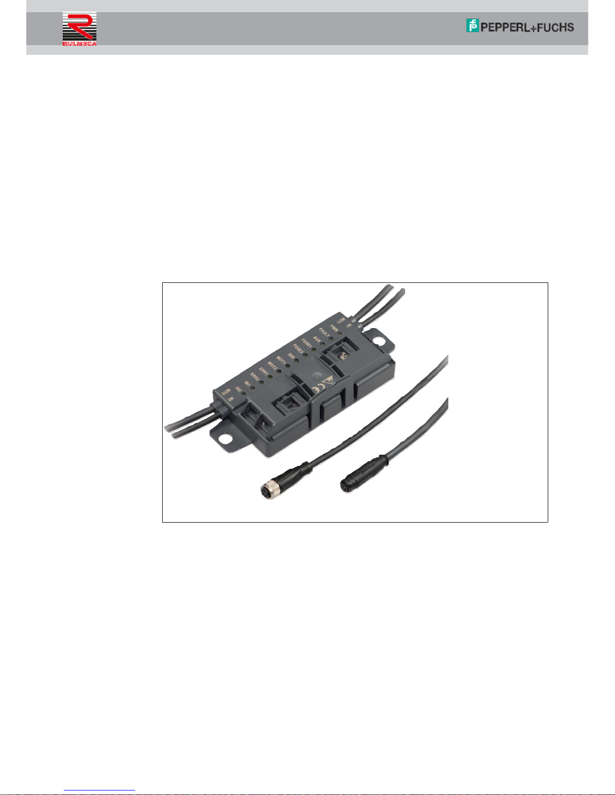
The VBA-4E3A-G20-ZEL/M1L-P2 motor control module is an AS-Interface connection module
for controlling one or two DC roller motors. The module is optimized for type Rulmeca RDR
BL3 motors.
To record statuses in the field environment, the module has two inputs for three-wire sensors
with positive-switching output (PNP) or for mechanical contacts. The input characteristic of the
inputs corresponds to type 1 according to EN 61131-2.
The motors and the sensors are supplied with power via external auxiliary power. This auxiliary
power is supplied to the AS-Interface flat cable of the motor control module via a second flat
cable.
■
The permissible auxiliary power is 18 V ...... 30 V.
■
The sensor power supply may be loaded, in total, with 500 mA.
■
For each motor, a maximum current load of 5 A is permitted.
Figure 4.1 VBA-4E3A-G20-ZEL/M1L-P2 motor control module
7
Page 7
VBA-4E3A-G20-ZEL/M1L-P2
Product Description
Essential function and application characteristics of the motor control module are:
■
Compact housing for direct mounting in support profiles or cable ducts
■
Connection of the motors/sensors via cable outputs with M8 connectors
■
Insulation piercing technology with gold-plated contact pins for contacting the ASInterface flat cable
■
Function displays for the bus, external auxiliary power, status information, inputs, and
outputs
■
Communication monitoring
■
Configurable start/stop ramps for motorcontrol
■
Supply of the connected components from the external auxiliary power
4.2
Housing
The housing is made entirely of plastic, with the exception of the hinge pins for the hinged cable
guide.
The main components are
■
A mounting base with electronics encapsulated in casting resin
■
A folding guide cage as a cable guide for the AS-Interface flat cable.
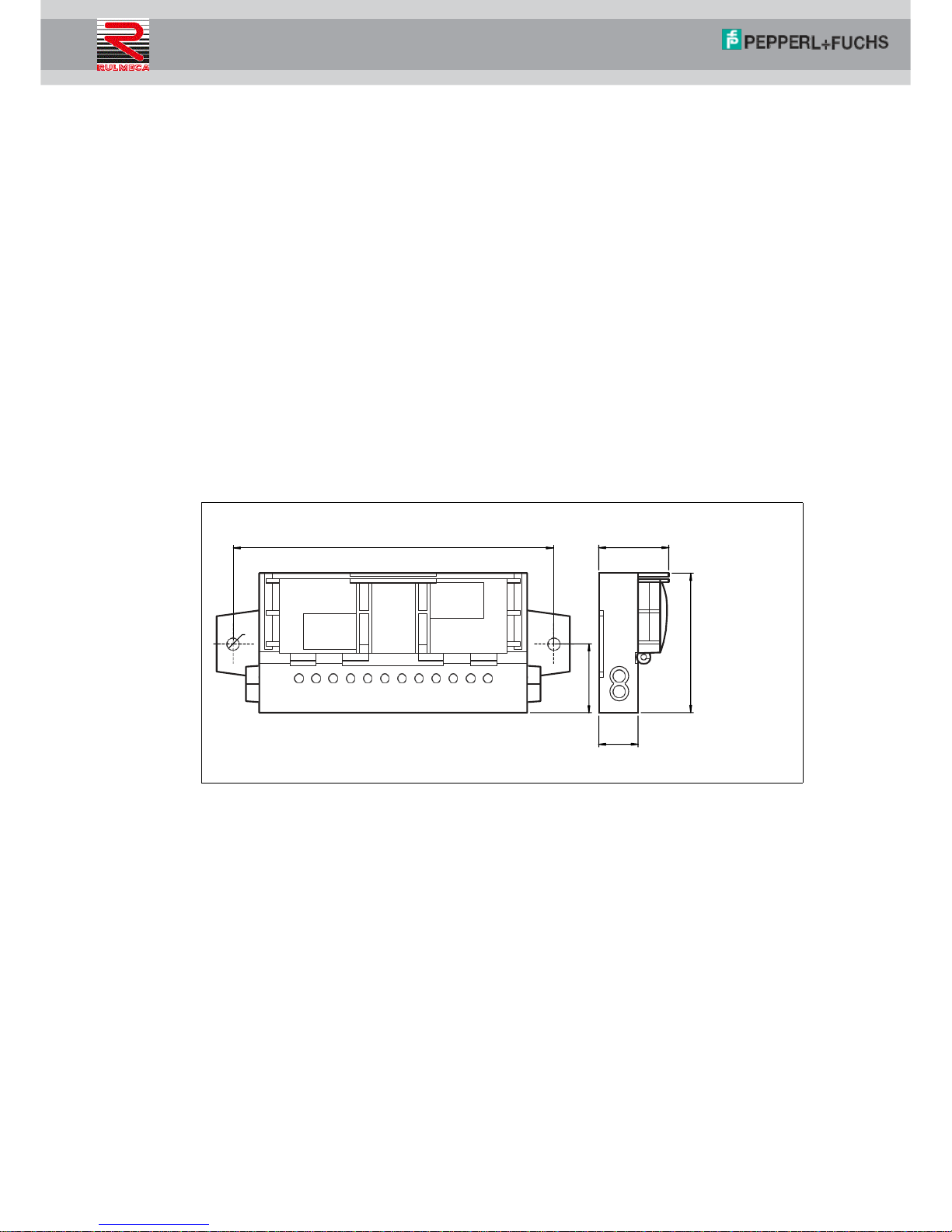
Figure 4.2 Housing dimensions
8
15
Ø 8
27.5
120
27.5
54
Page 8

VBA-4E3A-G20-ZEL/M1L-P2
Product Description
4.3
Indicators and Operating Controls
Figure 4.3 Status indications on the motor controlmodule.
The operating status of the motor control module is displayed via 12 LEDs.
Note!
Additional Flashing Codes during Module Configuration
The following status information relates only to the normal mode of the motor control module. If
you set the motor control module to configuration mode for parameterization, this is indicated
by multiple LEDs flashing. Details can be found in the "Commissioning" chapter.
Status Indication for Start/Stop Ramps
Once the AUX external auxiliary power has been switched on, the motor control module first
shows the number of the stored start/stop ramp. For ramps 1 to 7, the ERR2, IN1, and IN2
LEDs indicate a numerical value in binary code by short flashing. ERR2 LED is the highest
value bit. The LEDs flash five times for 50 ms each time.
If no start/stop ramp is stored, the six MOT1 ... IN2 LEDs flash.
For more information on the start/stop ramps, see "Configuration of Start/Stop Ramps" in the
"Commissioning" chapter.
Start/Stop Ramp Display
Ramp no.
LED MOT1
LED MOT2
LED ERR1
LED ERR2
IN1 LED
IN2 LED
0 Flashes
Flashes
Flashes
Flashes
Flashes
Flashes
1 Off
Off
Off
Off
Off
Flashes
2 Off
Off
Off
Off
Flashes
Off
3 Off
Off
Off
Off
Flashes
Flashes
4 Off
Off
Off
Flashes
Off
Off 5
Off
Off
Off
Flashes
Off
Flashes
6 Off
Off
Off
Flashes
Flashes
Off
7 Off
Off
Off
Flashes
Flashes
Flashes
9
MOT2
MOT1
IN2
IN1
AUX BLACK ASI YELLOW
PWR
FAULT
AUX
FUSE1
FUSE2
DIR
MOT1
MOT2
ERR1
ERR2
IN1
IN2
Page 9

VBA-4E3A-G20-ZEL/M1L-P2
Product Description
Status Indications for AS-Interface and Power Supply
The PWR LED and the FAULT LED show the AS-Interface operating status. Various error
statuses are displayed as a collective error message "Peripheral fault."
Display of the AS-Interface Operating Statuses
LED PWR
Green
LED FAULT
Red Status
On
Off
AS-Interface power supply is OK
Flashes
On
Address = 0
On
On
AS-Interface communication error
Flashes
Flashes
Peripheral fault, collective error message for:
■
AUX external auxiliary power is missing or is inverted
■
Overload of the sensor supply (IN+, IN-)
■
Overload of the speed signal SPEED
Off
Off
AS-Interface voltage missing
The AUX LED shows the status of the AUX external auxiliary power.
Display of the AUX External Auxiliary Power
AUX LED
Red/green
Status
Green on
AUX external auxiliary power is OK
Red on
AUX external auxiliary power is inverted
Off
AUX external auxiliary power voltage is missing
Status Indications for Motor Fuses
The FUSE1 LED for motor 1 and the FUSE2 LED for motor 2 show the status of the power
supplied to the motors.
Motor Fuse Indicator
LED FUSE1
LED FUSE2
Green
Status
On
Power supply for motor is OK
Off
Power supply for motor is missing:
■
Fuse is faulty or
■
AUX external auxiliary power is not connected
Note!
Motor Fuses Are Safety Fuses
Fuses with a 5 A rated current act as protection against short circuits. Each motor is
safeguarded with a fuse. The fuses are not interchangeable. If a fuse is faulty, the module must
be replaced.
10
Page 10

VBA-4E3A-G20-ZEL/M1L-P2
Product Description
Status Indications for Motors MOT1, MOT2
The MOT1, MOT2, ERR 1, ERR2, and DIR LEDs display information about the operating
statuses of the respective motor.
Motor Activity Indicators
LED MOT1
LED MOT2
Yellow
Status
On
Motor is in operation
Off
Motor is off
Motor Fault Indicators
LED ERR1
LED ERR2
Yellow
Status
On
Motor fault is present:
■
Fault output of the motor is active or
■
No motor is connected or
■
Fuse is faulty
Off
No motor fault
Motor Direction of Rotation Indicator
LED DIR
Yellow
Status
On
Direction of rotation to the right (in accordance with RDR BL3,)
Off
Direction of rotation to the left (in accordance with RDR BL3,)
Status Indications for IN1, IN2 Sensors
The IN1 LED for input 1 and IN2 LED for input 2 show the switching statuses of the inputs.
Display of the Inputs
IN1 LED
IN2 LED
Yellow
Status
On
Input is set (high)
Off
Input is not set (low)
4.4
Interfaces and Connections
Flat Cable Specification
The AS-Interface motor control module is compatible with the AS-Interface standard cable in
accordance with IEC 62026-2.
11
Page 11

VBA-4E3A-G20-ZEL/M1L-P2
Product Description
The following AS-Interface cable types are available with UL Recognized approval:
AS-Interface Cable Types with UL Approval
Pepperl+Fuchs
Designation
Color
Sheathing material/
wire insulation
Cross-section
UL "Cable Style"
Approval
VAZ-FK-R-YE
Yellow
TPE/TPE
2x 1.5 mm
2103
VAZ-FK-R-BK
Black
TPE/TPE
2x 1.5 mm
2103
VAZ-FK-PUR-YE
Yellow
PUR(TMPU)/TPM
2x 1.5 mm
20549
VAZ-FK-PUR-BK
Black
PUR(TMPU)/TPM
2x 1.5 mm
20549
Input/Output Connections
The sensors and motors are connected to the motor control module via cables with round M8
connectors:
■
Sensors: socket, four-pin
■
Motors: socket, five-pin
The cable length is 1m.
Motor Supply from Auxiliary Power
The motors are supplied with power directly from the AUX external auxiliary power and this
cannot be switched. The voltage is always on contacts 1 and 3 of the five-pin M8 connector.
Connector Assignment
Connection for
Connectors
Plug type/plug assignment
Sensor
4
2
Input: LF004-GS1-A in accordance with
IEC/EN 61076-2-104
M8, 4-pin, socket, cap nut, coding A
Matching female connector: LM004-Gx1-A
or similar
1: IN+ sensor supply
2: Not used
3: IN- sensor supply
4: IN input
3 1
Motor
4
2
Motor: NF005-SS1-B in accordance with
IEC/EN 61076-2-104
M8, 5-pin, socket, snap lock, coding B
Matching female connector: NM005-Sx1-B
or similar
1: MOT+ motor supply
2: DIR direction of rotation
3: MOT- (=AUX-) motor supply
4: ERROR motor fault
5: SPEED velocity signal
3 1
5
12
Page 12

VBA-4E3A-G20-ZEL/M1L-P2
Installation
5
Installation
5.1
Storage and Transport
For storage and transport purposes, package the unit using shockproof packaging material
and protect it against moisture. The best method of protection is to package the unit using the
original packaging. Furthermore, ensure that the ambient conditions are within allowable range.
5.2
Unpacking
Check the product for damage while unpacking. In the event of damage to the product, inform
the post office or parcel service and notify the supplier.
Retain the original packaging in case the device must be stored or shipped again at a later
date.
Should you have any questions, please direct them to Pepperl+Fuchs.
5.3
Connecting the AS-Interface and Auxiliary Power Flat Cable
The motor control module is connected to the AS-Interface network and the AUX auxiliary
power via the AS-Interface flat cable. The yellow flat cable is for communication and the black
flat cable is for the AUX auxiliary power. The permissible auxiliary power is 18 V ... 30 V.
Contact between the motor control module and flat cables is established via two metal
mandrels and using insulation piercing technology. The flat cables are routed through a hinged
cable guide. When closed, the cable guide is locked using a locking bracket and can be
opened again without the needsfor tools.
The profiled flat cables have a narrow upper side (with a visibly offset profile edge) and a wide
under side (profile edge not visible). The cable guide allows the flat cables to be inserted on
both sides, for flexible connection of flat cables already laid in cable ducts. However, you must
make sure that the profile edge always points to the motor control module. Mechanical reverse
polarity protection prevents complete closure of the cable guide if the flat cable is inserted
incorrectly.
13
Caution!
If one is inserted incorrectly, the motor control module will not work.
If the flat cable is inserted in the cable guide in the wrong direction, the voltage is inverted. The
motor control module will not work. However, internal electrical reverse polarity protection
protects it against breakage.
Page 13

VBA-4E3A-G20-ZEL/M1L-P2
Installation
4 3 5 2
AUX
YELLOW
BLACK
1
Connecting Flat Cables on the Narrow Side
The profile edge is visible from above.
1.
Open the cable guide. To do this, push the locking bracket (1) slightly to one side.
2.
Insert the black AUX flat cable with the profile edge (4) to the motor control module into the
lower guide (see the module tag "Black AUX").
3.
Insert the yellow AS-Interface flat cable with the profile edge (3) to the motor control module
into the upper guide (see the module tag "YELLOW").
4.
Make sure that the profile edges of both flat cables are under the respective reverse polarity
protection (2, 5).
5.
Close the cable guide. It must engage securely in the locking bracket (1).
The metal mandrels contact the strands in the flat cables.
Figure 5.1 Connecting Flat Cables on the Narrow Side
14
Page 14

VBA-4E3A-G20-ZEL/M1L-P2
Installation
Connecting Flat Cables on the Wide Side
The profile edge is not visible from above. For orientation purposes in the figure below, the
edge is shown as a hidden edge drawn with a dotted line.
1.
Open the cable guide. To do this, push the locking bracket (1) slightly to one side.
2.
Insert the black AUX flat cable with the profile edge (3) to the motor control module into the
lower guide (see the module tag "Black AUX").
3.
Insert the yellow AS-Interface flat cable with the profile edge (2) to the motor control module
into the upper guide (see the module tag "YELLOW").
4.
Close the cable guide. It must engage securely in the locking bracket (1).
The profile edges (2, 3) of both flat cables are above the two reverse polarity protections.
The metal mandrels contact the strands in the flat cables.
Figure 5.2 Connecting flat cables on the wide side (profile edge as dotted line)
15
2 3
AUX
YELLOW
BLACK
1
Page 15

VBA-4E3A-G20-ZEL/M1L-P2
Installation
Flat Cable Inserted Incorrectly
The figure below shows an incorrectly inserted flat cable. The profile edge (2) does not point to
the motor control module; the flat cable is therefore inserted with reverse polarity. The flat cable
is located on the reverse polarity protection (1) with a curvature, which means that the cable
guide cannot be closed completely (mechanical reverse polarity protection).
Figure 5.3 Flat cable inserted incorrectly (profile edge as dotted line)
5.4
Connecting Motors and Sensors
Figure 5.4 Connection wiring diagram for motors and sensors
16
1
2
AUX+
AUX-
AUX
5
MOT
1 3
M
4 2
MOT1 & MOT2
MOT+
DIR
ERROR
SPEED
MOT-
1
2
4
5
3 ERR
FAULT
FUSE
DIR
PWR
IN
IN-
(n.c.)
3
2
AS-Interface -
2
1
4
3
IN1 & IN2
1
IN+
4
IN
AS-Interface +
Page 16

VBA-4E3A-G20-ZEL/M1L-P2
Commissioning
6
Commissioning
6.1
AS-Interface Communication
Assigning the AS-Interface Data Bits
Four data bits are available for communication to take place between the motor control module
and the master. Three data bits are available for controlling the motors.
The following designations apply below:
■
DI0...DI3 for AS-Interface input data (motor control module to master)
■
DO0...DO2 for AS-Interface output data (master to motor control module)
DI0...DI03 Motor Control Module to Master
AS-Interface data bit
Input DI
DI0
Fault at output MOT1
DI1
Fault at output MOT2
DI2
Switching status input IN1
DI3
Switching status input IN2
DO0...DO2 Master to Motor Control Module
AS-Interface data bit
Output DO
DO0
Start/stop motor 1
DO1
Start/stop motor 2
DO2
Direction of rotation of motor 1 and motor 2
AS-Interface Communication Monitoring
The motor control module has a watchdog function. If there has been no communication with
the master for more than 40 ms, the motor control module sets the output data DO0...DO2 to
logical 0.
Starting/Stopping Motors (D00, D01)
You can start or stop the motors separately via the DO0 and DO1 bits. To start motors, you must
set the corresponding data bit to logical 1. Via the joint SPEED control signal, the motor control
module actuates the respective motor switched on with an analog voltage value. The SPEED
control signal is released only when DO0 or DO1 data bit is set for the relevant output. The
analog voltage value corresponds to the set speed.
DO0, DO1 Data Bits
Data bit
Status
Function
LED MOT1/2
DO0
1 Start motor 1 (SPEED > 1.5 V)
MOT1: on
0 Stop motor 1 (SPEED < 1.5 V)
MOT1: off
DO1
1 Start motor 2 (SPEED > 1.5 V)
MOT2: on
0 Stop motor 2 (SPEED < 1.5 V)
MOT2: off
Switching the Motor Direction of Rotation (DO2)
You can switch the direction of rotation of the motors using the DIR control signal. The direction
of rotation signal is valid for both motors together. For control purposes, you must parameterize
the DO2 data bit accordingly.
Logical 0, according to RDR BL3, corresponds to direction of rotation to the left. The motor
control module switches the DIR control signal to high impedance.
17
Page 17

VBA-4E3A-G20-ZEL/M1L-P2
Commissioning
Logical 1, according to RDR BL3, corresponds to direction of rotation to the right. The motor
control module switches the DIR control signal to AUX level.
DO2 Data Bit
Data bit
Status
Function
DIR direction of rotation signal
LED DIR
DO2
0 Direction of rotation left
High impedance, approx. 0 V
Off
1 Direction of rotation right
(U
AUX
- 1) V
At idle speed, Ri=5.6 k
On
Adjusting the Motor Speed (P0...P2)
You can adjust the speed for both motors simultaneously only via the P0...P2 parameter bits. To
do this, you must parameterize one of eight predefined speed values. The speed values
correspond to analog voltagevalues.
If the master does not change the parameter bits when the AS-Interface network is switched
on, the eighth speed value (7.26 V) is set per default on the motor control module.
The motor control module issues the set control voltage to the motors via the SPEED control
signal as soon as the motors are switched on via DO0 and DO1 data bits (logical 1). The
control voltage is readjusted by the motor control module and is therefore independent of the
load within certain limits. If the control limits are exceeded due to an excessive load, the motor
control module issues a peripheral fault.
Parameter Bits P0...P2
P2 P1 P0
DO0 (MOT1)
or DO1 (MOT2)
Speed signal SPEED
(Tolerance range)
LED MOT1
or MOT2
x x x 0 < 1.5 V
Off
0 0 0 1 3.96 V (3.92 V .... 4.00 V)
On
0 0 1 1 4.78 V (4.73 V .... 4.83 V)
On
0 1 0 1 5.61 V (5.55 V .... 5.67 V)
On
0 1 1 1 6.44 V (6.38 V .... 6.50 V)
On
1 0 0 1 8.50 V (8.42 V .... 8.59 V)
On 1 0 1 1
9.63 V (9.53 V .... 9.73 V)
On 1 1 0 1
10.00 V (9.90 V .... 10.10 V)
On
1 1 1 1
7.26 V (7.19 V .... 7.33 V)
Basic setting
On
Reporting a Motor Fault (DI0, DI1)
The motor control module records a motor fault via the ERROR status signal. The motor control
module reports faults to the master using DI0 (motor 1) and DI1 (motor 2) data bits. In the event
of a motor fault, the motor control module sets the respective DI0 or DI1 data bit to logical "1."
This status is set if no motor is connected or the motor is not supplied with power if a fuse in the
motor control module is defective.
18
Page 18

VBA-4E3A-G20-ZEL/M1L-P2
Commissioning
DI0, DI1 Data Bits
Data bit
Status
Motor error status
Motor error signal ERROR
LED ERR1/2
DI0 0
No fault in motor 1
U
ERROR
1.2 V, I
ERROR
40 A
ERR1: off
1
■
Fault in motor 1
■
Or motor 1 is not connected
■
Or fuse is defective
High impedance
ERR1: on
DI1 0
No fault in motor 2
U
ERROR
1.2 V, I
ERROR
40 A
ERR2: off
1
■
Fault in motor 2
■
Or motor 2 is not connected
■
Or fuse is defective
High impedance
ERR2: on
Status of the Sensor Inputs (DI2, DI3)
The motor control module transfers the switching statuses of the IN1 and IN2 inputs to the
master using the DI2 (IN1) and DI3 (IN3) data bits.
There is a filter downstream of the inputs that suppresses pulses 2 ms.
DI2, DI3 Data Bits
Data bit
Status
Input switching status
LED IN1/2
DI2
0
Unattenuated, I
IN
0.5 mA
IN1: off
1
Attenuated, I
IN
2.0 mA
IN1: on
DI3
0
Unattenuated, I
IN
0.5 mA
IN2: off
1
Attenuated, I
IN
2.0 mA
IN2: on
6.2
Configuration of the Start/Stop Ramps
Overview
To control the acceleration and to stop the motors, you can set one of eight defined start/stop
ramps for the speed signal SPEED. These ramps always apply to both motors simultaneously.
The ramp duration corresponds to the time from stopping to reaching the maximum speed or
from the maximum speed up to stopping. The inclines of the ramps are constant for each of the
eight ramps and independent of the set speed. The reference value for all ramps is the speed
signal SPEED = 10 V. For a lower parameterized speed, the ramp duration is proportionally
shorter.
Predefined Start/Stop Ramps
Ramp no.
Ramp duration
0 No ramp (default setting)
1 50 ms
2 100 ms
3 200 ms
4 300 ms
5 500 ms
6 1000 ms
7 1500 ms
19
Page 19

VBA-4E3A-G20-ZEL/M1L-P2
Commissioning
The ramp is not effective if the direction of rotation signal is switched when the motor is active.
In this case, the direction of rotation is reversed immediately.
Note!
Default Setting on Delivery
On delivery, ramp no. 0 (no ramp) is the default setting.
Configuring Start/Stop Ramps
To adjust a start/stop ramp, you must change the motor control module to configuration mode.
The motor control module stores a new ramp set in the internal nonvolatile memory. This ramp
is activated automatically every time the motor is switched on. You can reconfigure a ramp as
often as required.
A prerequisite for configuration is that the flat cables for the AS-Interface and AUX are
connected. Communication must already be taking place between the master and motor
control module.
Note!
Configuration Mode Display via LEDs
If the motor control module is in configuration mode, the MOT1, MOT2, ERR1, ERR2, IN1, IN2
LEDs flash simultaneously with a frequency of approx. 2 Hz.
The configuration sequence consists of nine steps. Defined data and parameter values are
transmitted between the master and the motor control module via the DO0...DO2, DI0 ... DI3
data bits andthe P0 .. P2 parameter bits. The master must keep the data and parameter bits
constant for at least 10 ms for each step. Longer intervals are possible as long as a period of
10 s is not exceeded for steps one to six.
The configuration of a new start/stop ramp runs in the following phases:
■
In steps one to six, the master sends parameter values to the motor control module to
activate configuration mode (max. 10 s). DO0.. DO2 must have the value "4" in each step.
■
If the parameter sequence was correct, the motor control module responds to the master
via DI0.. DI2 on the last parameter value with "C
hex
." This response indicates that
configuration mode is activated. The six MOT1 ..IN1 LEDs flash.
■
In step seven, the master sends the selected ramp no. to the motor control module via
DO0 ..DO2.
■
In step eight, the master sends the parameter value "4" to the motor control module via
P0 .. P2. The motor control module stores the ramp number in the nonvolatile memory. It
responds to the master with "A
Hex
" via DI0 ..DI2.
■
In step nine, the master exits configuration mode. The master sends data value "4" via
DO0...DO2 and data value "7" via P0.. P2. The motor control module switches to normal
mode. The six MOT1 ..IN1 LEDs stop flashing.
Note!
Sequence for Command Transmission
For each step, you generally send the data value via DO0.. D02 first and then the parameter
value P0.. P2. The following table shows the contexts of communication between the master
and motor control module. The value "x" represents any of the values in the table.
20
Page 20

VBA-4E3A-G20-ZEL/M1L-P2
Commissioning
Sequence for Configuring a Start/Stop Ramp
Send the following data values and parameter values to the motor control module:
1.
In accordance with steps one to six, for each step send the data value "4" via DO0...DO2 and
then via P0...P2, a value of the parameter string 3,1,6,3,1,6 one after the other.
2.
If configuration mode is active, send the required ramp number via DO0...DO2 and the
parameter value "6" via P0...P2 as step seven.
3.
As step eight, send the ramp number again via DO0...DO2 and parameter value "4" via
P0...P2.
4.
As step nine, send data value "0" via DO0...DO2 and parameter value "7" via P0...P2.
The motor control module has stored the new start/stop ramp and switched back to
normal mode.
Contexts of Module Communication
Step
DO0...DO2
P0...P2
DI0 .. DI3
Comment
4
x x Motor control module in normal mode
1 4 3 x Start activation sequence for configuration mode
2 4 1 x
3 4 6 x
4 4 3 x
5 4 1 x
6 4 6
C
hex
End activation sequence for configuration mode.
Motor control module responds with C
hex
if
configuration mode is OK.
7 Ramp no.
6
C
hex
Transfer of the ramp number to the motor control
module
8 Ramp no.
4
A
hex
The ramp is stored
9 0 7 x Motor control module switches back to normal mode
Troubleshooting during Configuration
The following table describes the behavior of the motor control module if a fault occurs during
the nine-step configuration process.
Fault Scenarios
Step
Possible fault
Motor control module reaction
1 to 6
■
Incorrect data or parameter values or
■
steps 1 to 6 take longer than 10 s
Motor control module remains in normal mode
7 or 8
Incorrect data or parameter values
■
Motor control module responds with "E
hex
"
via DI0 ... DI3 and remains in configuration
mode.
■
The motor control module switches to
normal mode only when the master sends
"0" via DO0 ... DO2 and "7" via P0 ... P2.
■
If "0" or "7" has already been set by the
master in one of these steps, the motor
control module switches to normal mode
immediately without sending a response.
The stored ramp is not changed.
21
Page 21

VBA-4E3A-G20-ZEL/M1L-P2
Troubleshooting
7
Troubleshooting
Fault Information and Remedy
Fault
LED display
Possible cause
Remedy
No data
communication
withAS-Interface
master
PWR off
AS-Interface voltage is missing or
has reverse polarity
Check AS-Interface wiring
PWR flashes and
FAULT on
Module address is 0
Program module address
PWR on and
AS-Interface Master is not
switched on (offline) or
There is duplicate addressing
Switch on the AS-Interface master
FAULT on
or
Check the addresses of all modules
on the AS-Interface segment
Motors will not
start
AUX off
AUX external power supply is
missing
Check AUX voltage and AUX flat
cable
AUX red on
AUX external power supply is
inverted
Correct the polarity of the AUX flat
cable in the cable guide
AUX green on and
FUSE1 (motor 1)
and/or FUSE2
(motor 2) off
Motor fuse is faulty due to
overloading of the motor supply
Replace the motor control module
(cannot be repaired) and remove
the cause of the overload before
starting the motor again
Note: Fault information via ASInterface via DI0 (motor 1) data bit
and/or DI1 (motor 2) data bit and
ERR1 LED on and/or ERR2 LED on
PWR and FAULT
flash alternately
Peripheral fault "Overload speed
signal SPEED":
Motor or motor cable or motor
control module is faulty
Replace motor or motor control
module
FUSE1 (motor 1)
on and/or FUSE2
(motor 2) on and
ERR1 (motor 1) on
and/or ERR2
(motor 2) on
Motor fault: motor is blocked or
faulty
Remove the motor blockage or
replace the motor
Note: Fault information via ASInterface via DI0 (motor 1) data bit
and/or DI1 (motor 2) data bit
Sensors or IN1,
IN2 inputs not
working
AUX off
AUX external power supply is
missing
Check AUX voltage and AUX flat
cable
AUX red on
AUX external power supply is
inverted
Correct the polarity of the AUX flat
cable in the cable guide
PWR and FAULT
flash alternately
Periphery fault: overload on
sensor supply
Check the sensors and eliminate
the overload
22
Page 22

FACTORY AUTOMATION –
SENSING YOUR NEEDS
 Loading...