

Page 1
FACTORY AUTOMATION
MANUAL
VBA-2E-G11-I/U/PT100-F
VBA-2E-G11-I/U/PT100-V1
AS-Interface Analog Module
A
D
Spec 2.1
Page 2

VBA-2E-G11-I/U/PT100-*
With regard to the supply of products, the current issue of the following document is ap-
plicable: The General Terms of Delivery for Products and Services of the Electrical Indus-
try, published by the Central Association of the Electrical Industry (Zentralverband
Elektrotechnik und Elektroindustrie (ZVEI) e.V.) in its most recent version as well as the
supplementary clause: "Expanded reservation of proprietorship"
Page 3

VBA-2E-G11-I/U/PT100-*
1 Introduction................................................................................. 4
2 Declaration of Conformity.......................................................... 5
3 Safety........................................................................................... 6
3.1 Symbols relevant to safety.................................................................. 6
3.2 Intended Use ........................................................................................ 6
3.3 General Safety Instructions................................................................. 6
4 Product Description ................................................................... 7
4.1 Displays and Controls ......................................................................... 7
4.2 Connections ......................................................................................... 8
4.3 Automatic Detection of the Sensor Type ........................................... 9
4.4 Pt100 temperature sensor.................................................................10
5 Installation................................................................................. 11
5.1 Storage and transport........................................................................ 11
5.2 Unpacking........................................................................................... 11
5.3 Mounting............................................................................................. 11
5.4 Connecting the AS-Interface............................................................. 11
5.5 Connecting the Sensors.................................................................... 13
6 Commissioning......................................................................... 14
6.1 Assigning an Address to the Module............................................... 14
6.2 Slave Profile........................................................................................ 14
6.3 Parameterization ................................................................................ 14
7 Troubleshooting........................................................................ 16
7.1 Causes and Elimination of Peripheral Faults .................................. 16
7.2 Cause and elimination of a channel fault ........................................ 16
8 Appendix A................................................................................ 17
8.1 Dimensions......................................................................................... 17
8.2 Technical Data .................................................................................... 17
9 Appendix B................................................................................ 20
9.1 Analog Input Module Measurement Ranges................................... 20
9.2 Delay Times ........................................................................................ 21
3
Page 4
VBA-2E-G11-I/U/PT100-*
Introduction
1Introduction
Congratulations
You have chosen a device manufactured by Pepperl+Fuchs. Pepperl+Fuchs develops,
produces and distributes electronic sensors and interface modules for the market of
automation technology on a worldwide scale.
Before you install this device and put it into operation, please read the operating instructions
thoroughly. The instructions and notes contained in this operating manual will guide you stepby-step through the installation and commissioning procedures to ensure trouble-free use of
this product. By doing so, you:
■
guarantee safe operation of the device
■
can utilize the entire range of device functions
■
avoid faulty operation and associated errors
■
reduce costs from downtimes and incidental repairs
■
increase the effectiveness and operating efficiency of your plant.
Store this operating manual somewhere safe in order to have it available for future work on the
device.
After opening the packaging, please ensure that the device is intact and that the package is
complete.
Symbols used
The following symbols are used in this man ual:
Note!
This symbol draws your attention to important information.
Handling instructions
You will find handling instructions beside this symbol
Contact
If you have any questions about the device, its functions, or accessories, please contact us at:
Pepperl+Fuchs GmbH
Lilienthalstraße 200
68307 Mannheim
Telephone: +49 621 776-4411
Fax: +49 621 776-274411
E-Mail: fa-info@pepperl-fuchs.com
2014-02
4
Page 5

VBA-2E-G11-I/U/PT100-*
ISO9001
Declaration of Conformity
2 Declaration of Conformity
All products were developed and manufactured under observance of the applicable European
standards and guidelines.
Note!
A Declaration of Conformity can be requested from the manufacturer.
The product manufacturer, Pepperl+Fuchs GmbH, 68307 Mannheim, has a certified quality
assurance system that conforms to ISO 9001.
2014-02
5
Page 6
VBA-2E-G11-I/U/PT100-*
Safety
3Safety
3.1 Symbols relevant to safety
Danger!
This symbol indicates an imminent danger.
Non-observance will result in personal injury or death.
Warning!
This sy mbol indicates a possible fault or danger.
Non-observance may cause personal injury or serious property damage.
Caution!
This sy mbol indicates a possible fault.
Non-observance could interrupt devices and any connected facilities or systems, or result in
their complete fa ilure.
3.2 Intended Use
The VBA-2E-G11-I/U/PT100-* is an analog module for connecting 0 V ... 10 V or 0/4 mA ... 20
mA measurement sensors and Pt100 sensors to the AS-Interface network. Measured values
are converted and data transmitted asynchronously as defined by AS-Interface profile 7.3. The
measured values are converted internally at a resolution of 16 bits. The analog module features
two ana log inputs which can be curre nt input, voltage input, or re sistance thermometer inp ut.
The measurement sensors are powered either by the AS-Interface or by the auxiliary power
source.
Read through these instructions thoroughly. Familiarize yourself with the device before
installing, mounting, or operating.
Always operate the device as described in these instructions to ensure that the device and
connected systems function correctly. The protection of operating personnel and plant is only
guaranteed if the device is operated in accordance with its intended use.
3.3 General Safety Instructions
Only instructed specialist staff may operate the device in accordance with the operating
manual.
User modification and or repair are dangerous and will void the warranty and exclude the
manufacturer from any liability. If serious faults occur, stop using the device. Secure the device
against inadvertent operation. In the event of repairs, return the device to your local
Pepperl+Fuchs representative or sales office.
The connection of the device and maintenance work when live may only be carried out by a
qualified electrical specialist.
The operating company bears responsibility for observing locally applicable safety regulations.
Store the not used device in the original packaging. This offers the device optimal protection
against impact and moisture.
Ensure that the ambient conditions comply with regulations.
Note!
Disposal
Electronic waste is hazardous waste. When disposing of the equipment, observe the current
statutory requirements in the respective country of use, as well as local regulations.
2014-02
6
Page 7
VBA-2E-G11-I/U/PT100-*
2
T
P
VBA-2E-G11-I/U/PT100
AUX
AS-i
FAULT
R
D
D
A
1
T
P
I
1
I
2
U
2
U
1
INT
EXT
1
3
2
4
6
5
7
1
3
5
6
7
7
Product Description
4Product Description
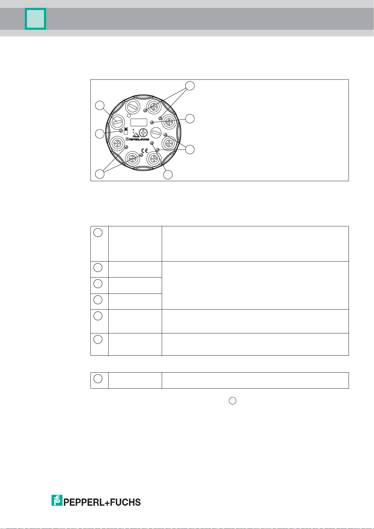
4.1 Displays and Controls
Figure 4.1 Display and control elements
The VBA-2E-G11-I/U/PT100-* analog module is equipped with the following displays and
controls:
LED Indicator
AS-i/FAULT LED Status indication; multicolor LED
2
Green: normal mode
Red: communication error
Flashing yellow/red: address 0
Flashing green/red: peripheral fault
PT1 LED
PT2 LED
I1 LED
I2 LED
Status of input signal; yellow LED
Off: not active
On: signal within measurement range
Flashing: signal outside measurement range
U1 LED
U2 LED
AUX LED Ext. auxiliary power source (U
4
Green: voltage OK
); dual LED (green/red)
AUX
Red: voltage reversed
INT/EXT LED Status indication, input supply; green LED
Green: internal input supply
Off: external input supply
Switch
INT/EXT switch
Set to INT: sensors powered via the AS-Interface (max. 140 mA)
Set to EXT: sensors powered via an auxiliary power source (max. 600 mA)
In order to reach the switch, remove the bli nd plug
2014-02
7
Page 8
VBA-2E-G11-I/U/PT100-*
2
T
P
VBA-2E-G11-I/U/PT100
AUX
AS-i
FAULT
R
D
D
A
1
T
P
I
1
I
2
U
2
U
1
INT
EXT
4
3
1
2
1
4
3
12
5
2
3
4
2
T
P
VBA-2E-G11-I/U/PT100
AUX
AS-i
FAULT
I
-
S
A
1
T
P
I
1
I
2
U
2
U
1
INT
EXT
X
U
A
4
3
1
2
1
4
3
12
5
2
3
4
1
34
2
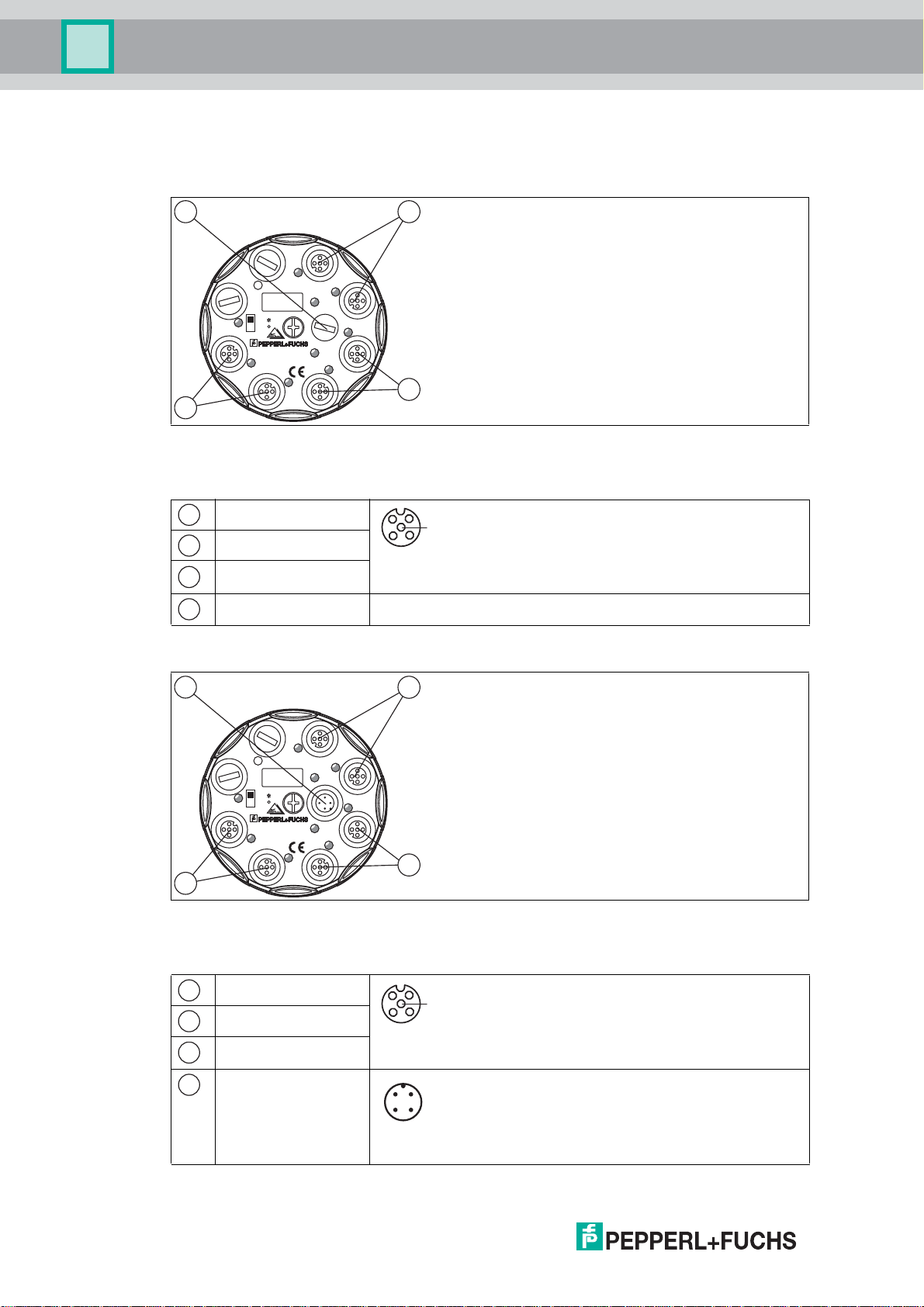
Product Description
4.2 Connections
VBA-2E-G11-I/U/PT100-F
Figure 4.2 Connections VBA-2E-G11 -I/U/PT100- F
The VBA-2E-G11-I/U/PT100-F analog module is equipped with the following connections:
Pt100 inputs
: functional ground
Current inputs
Volt age i nputs
M12 round plug connector
Addressing socket Low voltage switch socket, 1.3 mm
VBA-2E-G11-I/U/PT100-V1
Figure 4.3 Connections VBA-2E-G11 -I/U/PT100-V1
The VBA-2E-G11-I/U/PT100-V1 analog module is equipped with the following connections:
8
Pt100 inputs
: functional ground
Current inputs
Volt age i nputs
AS-Interface/U
AUX
M12 round plug connector
1: AS-Interface +
2: AUX 3: AS-Interface 4: AUX +
M12 round plug connector
2014-02
Page 9

VBA-2E-G11-I/U/PT100-*
1
2
3
4
Product Description
Note!
Switching Off the Second Channel
Figure 4.4 Input PT2 bridge
Two bridges are plugged in at the PT100 input PT2 by default; these bridges are designed to
switch off channel 2. Remove the bridges to use channels 1 and 2.
The bridges must be plugged in and disconnected only when the module is de-energized!
4.3 Automatic Detection of the Sensor Type
The VBA-2E-G11-I/U/PT100-* analo g input module automatically detects which sensor type is
connected. The types of sensors that can be connected are: 0 V ... 10 V measurement
sensors, 0/4 mA ... 20 mA-measurement sensors, or Pt100 temperature sensors. The sensor
type is automatically detected once switched on. Once the module has detected the sensor
type, the corresponding module configuration is activated.
All input LEDs are illuminated during the first few seconds after switching on. During this time,
the module evaluates the connected sensor type on the basis of various measured values. The
signal values that ensure unambiguous detection of the type of sensor connected are:
■
Voltage: 1 V ... 11.5 V
■
Current: 1 mA ... 23 mA
■
Pt100: -219 °C ... 884 °C
If the module cannot clearly establish which sensor type is connected, the last detected sensor
type is provisionally activated. For example, the module may not detect which sensor type is
connected if the signal values are not within the specified thresholds or if two different sensor
types are simultaneously applied to one channel.
A specific sensor type is finally activated when the signal values measured are within the
specified thresholds.
Note!
The Pt100 Input Is an Exception:
The Pt100 sensor type is only activated if a Pt100 temperature s ensor is connected to the
PT100 inputs before switching on. The Pt100 sensor type cannot be activated during operation
or a ctivated provis ionally.
Note!
If you connect two different sensor types to one channel simultaneously, fault-free operation is
not guaranteed. The module will not be damaged by this.
2014-02
9
Page 10

VBA-2E-G11-I/U/PT100-*
50
100
150
200
250
300
350
400
Resistance [Ω]
Temperature [°C]
Pt100
Curve Resistance Thermometer Pt100
0 100 200 300 400 500 600 700 800 900
Product Description
4.4 Pt100 temperature sensor
Pt100 temperature sensors are platinum resistance thermom eters complying with standard
IEC 751 / DIN EN 60751. In this standard, various values of the temperature sensor are
defined. The nominal resistance of the Pt100 is 100 , measured at 0 °C. Furthermore, as well
as other values, the mean temperature coefficient of 0°C to 100 °C is also defined. The mean
temperature coefficient defines the mean change in resistance relative to the nominal
resistance. The analog module calculates the corresponding temperature based on the
measured resistance of the temperature sensor.
Figure 4.5 Curve Pt100
2014-02
10
Page 11

VBA-2E-G11-I/U/PT100-*
4.8
50
60
Ø 85.8
metal insert
Installation
5 Installation
5.1 Storage and transport
For storage and transport purposes, package the unit using shockproof packaging material
and protect it against moisture. The best method of protection is to package the unit using the
original packaging. Furthermore, ensure that the ambient conditions are within allowable range.
5.2 Unpacking
Check the product for damage while unpacking. In the event of damage to the product, inform
the post office or parcel service and notify the supplier.
Retain the original packaging in case the device must be stored or shipped again at a later
date.
Should you have any questions, please direct them to Pepperl+Fuchs.
5.3 Mounting
Align the device as required and secure to a flat mounting surface by screwing it in place with
two M4 mounting screws. When the central screw is tightened, the functional ground of the
M12 round plug connector connects with the metal insert in the mounting base. Ensure that this
metal insert is connected with the protective ground via the mounting screws. The mounting
screws are not included.
Figure 5.1
Screw a blind plug onto unused connections to ensure the relevant degree of protection. The
recommended tightening torque for securing blind plugs is 0.4 Nm.
5.4 Connecting the AS-Interface
VBA-2E-G11-I/U/PT100-F
The VBA-2E-G11-I/U/PT100-F is connected with the AS-Interface network via the yellow flat
cable. The external auxiliary power source U
cable where required.
Connecting to the AS-Interface
1. Open the module by unscrewing the central screw.
2014-02
2. Place the yellow flat cable in the channel labeled AS-i.
is connected to the module via the black flat
AUX
11
Page 12

VBA-2E-G11-I/U/PT100-*
1
2
Installation
3. If the module is to be powered via an external auxiliary power source U
flat cable in the channel labeled AUX. Set the INT/EXT switch to EXT.
If the module is to be powered solely by the AS-Interface, place the flat cable seal (VAZ-FKS-BK-SEAL) in the channel labeled AUX. The flat cable seal ensures compliance with the
protection class.
1. AS-i channel (yellow flat cable)
2. AUX channel (black flat cable)
3. Ensure the flat cable is position ed correctly.
4. Reattach the upper part of the module.
5. Tigh ten the central screw. T he re commended tigh te ning torque for th is sc rew is 1 .8 Nm .
, place the black
AUX
The AUX LED and the AS-i/FAULT LED illuminate in green when the module is
connected to th e AS-Inte rface and th e externa l a uxiliary powe r source U
AUX
.
VBA-2E-G11-I/U/PT100-V1
The VBA-2E-G11-I/U/PT100-V1 is connected to the AS-Interface network and the external
auxiliary power source U
via the M12 connector. see chapter 4.2.
AUX
12
2014-02
Page 13

VBA-2E-G11-I/U/PT100-*
Connection examples:
Pt100
2-wire
Pt100
4-wire
Current input
Voltage input
Pt100 input
Inputs:
3-wire 4-wire
24 V
U+
U0 V
+
Sig
-
+
Sig+
Sig-
-
1
2
4
3
ϑ
ϑ
I1/I2
U1/U2
PT1/PT2
2-wire 3-wire 4-wire
24 V
I+
I0 V
+
-
+
Sig
-
+
Sig+
Sig-
-
1
2
4
3
4
3
12
5
4
3
12
5
4
3
12
5
+
PT+
PT-
-
1
2
4
3
Installation
5.5 Connecting the Sensors
Figure 5.2
2-wire, 3-wire, and 4-wire sensors can be connected to the VBA-2E-G11-I/U/PT100-* module.
Suitable for various connection scenarios see Figure 5.2 on page 13. In order to obtain a
sound measurement result, the difference in voltage between pins 3 and 4 on a 4-wire
measurement (2 V) must not be exceeded.
Note!
Connection Instructions
Use shielded cables to connect the sensors.
Note!
Pin 5 of the M12 round plug connector is the functional ground. When the central screw is
tig htened, p in 5 connects with the metal insert in the mounting bas e. se e cha pter 5.3. This
metal insert then ma kes contact with the mounting surfa ce via the m ou nting screws .
2014-02
13
Page 14

VBA-2E-G11-I/U/PT100-*
Commissioning
6 Commissioning
6.1 Assigning an Address to the Module
To operate the VBA-2E-G11-I/U/PT100-* in an AS-Interface network, you must assign a
suitable address to the AS-Interface slave. The AS-Interface VBP-HH1-V3.0 handheld device
by Pepperl+Fuchs or an AS-Interface master can be used to assign addresses.
The VBA-2E-G11-I/U/PT100-* module is a standard slave as defined by specification 2.1.
These modules can be assigned addresses 1 to 31. The default address on deliver y is 0.
6.2 Slave Profile
The VBA-2E-G11-I/U/PT100-* has the profile
S-7.3.D
I/O = 7
ID = 3
ID1 = F (programmable)
ID2 = D
The data value is transmitted as defined by AS-Interface profile 7.3.
6.3 Parameterization
The following parameters can be set for the VBA-2E-G11-I/U/PT100-*. Program the
parameters using an AS-Interface master, with the VAZ-SW-ACT32 AS-i Control Tool from
Pepperl+Fuchs or with the VBP-HH1-V3.0 handheld device.
Parameter P0: 50/60 Hz Filter
Default value P0=1, active
With parame ter P0, you activate the filter for 50/6 0 Hz power frequencies. With an ac tivated
filter, power frequency interference is suppressed. In this case, the conversion time is extended
(see chapter 9.2).
Parameter P1: Second Channel
Default value P1=1, active
Parameter P1 is used to switch the second measuring channel on or off. If the second channel
is switched off, this can considerably reduce the conversion time in the module. (see chapter
9.2)
Alternatively, it is poss ible to con trol the secon d channel via the bridge s on input PT2. (see
chapter 4.2)
Note!
The bridges on input PT2 override parameter P1.
14
2014-02
Page 15

VBA-2E-G11-I/U/PT100-*
Commissioning
Para meter P2: Peripheral Fault
Default value P2=1, active
Parameter P2 is used to switch notification of a peripheral fault in the event of a measuring
ove rrange on o r off (see c hapter 9 ). If notificatio ns are activated, the AS-i/FAULT L ED flashes in
the event of a peripheral fault, and a notification is sent to the master.
A peripheral fault is always reported if:
■
The power supply is overloaded.
■
The external power supply is not available when the INT/EXT switch = EXT.
Parameter P3: Current Input 0 mA ... 20 mA
Default value P3=1, not active
Parameter P3=0 is used to se t both input channels to current mode . W ire b reak detection is
simultaneously deactivated. (see chapter 9.1)
2014-02
15
Page 16

VBA-2E-G11-I/U/PT100-*
Troubleshooting
7 Troubleshooting
7.1 Causes and Elimination of Peripheral Faults
A peripheral fault (P fault) is indicated by the color and flashing of the AS-i/FAULT LED. There
are various causes of and solutions for correcting peripheral faults.
Cause Solution
Sensor supply overload
Measured values outside the
measurement range
Auxiliary power too low (switch set to
EXT)
If none of these potential solutions correct the peripheral fault, please contact Pepperl+Fuchs.
7.2 Cause and elimination of a channel fault
If channel 2 is not transferred and the LED at the connection of the relevant input of channel 2 is
not illuminated, channel 2 is not activated.
■
Check sensor supply for short circuit
■
Check the connected measurement sensor/Pt100
temperature sensor for wire br ea k/sh or t c ircuit
■
Check the auxiliary power source
Cause Solution
Jumper plugged at PT100-input PT2
Parameter P1=0
■
Remove jumper (see chapter 4.2)
■
Change pa ra mete r P 1 (see chapter 6.3)
16
2014-02
Page 17

VBA-2E-G11-I/U/PT100-*
D
l
c
H
Appendix A
8Appendix A
8.1 Dimensions
Ty p e D H
VBA-2E-G11-I/U/PT100-F 85 mm 35 mm -
VBA-2E-G11-I/U/PT100-V1 85 mm 35 mm 11 mm
8.2 Technical Data
Ge n er a l D a ta
Slave type Sta nd a rd sla ve
AS-Interfac e specification V3.0
Required master
specific ation
UL file number E87056
Display/Controls
AS-i/FAULT LED Status indication; multicolor LED
ANALOG LED Status of input signal; yellow LED
AUX LED Ext. auxiliary power source (U
INT/EXT LED Status indication, input supply; green LED
V2.1
Green: normal mode
Red: communication error
Flashing yellow/red: address 0
Flashing green/red: peripheral fault
Off: not active
On: signal within measurement range
Flashing: signal outside measurement range
); dual LED (green/red)
Green: voltage OK
Red: voltag e reversed
Green: input supply from AS-Interface
Off: input supply from auxiliary power source
AUX
l
c
Electrical Data
Auxiliary power (output) 20 VDC ... 30 VDC PELV
Rated operational voltage 26.5–31.6 V from AS-Interface
Rated operating curren t 60 mA (without sensors)/max. 200 mA
Protection class III
Surge protection U
2014-02
, Ue: Overvoltage category III, securely isolated power
AUX
supplies (PELV)
17
Page 18

VBA-2E-G11-I/U/PT100-*
Appendix A
Input
Number/type Two analog inputs
Power supply From AS-Interface (switch setting INT, basic setting) or from
Current rating 140 mA from AS-Interface; overload and short-circuit proof
Input resistance Current input: max. 70
Measurement current For Pt100: approx. 1 mA
Measurement accuracy Voltage/current: 0.1% of end value
Resolution 16 bit/1 µA (current input) or
Temperature effect Voltage/current: 20 ppm/K
Current: 4 mA ... 20 mA/4 mA ... 20 mA
Voltage: 0 V ... 10 V
Pt100: -200 °C ... 850 °C
auxiliary power source U
600 mA from external auxiliary power source U
and short-circuit proof
Voltage input: 100 k
Pt100: 0.1% of temperature displayed [°C] + 0.3 °C
16 bit/1 mV (voltage input) or
16 bit/0.1 °C (temperature input)
Pt100: (10 ppm of temperature displayed [°C] + 0.003 °C)/K
(switch setting EXT)
AUX
, overload
AUX
Program ming Instructions
Profile S-7.3.D
IO code 7
ID code 3
ID2 code D
Data bit (function via ASInterface)
Parameter bit
(programmable via AS-i)
P0 50/60 Hz filter
P1 Programming the second chann el
P2 Notification of peripheral fault in the event of a measuring
P3 P3=1, normal operation
The data value is transmitted as defined by AS-Interface profile
7.3.
Func tio n
P0=1 , activated
P0=0, deactivated
P1=1, channel 2 is programmed
P1=0, channel 2 is not programmed
overrange
P2=1, peripheral fault is reported
P2=0, peripheral fault is not reported
P3=0, both channels in current mode and without wire break
detection
18
2014-02
Page 19

VBA-2E-G11-I/U/PT100-*
Appendix A
Compliance with Standards and Directives
Directive conformity
EMC Directive
2004/108/EC
Stand a rd confo r m i ty
Noise immunity EN 61000-6-2:2005, EN 61326-1:2006, IEC 62026-2:2008
Emitte d inte rference EN 61000-6-4:2007
Input EN 61131-2:2007
Degree of protection EN 60529:2000
Fieldbus standard EN 50295:1999, IEC 62026-2:2008
Ambient conditions
Ambient temperature -25 °C ... 70 °C (-13 °F ... 158 °F)
Storage temperature -25 °C ... 85 °C (-13 °F ... 185 °F)
Mechanical Data
Device VBA-2E-G11-I/U/PT100-F VBA-2E-G11-I/U/PT100-V1
Connection AS-Interface/U
Degree of protection IP68/IP69K
Material
Housing PBT PC
Mounting screw Stainless steel 1.4305/AISI 303 (V2A)
Mass 200 g
Mounting Mounting base
EN 50295:1999
: insulation
piercing technology, yellow flat
cable/black flat cable
Inputs: M12 round plug
conn ectors
AUX
AS-Interface/U
plug connector
Inputs: M12 round plug
connectors
: M12 round
AUX
2014-02
19
Page 20

VBA-2E-G11-I/U/PT100-*
Appendix B
9 Appendix B
9.1 Analog Input Module Measurement Ranges
Current Input Measurement Ranges
The measurement range of the current input can be set via AS-Interface parameter P3:
■
P3=1, nominal range 4 mA ... 20 mA
■
P3=0, nominal range 0 mA ... 20 mA
Current: 4 mA ... 20 mA
Input signal [mA] Display on the master Input LED
> 23 32767 Flashing Above threshold
20.001–23 20001–23000 On
4 ... 20 4000 ... 20000 On Nominal range
1 ... 3999 1000 ... 3999 On
< 1 32767 Flashing Below threshold
Table 9.1 Measurement range 1 mA ... 23 mA
1)
: Measurement accuracy corresponds to the nominal range
(peripheral fault)
Extended range
Extended range
(peripheral fault)
1)
1)
Current: 0 mA ... 20 mA
Input signal [mA] Display on the master Input LED
> 23 32767 Flashing Above threshold
(peripheral fault)
20.001 ... 23 20001 ... 23000 On
Extended range
0 ... 20 0000 ... 20000 On Nominal range
< 0 0000 On Below threshold
Table 9.2 Measurement range 0 mA ... 23 mA
1)
: Measurement accuracy corresponds to the nominal range
Caution!
Maximum input current
At input currents > 80 mA, fault-free operation of all inputs is not guaranteed.
Voltage Input Measurement Ranges
Voltage: 0 V ... 10 V
Input signal [V] Display on the master Input LED
> 11.5 32767 Flashing Above threshold
(peripheral fault)
10.001 ... 11.5 10001 ... 11500 On
0 ... 10 0000 ... 10000 On Nominal range
<0 0000 On Below threshold
Table 9.3 Measurement range 0 V ... 11.5 V
1)
: Measurement accuracy corresponds to the nominal range
Extended range
1)
1)
20
2014-02
Page 21

VBA-2E-G11-I/U/PT100-*
Module
Analog-to-digital conversion
Channel 1
Analog-to-digital conversion
Channel 2
Analog-to-digital conversion
Channel 1
Transmission
Channel 1
Transmission
Channel 2
Transmission
Channel 2
Transmission
Channel 1
Conversion time
~ Transmission time x 3
Network
Appendix B
Caution!
Maximum input voltage
The input voltage at the voltage input must not exceed 50 V.
Pt100 Input Measurement Ranges
Pt100: -200 °C ... 850 °C
Input signal [V] Display on the master Input LED
> 884°C 32767 Flashing Above threshold
850.1 °C ... 884 °C 8501 ... 8840 On
-200 °C ... +850 °C
(18.52
-219.4 °C ... -200.1 °C -2194 ... -2001 On
< -219.4 °C 32767 Flashing Below threshold
Table 9.4 Measurement range -219.4 °C ... 884 °C
1)
: Measure ment accuracy corresponds to the nominal range
(peripheral fault)
Extended range
-2000 ... 8500 On Nominal range
Extended range
(peripheral fault)
1)
1)
9.2 Delay Times
The VBA-2E-G11-I/U/PT100-* needs a certain amount of time for the conversion and
transmission of the analog measuring signals on the AS-Interface master. This period of time is
mainly composed of the conversion time and the transmission time. The conversion time and
transmission time depend on a number of factors.
Latency
Latency = delay of a signal under worst case conditions.
The analog-to-digital conversion in the analog module and the transmission via AS-Interface is
not in sync. In the worst case, the transmission of a channel via AS-Interface starts just before
the conversion of this channel is completed within the module. This gives rise to two scenarios:
1. The conversion time is longer than the transmission time
Latency = Conversion time + Transmission time * (Number of channels +1)
2. The con vers io n time is shorter than the transm is si on time
Latency = Conversion time * (Number of channels +1) + Transmission time
1st
2014-02
Figure 9.1 Conversion time > Transmission time
21
Page 22

VBA-2E-G11-I/U/PT100-*
Transmission
Channel 1
Transmission
Channel 2
Transmission
Channel 1
~ Conversion time x 3
Transmission time
Network
Analog-to-digital
conversion
Channel 1
Analog-to-digital
conversion
Channel 2
Analog-to-digital
conversion
Channel 1
Analog-to-digital
conversion
Channel 2
Module
Appendix B
2nd
Figure 9.2 Conversion time < Transmission time
Conversion time
The conversion time is the time that the module requires to convert an analog signal into a
digital value. The conversion time depends heavily on parameter P0
50/60 Hz filter inactive (P0=0) 10 ms
50/60 Hz filter active (P0=1) 70 ms
Tab l e 9.5
Transmission time
The transmission time is based on the AS-Interface specification. The AS-Interface transmits
data in 4-bit packe ts. At values greater th an 4 b its, the qu antity of data i s divided into smaller
values and then transmitted to a com unit over several cycles. If several channels are
transmitted per slave, the number of cycles increases. The transmission time is the time
required to fully transmit a digital data volume to the com unit. In the profile 7.3, seven frames
are required per channel.
The duration of a cycle depends on the number of occupied addresses in the AS-interface
network. An address is conside red o ccupied if one of the following configurations apply:
■
A standard address is assigned (e. g. 1)
■
An A- or B-Address is assigned (e. g. 1A or 1B)
■
An A- and a B-Address are assigned (e. g. 1A and 1B)
When calculating the cycle time, each of these configurations assumed to be one occupied
address.
22
Cycle time = 150s * ([Number of occupied addresses] +2)
The transm ission time is 7 cycles:
Tr a n smi s s i o n t ime = 1 5 0s * ([Number of occupied addresses] +2) * 7
Example:
In a network, the addresses of 1A, 1B, 2A and 3 are assigned. For the calculation of the
transmission time this corresponds to 3 occupied addresses. Thus we have:
Tr a n smi s s i o n t ime = 1 5 0s * (3 +2) * 7 = 5,25 ms
■
4 occupied addresses: Transmission time = 6,3 ms
■
31 occupied addresses: Transmission time = 35 ms
2014-02
Page 23

VBA-2E-G11-I/U/PT100-*
Appendix B
2014-02
23
Page 24

Subject to modifications
Copyright PEPPERL+FUCHS • Printed in Germany
www.pepperl-fuchs.com
FACTORY AUTOMATION –
SENSING YOUR NEEDS
Worldwide Headquarters
Pepperl+Fuchs GmbH
68307 Mannheim · Germany
Tel. +49 621 776-0
E-mail: info@de.pepperl-fuchs.com
USA Headquarters
Pepperl+Fuchs Inc.
Twinsburg, Ohio 44087 · USA
Tel. +1 330 4253555
E-mail: sales@us.pepperl-fuchs.com
Asia Pacific Headquarters
Pepperl+Fuchs Pte Ltd.
Company Registration No. 199003130E
Singapore 139942
Tel. +65 67799091
E-mail: sales@sg.pepperl-fuchs.com
/ TDOCT2097E_ENG
02/2014
 Loading...