

Page 1
A
D
Spec 2.1
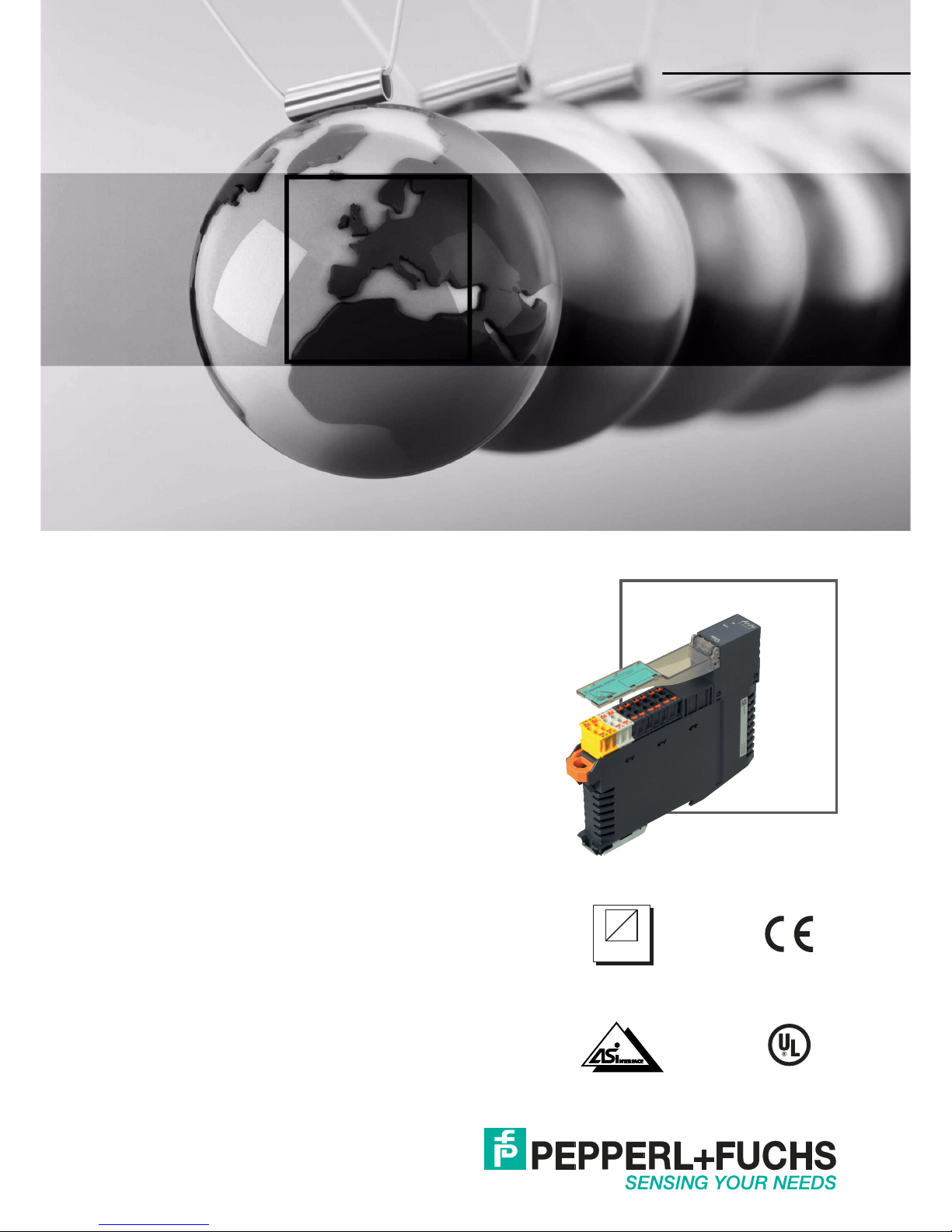
VBA-2A-KE5-IL/UL,
VBA-4A-KE5-IJL/UJL
AS-Interface Analog Modules
FACTORY AUTOMATION
MANUAL
Page 2

With regard to the supply of products, the current issue of the following document is ap-
plicable: The General Terms of Delivery for Products and Services of the Electrical Indus-
try, published by the Central Association of the Electrical Industry (Zentralverband
Elektrotechnik und Elektroindustrie (ZVEI) e.V.) in its most recent version as well as the
supplementary clause: "Expanded reservation of proprietorship"
VBA-2A-KE5-IL/UL, VBA-4A-KE5-IJL/UJL
Page 3

VBA-2A-KE5-IL/UL, VBA-4A-KE5-IJL/UJL
3
1 Introduction................................................................................. 5
1.1 Content of this Document ................................................................... 5
1.2 Target Group, Personnel...................................................................... 5
1.3 Symbols Used ...................................................................................... 6
2 Certificates and Approvals ........................................................ 7
2.1 UL Information...................................................................................... 7
3 Product Description ................................................................... 8
3.1 Intended Use ........................................................................................ 8
3.2 Displays and Operating Elements ...................................................... 8
3.3 Connections ....................................................................................... 10
3.4 Configuring the Output Function on the VBA-2A-KE5-IL/UL ......... 10
3.5 Configuring the Output Function on the VBA-4A-KE5-IJL/UJL ..... 11
3.6 Resetting/Restarting Automatic Detection ...................................... 12
4 Installation................................................................................. 13
4.1 Storage and Transport ....................................................................... 13
4.2 Unpacking........................................................................................... 13
4.3 Mounting ............................................................................................. 13
4.4 AS-Interface and AUX Auxiliary Voltage Connection ..................... 13
4.5 Connecting Actuators........................................................................ 14
5 Commissioning......................................................................... 15
5.1 Assigning an Address to the Module............................................... 15
5.2 Slave Profile........................................................................................ 15
5.3 Parameterization ................................................................................ 15
6 Troubleshooting........................................................................ 18
6.1 Causes and Elimination of a Peripheral Fault ................................. 18
6.2 Causes and Elimination of an Actuator Fault .................................. 18
Page 4

4
VBA-2A-KE5-IL/UL, VBA-4A-KE5-IJL/UJL
7 Appendix A................................................................................ 19
7.1 Value Ranges of the Analog Output Modules..................................19
7.2 Delay Times.........................................................................................19
Page 5

VBA-2A-KE5-IL/UL, VBA-4A-KE5-IJL/UJL
Introduction
2018- 07
5
1 Introduction
1.1 Content of this Document
This document contains information required to use the produ ct in the relevant phases of the
product life cycle. This may include information on the following:
■
Product identification
■
Delivery, transport, and storage
■
Mounting and installation
■
Commissioning and operation
■
Maintenan ce and repair
■
Troubleshooting
■
Dismounting
■
Disposal
The documentation comprises the following parts:
■
This document
■
Datasheet
In addition, the documentation may comprise the following parts, if applicable:
■
EU-type examination certificate
■
EU declaration of conformity
■
Attestation of conformity
■
Certificates
■
Control drawings
■
Instruction manua l
■
Other documents
1.2 Target Group, Personnel
Responsibility for planning, a ssembly, commissioning, operation, maintenance, and
dismounting lies with the plant operator.
Only appropriately trained and qualified personnel may carry out mounting, installation,
commissioning, operation, maintenance, and dismounting of the product. The personnel must
have read and understood the instruction man ual and the further docum entation.
Prior to using the product make yourself familiar with it. Read the document carefully.
Note!
For full information on the product, refer to the further documentation on the Internet at
www.pepperl-fuchs.com.
Page 6
2018- 07
6
VBA-2A-KE5-IL/UL, VBA-4A-KE5-IJL/UJL
Introduction
1.3 Symbols Used
This document contains symbols for the identification of warning messages and of informative
messages.
Warning Messages
You will find warning messages, whenever dangers may arise from your actions. It is mandatory
that you observe these warning messages for your personal safety and in order to avoid
property damage.
Depending on the risk level, the warning messages are displayed in descending order as
follows:
Informative Symbols
Action
This symbol indicates a paragraph with instructions. You are prompted to per form an action or
a sequence of actions.
Danger!
This symbol indicates an imminent danger.
Non-observance will result in personal injury or death.
Warning!
This symbol indicates a possible fault or danger.
Non-observance may cause personal injury or serious property damage.
Caution!
This symbol indicates a possible fault.
Non-observance could interrupt the device and any connected systems and plants, or result in
their complete failure.
Note!
This symbol brings important information to your attention.
Page 7

VBA-2A-KE5-IL/UL, VBA-4A-KE5-IJL/UJL
Certificates and Approvals
2018- 07
7
2 Certificates and Approvals
2.1 UL Information
Technical Data and Environmental Conditions
This device is for indoor use only.
This device may be operated in altitudes up to 2000 m .
The ambient temperature range is from -25 °C to +70 °C.
The device must be installed in accordance with applicable national laws and regulations.
If the device is used in a manner not specified by the manufacturer, the protection provided by
the equipment may be impaired.
The device must be installed in a switch cabinet or switch box that meets protection class IP54
as a m inimum.
Page 8

2018- 07
8
VBA-2A-KE5-IL/UL, VBA-4A-KE5-IJL/UJL
Product Description
3 Product Description
3.1 Intended Use
The VBA-2A-KE5-IL/UL features two analog outputs. These outputs can be configured as
current outputs (0 mA ... 20 mA) or as voltage outputs (0 V ... 10 V). The outputs are configured
as current outputs by default. The outputs are supplied via the external auxiliary voltage.
Analog value conversion and data transfer are provided asynchronously according to ASInterface profile 7.3. The rise time of the analog signals is approximately 2 ms.
The VBA-4A-KE5-IJL/UJL features four analog outputs. These outputs can be configured as
current outputs (0 mA ... 20 mA) or as voltage outputs (0 V ... 10 V). The module features
automatic output detection, which allows outputs to be operated as a current or voltage output,
depending on the applied load. The outputs are configured as current outpu ts by default.
Depending on the position of an internal slide switch, the outputs are supplied via the ASInterface or an auxiliary voltage source. Analog value conversion and data transfer are
provided asy nchronously according to AS-Interface profile 7.3. Th e rise time of the analog
signa ls is approximately 2 ms.
3.2 Displays and Operating Elements
The analog modules feature the following indicators a nd operating elements:
VBA-2A-KE5-IL/UL
VBA-4A-KE5-IJL/UJL
OUT
PWR
FLT
AUX
ADDR
3
OUT
PWR
FLT
AUX
INT
ADDR
Page 9

VBA-2A-KE5-IL/UL, VBA-4A-KE5-IJL/UJL
Product Description
2018- 07
9
LED Indicators
Switch
PWR LED AS-Interface voltage; green LED
■
Green: OK status
■
Flashing green: address 0 or peripheral fault
FAULT LED Fault indication; red LED
■
Red: comm unication error or address is 0
■
Red flashing: peripheral fault
AUX LED External auxiliary voltage U
AUX
; green/red dual LED
■
Green: voltage OK
■
Red: voltage reversed
LED INT
(VBA-4A-KE5-IJL/UJL
only)
Internal outpu t voltage active; green LED
■
Green: internal output voltage from AS-Interface
■
Off: outpu t voltage from auxiliary voltage
LED OUT1 ... OUT4
(OUT3, OUT4 only for
VBA-4A-KE 5-IJL/UJL)
Status of output signal; yellow LED
■
Yellow: output value w ithin value range
Continuously illuminated: output in current mode
Continuously illuminated, briefly interrupted: output in voltage
mode
■
Flashing yellow: wire break (at current output) or output value
outside of value range
Note!
Behavior of the LEDs
LEDs OUT1 ... OUT4 are continuously lit up if the corresponding output is configured as a
current output. For outputs in voltage mode, the corresponding OUT LED flashes, going out
briefly and then illuminating for a longer period. See chapter 7.
Note!
Wire Break Detection
At a current output, a wire break is reliably detected if the set current > 10 µA.
From 1 µA to 10 µA, wire break detection cannot be guaranteed.
If powe r = 0, wire break detection is deactivated.
INT/AUX switch
(VBA-4A-KE5-IJL/UJL
only)
■
Set to INT:
output voltage from AS-Interface (max. 100 mA)
■
Set to AUX:
Output voltage from auxiliary voltage (max. 600 mA)
Warning!
Only use the switch when de-en ergized
Only adjust the INT/AUX switch if the module is not supplied via the AS-Interface or the AUX
auxiliary voltage!
Page 10

2018- 07
10
VBA-2A-KE5-IL/UL, VBA-4A-KE5-IJL/UJL
Product Description
3.3 Connections
The analog output modules feature the following connections:
3.4 Configuring the Output Function on the VBA-2A-KE5-IL/UL
Use the parameter bits P1 and P3 or the two jum pers CON1 and CON2 to configure the
function of the outputs.
Four configurations are available:
2 x Current Outputs (Default Option)
Parameter bits: P1=1; P 3=1
Jumpers:
ADDR Addressing socket; extra-low-voltage switch socket, Ø 1.3 m m
O1 ... O4 Analog outputs, U or I (O3 and O4 only for VBA-4A-KE5-IJL/UJL)
L+ Actuator supply
GND Referen ce potential for outputs/actuators
CON1, 2
CON-
Jumpers to the output configuration
ASI+
ASI-
AS-Interface; both ASI+ terminals and both ASI- terminals are bridged in the
terminal block.
AUX+
AUX-
Auxiliary voltage; both AUX+ terminals and both AUX- terminals are bridged in
the terminal block.
10
12
14
16
18
20
22
24
26
28
CONCONGND
GND
GND
GND
AUX+
AUXASI+
ASI-
CON1
CON2
O1
L+
O2
L+
AUX+
AUX-
ASI+
ASI-
9
11
13
15
17
19
21
23
25
27
2
4
6
8
10
12
14
16
18
20
22
24
26
28
GND
GND
GND
GND
CONCONGND
GND
GND
GND
AUX+
AUXASI+
ASI-
O1
L+
O2
L+
CON1
CON2
O3
L+
O4
L+
AUX+
AUX-
ASI+
ASI-
1
3
5
7
9
11
13
15
17
19
21
23
25
27
VBA-2A-KE5-IL/UL VBA-4A-KE5-IJL/UJL
Note!
Use of jumpers
Jumpers on CON1 or CON2 override parameter bits P1 and P3.
If you configure the function of the outputs via the parameter bits, ensure that no jumpers a re
installed on CON1 or CON2.
10
12
9
11
CON1
CON2
CONCON-
Page 11

VBA-2A-KE5-IL/UL, VBA-4A-KE5-IJL/UJL
Product Description
2018- 07
11
O1 voltage output, O2 current output
Parameter bits: P1= 0; P 3=1
Jumpers:
O1 current output, O2 voltage output
Parameter bits: P1= 1; P 3=0
Jumpers:
2 x voltage outputs
Parameter bits: P1= 0; P 3=0
Jumpers:
3.5 Configuring the Output Function on the VBA-4A-KE5-IJL/UJL
Use the parameter bits P1 and P3 or the two jumpers CON1 and CON2 to configure the
function of the outputs.
Three configurations are available:
4 Current Outputs (Default Option)
Parameter bits: P1= 1; P 3=1
Jumpers:
4 Voltage Outputs
Parameter bits: P1= 0; P 3=1
10
12
9
11
CON1
CON2
CONCON-
10
12
9
11
CON1
CON2
CONCON-
10
12
9
11
CON1
CON2
CONCON-
Note!
Never connect the CON1, CON2, and CON- connections w ith external potentials.
Maximum permissible length of the jumper: ≤ 5 cm.
Note!
Use of Jumpers
Jumpers on CON1 or CON2 override parameter bits P1 and P3.
If you configure the function of the outputs via the parameter bits, ensure that no jumpers a re
installed on CON1 or CON2.
10
12
9
11
CON1
CON2
CONCON-
Page 12

2018- 07
12
VBA-2A-KE5-IL/UL, VBA-4A-KE5-IJL/UJL
Product Description
Jumpers:
Automatic Detection
Parameter bits: P1=1; P 3=1->0
Jumpers:
A test signal records the input resistance of a connected actuator.
■
If the measured input resistance value is > approx. 2 kΩ, the corresponding output is
configured as a voltage output.
■
If the measured input resistance value is < approx. 700 Ω, the corresponding output is
configured as a current output.
The output configuration detected is stored in the non-volatile memory of the module.
Automatic detection takes a pprox. 1 second and is indicated by OUT LEDs flashing in quick
succession.
3.6 Resetting/Restarting Automatic Detection
Automatic detection can be restarted at any time during operation. Switching the supply off and
on is not necessar y. There are two options available:
1. Remove the jumper from CON2 and reconnect the jumper to CON-
2. Set and reset (0 -> 1 -> 0) the parameter bit P3. To do this, parameter P1 must be set to 1.
There must be no jumpers installed on CO N1 and CON2.
10
12
9
11
CON1
CON2
CONCON-
10
12
9
11
CON1
CON2
CONCON-
Note!
In the event that the AS-Interface system is restarted when configuring the switch parameters,
ensure that P3 is not changed from 1 to 0.
Tip
Test Signal
The test signal is issued if the CON2 jumper is closed or if P3 is set to 0.
The test signal is limited to 30 V or 20 mA for a maximu m of 5 ms.
No test signal is issued if the module is restarted.
Note!
Never connect the CON1, CON2, and CON- connections with external potentials.
Maximum permissible length of the jum per: ≤ 5 cm.
Page 13

VBA-2A-KE5-IL/UL, VBA-4A-KE5-IJL/UJL
Installation
2018- 07
13
4 Installation
4.1 Storage and Transport
For storage and transport purposes, package the unit using shockproof packaging material
and protect it against moistu re. The best method of protection is to package the unit using the
original packaging. Furthermore, ensure that the ambient conditions are within allowable range.
4.2 Unpacking
Check the product for damage while unpacking. In the event of damage to the product, inform
the post office or parcel ser vice and notify the supplier.
Retain the original packaging in case the device must be stored or shipped again at a later
date.
Should you have any questions, please contact Pepperl+Fuchs.
4.3 Mounting
Mount the module by snapping it onto a 35 mm DIN rail.
Figure 4.1 Unlocking termin als
4.4 AS-Interface and AUX Auxiliary Voltage Connection
VBA-2A-KE5-IL/UL and VBA-4A-KE5-IJL/UJL
The analog module has a pair of terminals for looping through each of the ASI+, ASI-, AUX+,
and AUX leads. Each pair of terminals is bridged in the terminal block. This ensures the
connection is retained even if the terminal block is disconnected from the module.
1. Lift the label carrier upwards.
2. Guide a suita ble screwdriver through the eye on the ejector and then:
■
Insert the blade of the screwdriver on the bottom of the foot bolt.
■
Then pull on the handle of the screwdriver in the direction indicated.
3. Rem ove the term inal block.
1.
2.
3.
Warning!
Note the permitted operating temperature
The permitted operating temperature of the cables connected to the terminal block must be at
least +80 °C!
Page 14

2018- 07
14
VBA-2A-KE5-IL/UL, VBA-4A-KE5-IJL/UJL
Installation
4.5 Connecting Actuators
You can connect 2-, 3-, and 4-wire sensors to the VBA-4E-KE5-IL. For various connection
options, see Figure 4.2 on page 14 and see Figure 4.3 on page 14.
Figure 4.2 Connection of actuators with se nsor supply via the module
Figure 4.3 Connection of sensors with sen sor supply from extern al power source PELV
Actuator supply via the module from AS-Interface (VBA-4A-KE5-IJL/UJL only) or
auxiliary voltage AUX
Sensor supply from external PELV power source EXT
Outputs O1, O2
(VBA-2A-KE5-IL/UL)
Outputs O1 ... O4
(VBA-4A-KE5-IJL/UJL)
2-wire 3-wire 4-wire
Connection example:
or
(VBA-4A-KE5-IJL/UJL only)
L+
O
GND
GND
S+
-
+
S+
-
+
S+
S-
-
AUX
INT
AUX
INT
Outputs O1, O2
(VBA-2A-KE5-IL/UL)
Outputs O1 ... O4
(VBA-4A-KE5-IJL/UJL)
3-wire 4-wire
Connection example:
(VBA-4A-KE5-IJL/UJL only)
L+
O
GND
GND
+
S+
-
+
S+
S-
-
AUX
INT
U
EXT
U
EXT
Note!
Where power is supplied to the actuator from an external PELV EXT voltage source, U
EXT
should have equal reference potential to the AUX auxiliary voltage.
Warning!
Note the permitted operating temperature
The permitted operating temperature of the cables connected to the terminal block must be at
least +80 °C!
Page 15

VBA-2A-KE5-IL/UL, VBA-4A-KE5-IJL/UJL
Commissioning
2018- 07
15
5 Commissioning
5.1 Assigning an Address to the Module
To operate the analog output modules in an AS-Interface network, assign a suitable address to
the AS-Interface slave. The VBP-HH1-V3.0 AS-Interface handheld programming device by
Pepperl+Fuchs or an AS-Interface master can be used to as sign addresses.
VBA-2A-KE5-IL/UL and VBA-4A-KE5-IJL/UJL are standard slaves in line with specification 2.1.
You can assign a ddresses 1 ... 31. The default address on delivery is 0.
5.2 Slave Profile
The analog output modules offer the following profile:
The data value is transmitted as defined by AS-Interface profile 7.3.
5.3 Parameterization
The following parameters can be configured: Program the parameters using an AS-Interface
master, with the VAZ-SW-ACT32 AS-i Control Tools from Pepperl+Fuchs, or with the VBPHH1-V3.0 handheld device.
Parameter P0: Watchdog
Default value P0=1, active
Parameter P0 is used to activate the "watchdog" internal monitoring function. The "watchdog"
function resets the output signals to "0" if communication with the AS-Interface fails.
Parameter P1: Output Mode
Default value P1=1
Parameter P1 is used to select the output mode for the analog outputs.
VBA-2A-KE5-IL/UL: Parameter P1 selects current mode or voltage mode for output O1.
VBA-4A-KE5-IJL/UJL: Parameter P1 selects current mode or voltage mode for outputs
O1 ... O4 collectively.
VBA-2A-KE5-IL/UL VBA-4A-KE5-IJL/UJL
Profile = S-7.3.5 S-7.3.6
I/O = 7 7
ID = 3 3
ID2 = 5 6
ID1 = F (programmable) F (programmable)
Note!
Jumpers on CON1 or CON2 override parameter bits P1 and P3.
If you configure the function of the outputs via the parameter bits, ensure that no jumpers a re
installed on CON1 or CON2. See chapter 3.4 and see chapter 3.5.
Page 16

2018- 07
16
VBA-2A-KE5-IL/UL, VBA-4A-KE5-IJL/UJL
Commissioning
Parameter P2: Peripheral Fault
Default value P2=1, active
Parameter P2 is used to switch peripheral fault messages on or off in the event of a wire break
or if a value is outside the permiss ible value range. If messages are activated, the PWR and
FAULT LEDs flash in the event of a peripheral fault, and a notification is sent to the master. A
peripheral fault is reported if:
■
A wire break is detected at a current output.
■
The value range is above or below the relevant threshold, see chapter 7.1.
A peripheral fault is always issued independently of the parameter P2 if:
■
The actuator power supply is overloaded. In this case, the outputs are also set to "0."
■
The external au xiliary voltage is not available when the INT/AUX switch = AUX. This only
applies to VBA-4A-KE5-IJL/UJL.
■
The auxiliary voltage U
AUX
is not connected. This only applies to VBA-2A-KE5-IL/UL.
Parameter P3: Output Mode O2 or Automatic Mode
Default value P3=1
Parameter P3 is used to select the output mode for the analog outputs.
VBA-2A-KE5-IL/UL: Param eter P3 selects current mode or voltage mode for output O2.
VBA-4A-KE5-IJL/UJL: Param eter P3 activates automatic load detection (automatic mode) for
outputs O1 ... O4.
Note!
Wire Break Detection
At a current output, a wire break is reliably detected if the set current > 10 µA.
From 1 µA to 10 µA, wire brea k detection cannot be guaranteed.
If powe r = 0, wire break detection is deactivated.
Note!
Jumpers on CON1 or CON2 override parameter bits P1 and P3.
If you configure the function of the outputs via the parameter bits, ensure that no jumpers a re
installed on CON1 or CON2. See chapter 3.4 and see chapter 3.5.
Tip
Mixed Operation
When automatic load detection is activated, VBA-4A-KE5-IJL/UJL is able to operate the
current and voltage outputs simultaneously.
Page 17

VBA-2A-KE5-IL/UL, VBA-4A-KE5-IJL/UJL
Commissioning
2018- 07
17
Configuration via Parameters/Jumpers
Jumpers
Parameter
VBA-4A-KE5-IJL/UJL
Output mode
VBA-2A-KE5-IL/UL
Output modeP1 P3
1
0
1
0
1
1
0
0
4 current outputs
4 voltage outputs
Automatic mode
Reserved
2 current outputs
O1 voltage output/O2
current output
O1 current output/O2
voltage output
2 voltage outputs
x x 4 voltage outputs O1 voltage output/O2
current output
x x Automatic mode O1 current output/O2
voltage output
x x Reserved 2 voltage outputs
Table 5.1 Configuration of the Output Mo de via Param eters/Jumpers
10
12
9
11
CON1
CON2
CONCON-
10
12
9
11
CON1
CON2
CONCON-
10
12
9
11
CON1
CON2
CONCON-
10
12
9
11
CON1
CON2
CONCON-
Note!
Never connect the CON1, CON2, and CON- connections w ith external potentials.
Maximum permissible length of the jumper: ≤ 5 cm.
Page 18

2018- 07
18
VBA-2A-KE5-IL/UL, VBA-4A-KE5-IJL/UJL
Troubleshooting
6 Troubleshooting
6.1 Causes and Elimination of a Peripheral Fault
A peripheral fault (P fault) is indicated by the PWR LED and the FAULT LED flashing alternately.
There are various causes of and solutions for correcting peripheral fau lts.
If none of these potential solutions correct the peripheral fault, please contact Pepperl+Fuchs.
6.2 Causes and Elimination of a Actuator Fault
The following causes may prevent connected actuators being activated with the correct signal
values.
If none of these potential solutions correct the actuator fault, contact Pepperl+Fuchs.
Cause Solution
Wire break at the current output
■
Check connection to actuator
Actuator with voltage input connected to
output in current m ode
■
Correct actuator type
■
Correct output mode. See chapter 3.4 or see
chapter 3.5 and see chapter 5.3
Analog value outside the value range
■
Check analog values. See chapter 7.1
Actuator power su pply overloaded
■
Check actuator supply for short circuit
Auxiliary voltage missing
(VBA-4A-KE5-IJL/UJL: AUX switch
position)
■
Check the auxiliar y voltage
Cause Solution
Actuator with voltage input connected
to output in cu rrent mode
■
Check the connection of the actuators. See
chapter 3.3 and see chapter 4.5
■
Correct output mode. See chapter 3.4 or see
chapter 3.5 and see chapter 5.3
■
For VBA-4A-KE5-IJL/UJL only:
In automatic mode, a different output mode was
already configured previously. See chapter 3.6 to
reset the auto-detected configuration
Actuator with current input connected
to output in voltage mode
Page 19

VBA-2A-KE5-IL/UL, VBA-4A-KE5-IJL/UJL
Appendix A
2018- 07
19
7 Appendix A
7.1 Value Ranges of the Analog Output Modules
Value Ranges for Current Outputs
Current: 0 mA ... 20 m A
Value Ranges for Voltage Outputs
Voltage: 0 V 10 V
7.2 Delay Times
When working with the analog output module, the AS-Interface requires a certain amount of
time in which to transmit and convert the digital signals to the analog outputs. The conversion
time and rise time in the module, and the transm ission time in the AS-Inter face network depend
on a number of different factors.
Latency
Latency = the transit time of the signa l in worst-case conditions.
In the worst-case scenario, the transfer of a channel via the AS-Interface network begins
shortly before the AS-Interface master has received a new data image.
Latency = conversion time + rise time + transfer time * (number of channels +1)
Conversion Time
The conversion time is the time required by the module to convert a digital value into an analog
signal. The conversion time is 0.7 ms.
Data sent by m aster Output signal [mA] Output LED
> 23000 23 Above threshold
(peripheral fault)
1)
20001 23000 20.001 ... 23 on
Extended range
2)
0 ... 20000 0 ... 20 on Nominal range
< 0 0 Below threshold
(peripheral fault)
1)
Table 7.1 Value range 0 mA 23 mA
1)
: Peripheral fault (P fault) messages can be managed via parameter P2. The output LED
always flashes in the event that the value is above or below the relevant threshold. .
2)
: Accuracy correspon ds to the nominal range
Data sent by m aster Output signal [V] Output LED
> 11000 11.0 Above threshold
(peripheral fault)
1)
10001 ... 11000 10.001 ... 11.0
Extended range
2)
0 ... 10000 0 ... 10 Nominal range
< 0 0 Below threshold
(peripheral fault)
1)
Table 7.2 Value range 0 V 11 V
1)
: Peripheral fault (P fault) messages can be managed via parameter P2. The output LED
always flashes in the event that the value is above or below the relevant threshold. .
2)
: Accuracy correspon ds to the nominal range
Page 20

2018- 07
20
VBA-2A-KE5-IL/UL, VBA-4A-KE5-IJL/UJL
Appendix A
Rise Time
The rise time is the time required by the module to reach and maintain the target value at the
analog output. For a resistive load, the rise time is
■
At the current output: 1.5 ms
■
At the voltage output: 2.5 ms
Transmission Time
The transm ission time is based on the AS-Interface specification. The AS-Interface transmits
data in 4-bit packets. At values greater than 4 bits, the quantity of data is divided into smaller
values and then transmitted to a com unit over several cycles. If several channels are
transmitted per slave, the number of cycles increases. The transmission time is the time
required to fully transmit a digital data volume to the com unit. In the profile 7.3, seven frames
are required per channel.
The duration of a cycle depends on the number of occupied addresses in the AS-interface
network. An address is considered occupied if one of the following configurations apply:
■
A standard address is assigned (e. g. 1)
■
An A- or B-Address is assigned (e. g. 1A or 1B)
■
An A- and a B-Address are assigned (e. g. 1A and 1B)
When calculating the cycle time, each of these configurations assumed to be one occupied
address.
Cycle time = 150µs * ([Number of occupied addresses] +2)
The transm ission time is 7 cycles:
Transmission time = 150µs * ([Number of occupied addresses] +2) * 7
Exam ple:
In a network, the addresses of 1A, 1B, 2A and 3 are assigned. For the calculation of the
transmission time this corresponds to 3 occupied addresses. Thus we have:
Transmission time = 150µs * (3 +2) * 7 = 5,25 ms
■
4 occupied addresses: Transmission time = 6,3 ms
■
31 occupied addresses: Transmission time = 35 ms
Page 21

Sub ject to modificatio ns
Cop yright PEPPERL+FUCH S • Printed in Germany
www.pepperl-fuchs.com
FACTORY AUTOMATION –
SENSING YOUR NEEDS
Worldwide Headquarters
Pepperl+Fuchs GmbH
68307 Mannheim · Germany
Tel. +49 621 776-0
E-mail: info@de.pepperl-fuchs.com
USA Headquarters
Pepperl+Fuchs Inc.
Twinsburg, Ohio 44087 · USA
Tel. +1 330 4253555
E-mail: sales@us.pepperl-fuchs.com
Asia Pacific Headquarters
Pepperl+Fuchs Pte Ltd.
Company Registration No. 199003130E
Singapore 139942
Tel. +65 67799091
E-mail: sales@sg.pepperl-fuchs.com
/ DOCT-5807A
07/2018
 Loading...