

Page 1
MANUAL
BARCODE SCANNER
VB8-305
FACTORY AUTOMATION
Page 2

VB8-305
With regard to the supply of products, the current issue of the following document is applicable:
The General Terms of Delivery for Products and Services of the Electrical Industry, published by
the Central Association of the "Elektrotechnik und Elektroindustrie (ZVEI) e.V.
in their most recent version as well as the supplementary clause: "Extended reservation of title".
Part No. 193603
Date of issue 12/2005
Page 3

VB8-305
CONTENTS
1
1.1
1.2
2
2.1
2.1.1
2.1.2
2.2
2. 3
2. 4
3
3.1
3.2
INTRODUCTION .......................................................................................... 1
Status Indicators ........................................................................................... 2
Available Models........................................................................................... 3
INSTALLATION............................................................................................ 4
VB8-305-5 V DC CCD Scanner .................................................................... 4
Mechanical Installation.................................................................................. 4
Electrical Connections...................................................................................5
RS232 Interface............................................................................................ 6
WEDGE Interface ......................................................................................... 6
PEN Emulation Interface............................................................................... 7
Inputs ............................................................................................................ 7
Outputs .........................................................................................................8
External Beeper Connection......................................................................... 9
VB8- 305 (10 to 30 V DC) CCD Scanner ..................................................... 10
RS232 Interface........................................................................................... 11
Inputs ........................................................................................................... 12
Outputs ........................................................................................................13
External Beeper Connection........................................................................ 14
Positioning ................................................................................................... 16
DeviationMirror-VB8 Accessory................................................................... 17
SOFTWARE CONFIGURATION STRINGS ............................................... 20
Default Configuration .................................................................................. 20
VB8 Configuration....................................................................................... 22
Command Syntax .......................................................................................23
4
4.1
4.1.1 Handshaking...............................................................................................34
4.1.2 ACK/NACK from Host Protocol................................................................... 35
4.1.3 FIFO............................................................................................................ 35
Part No. 193603
4.1.4 RX Timeout................................................................................................. 35
4.2
4.2.1 Minimum Output Pulse................................................................................ 36
4.2.2 Overflow...................................................................................................... 36
4.2.3 Output and Idle Levels................................................................................ 37
4.2.4 Inter-Block Delay......................................................................................... 37
Date of issue 12/2005
REFERENCES ........................................................................................... 34
RS232 Parameters .....................................................................................34
Pen Parameters.......................................................................................... 36
iii
Page 4

VB8-305
4.3
Data Format................................................................................................ 38
4.3.1 Header/Terminator Selection...................................................................... 38
4.4
Power Save................................................................................................. 41
4.4.1 Sleep State .................................................................................................41
4.4.2 Enter Sleep Timeout ................................................................................... 41
4.4.3 Standby....................................................................................................... 41
4.5
Reading Parameters................................................................................... 41
4.5.1 Operating Modes ........................................................................................41
4.5.2 Reads per Cycle ......................................................................................... 43
4.6
Decoding Parameters ................................................................................. 43
4.6.1 Ink-Spread ..................................................................................................43
4.6.2 Overflow Control ......................................................................................... 43
4.6.3 Interdigit Control.......................................................................................... 43
5
A
B
TECHNICAL FEATURES ........................................................................... 44
Reading Diagrams ...................................................................................... 45
CODE IDENTIFIER TABLE........................................................................ 47
HEX/NUMERIC TABLE .............................................................................. 48
iv
Part No. 193603
Date of issue 12/2005
Page 5

VB8-305
Introduction
1 INTRODUCTION
The VB8 compact CCD reader is the perfect solution for many OEM applications.
It contains a built-in decoder
mix of technical characteristics it is perfect for integration into custom equipment,
setting a new standard in this product class.
This Reference Manual provides connection diagrams, default parameter listing,
complete application parameter settings, specific technical features and reading
diagrams.
Configuration for RS232 Interface User's
The easiest way to configure VB8 is by using the Configurations utility program
installed from the CD included with this manual. It provides a user-friendly graphic
interface that sends the command strings to the VB8 and Help On-Line to explain
configuration parameters.
This manual contains the complete set of command strings for VB8 configuration.
These strings must be sent via the RS232 interface using a terminal emulator such
as HyperTerminal, or with the WinHost Terminal. Configurations can also be sent as
batch files.
Refer to paragraph 3.2 for configuration procedures.
Configuration for Wedge Interface User's
For Wedge Interface User's, configuration can be accomplished either by reading the
Return to RS232 Interface
Interface, or by printing the command strings as a barcode label (or labels) and then
reading them with the VB8. The symbology must be Code 128 subset B.
Reference notes describing the operation of the more complex parameters are given
in chapter 4.
Part No. 193603
and multi-standard interface. Due to its well-balanced
barcode and then configuring through the RS232
Date of issue 12/2005
1
Page 6
VB8-305
Introduction
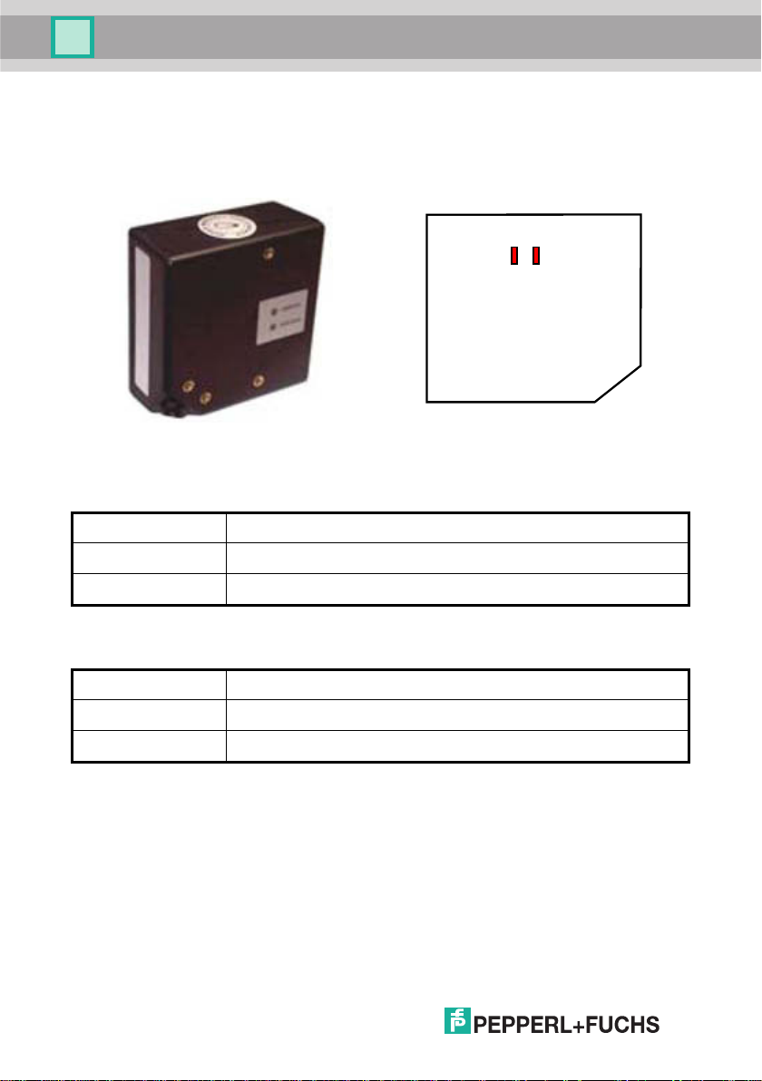
1.1 STATUS INDICATORS
The reader has two LED indicators signaling several operating conditions which are
described in the tables below.
Led2 Led1
VB8 Scanner
POWER ON / LED2 Meaning
ON Power supply ON
OFF
Power supply OFF
GOOD READ / LED1 Meaning
ON Good read (LED1 will remain ON until status changes)
OFF Miss read
POWER UP
DATA ENTRY
VB8 Scan Engine
Part No. 193603
2
Date of issue 12/2005
Page 7

VB8-305
Introduction
1.2 AVAILABLE MODELS
The VB8 reader is available in models that differ in regard to the following
characteristics:
• Barcode type
• Enclosure
The following models are therefore available:
Model1: VB8-305 = CCD Scanner for linear codes (10 to 30 V DC Power-supply)
•
•
Model2: VB8-305-5 V = CCD Scanner for linear codes (5 V DC Power-supply)
Part No. 193603
Date of issue 12/2005
3
Page 8
VB8-305
Installation
2 INSTALLATION
2.1
VB8 CCD SCANNER
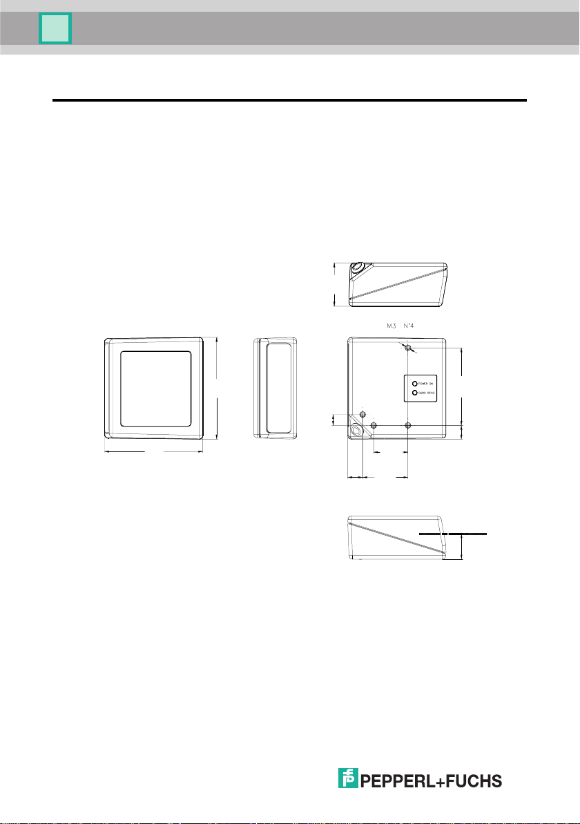
2.1.1 Mechanical Installation
The diagram below gives the overall dimensions of the reader and may be used for
its installation.
30.5
[1.20]
4
68.6
[2.70]
70.7
[2.78]
mm
[in.]
7.6
10.4
[0.41]
[0.30]
Figure 1 - Overall dimensions
[0.94]
31.6
[1.25]
54
[2.13]
24
9.5
[0.37]
Optical Axis
17.7
[0.70]
Part No. 193603
Date of issue 12/2005
Page 9
VB8-305
Installation
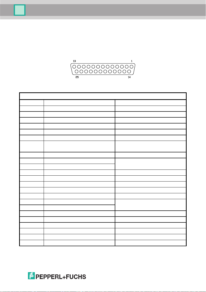
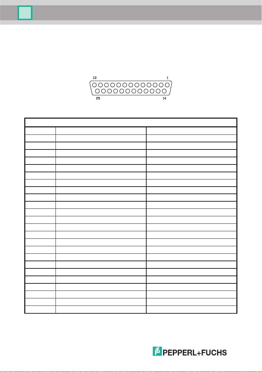
2.1.2 Electrical Connections VB8-305-5VDC
The VB8 Scanner is equipped with a 25-pin female D-Sub connector for connection
to the power supply and input/output signals. The details of the connector pins are
indicated in the following table:
Figure 2 - 25-pin female D-sub connector
25-pin Connector
1 Shield earth ground
2 TX transmit data
3 RX receive data
4 RTS request to send
5 CTS clear to send
6 nc not connected
7 SGND signal ground
8 EXT BEEPER beeper output signal
9 VCC+ +5 Vdc
10 nc not connected
11 OUT+
12 OUT13 VCC+ +5 Vdc
14 nc not connected
15 nc not connected
16 nc not connected
17 nc not connected
18 EXT TRIG+
19 EXT TRIG20 DATAIN_WAND
21 DATAOUT
22 OUT-
23 CLKIN
24 CLKOUT
25 GND power ground
see Figure 10
See Figures 6 to 9
Date of issue 12/2005 Part No. 193603
Table 1 - VB8 Scanner Pinout
5
Page 10
VB8-305
Installation
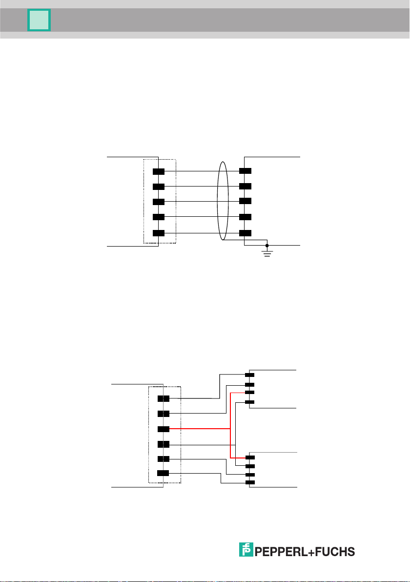
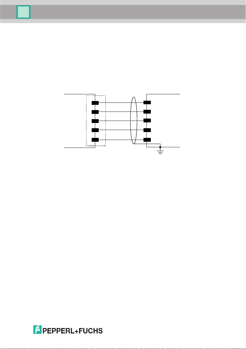
RS232 Interface
The VB8 Scanner can communicate with the Host using the RS232 signals
provided on the 25-pin connector. The pins are indicated in Table 1 and in the
following diagram:
It is always advisable to use shielded cables. The overall maximum cable length
must be less than 15 m (49.2 ft).
VB8 25-pin
2
TX
3
RX
4
RTS
CTS
5
7
SGND
Figure 3 - RS232 Interface connection to Host
Host
RXD
TXD
DCD
DTR
SGND
Earth
Ground
WEDGE Interface
The VB8 Scanner can communicate with the Host in a WEDGE Interface
(Keyboard Emulation) using the signals provided on the 25-pin connector. The pins
are indicated in Table 1 and in the following diagram:
VB8 25-pin
Figure 4 - Wedge Interface connection to Host (PC AT) and Keyboard
21
24
13
25
20
23
DATAOUT
CLKOUT
VCC+
GND
DATAIN
CLKIN
Host
DATA
CLK
VCC+
GND
Keyboard
VCC+
GND
DATA
CLK
Part No. 193603
Date of issue 12/2005
6
Page 11
VB8-305
Installation
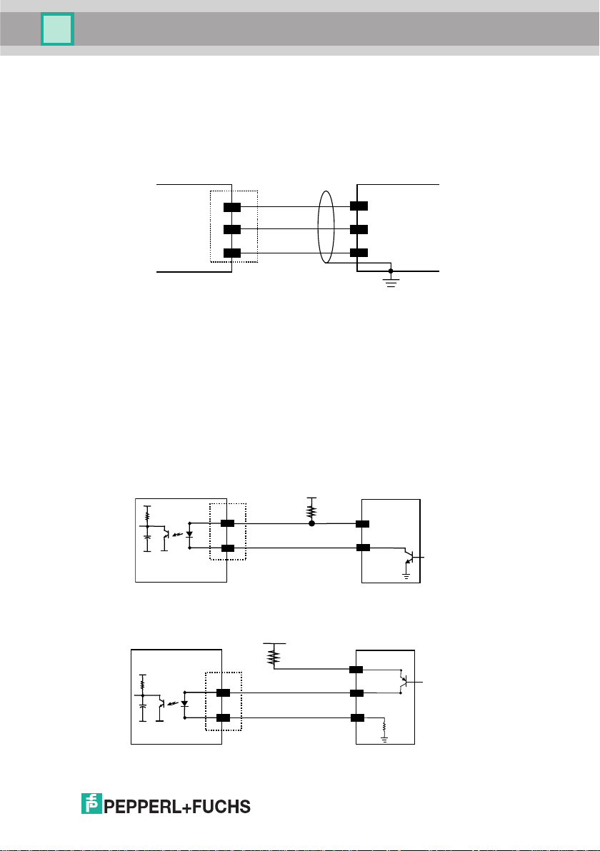
PEN Emulation Interface
The VB8 Scanner can communicate with the Host in a PEN Emulation Interface
using the signals provided on the 25-pin connector. The pins are indicated in Table 1
and in the following diagram:
VB8 25-pin
WAND
4
VCC+
5
GND
25
Figure 5 - RS232 Interface connection to Host
Host
DATA
VCC+
GND
Earth
Ground
It is always advisable to use shielded cables.
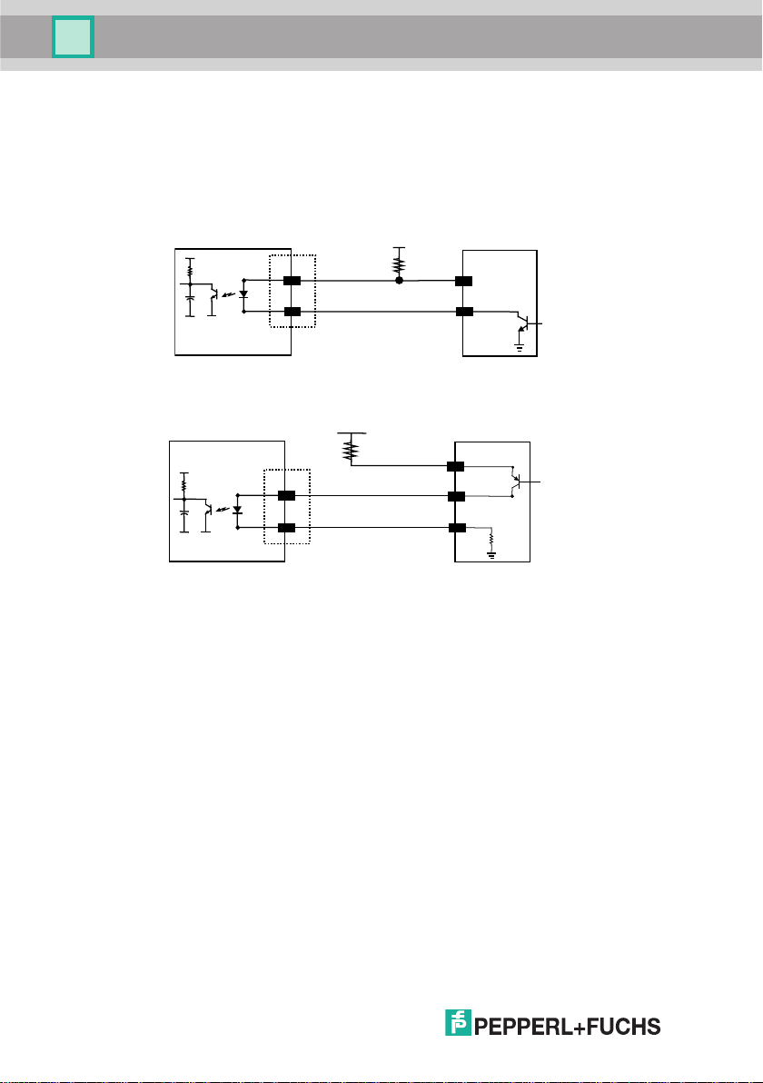
Inputs
There is an input available on the VB8 Scanner relative to the External Trigger.
The pins are indicated in Table 1. These inputs are optocoupled and can be driven
by both an NPN or PNP type command. The connections are indicated in the
following diagrams:
VB8
+ 5V
18
19
Vext
EXT TRIG+
EXT TRIG-
30 Vdc max.
EXTERNAL TRIGGER
V
Figure 6 - Input NPN command using external power
Vext
+ 5V
18
30 Vdc max.
EXT TRIG+
EXTERNAL TRIGGER
V
Signal
Signal
Date of issue 12/2005 Part No. 193603
19
EXT TRIG-
Ground
Figure 7 - Input PNP command using external power
7
Page 12
VB8-305
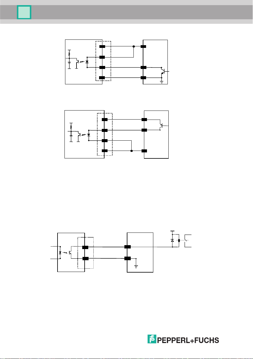
Installation
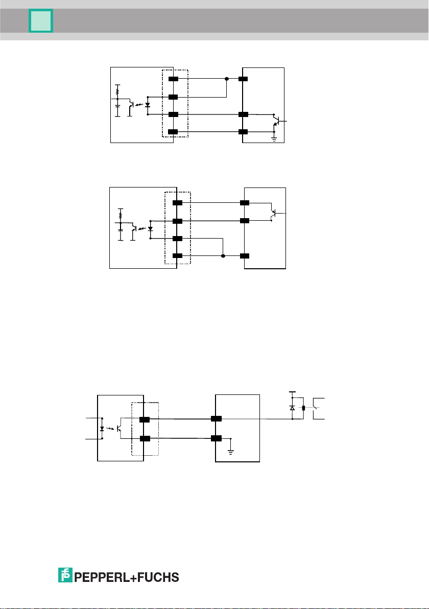
VB8
+ 5V
13
18
19
25
Vcc 5Vdc
EXT TRIG+
EXT TRIG-
GND
EXTERNAL TRIGGER
V
Ground
Signal
Figue 8 - Input NPN command using VB8 power
VB8
+ 5V
Vcc 5Vdc
13
18
EXT TRIG+
19
EXT TRIG-
25
GND
EXTERNAL TRIGGER
V
Signal
Ground
Figure 9 - Input PNP command using VB8 power
Outputs
There is an output available on the VB8 Scanner relative to the Good Read
event. The pins are indicated in Table 1. The connections are indicated in the
following diagram:
VB8
USER INTERFACE
Vext 40 Vdc max
8
11
OUT +
12
OUT -
Figure 10 - Output connection (Good Read). Example NPN
Part No. 193603
Date of issue 12/2005
Page 13
VB8-305
Installation
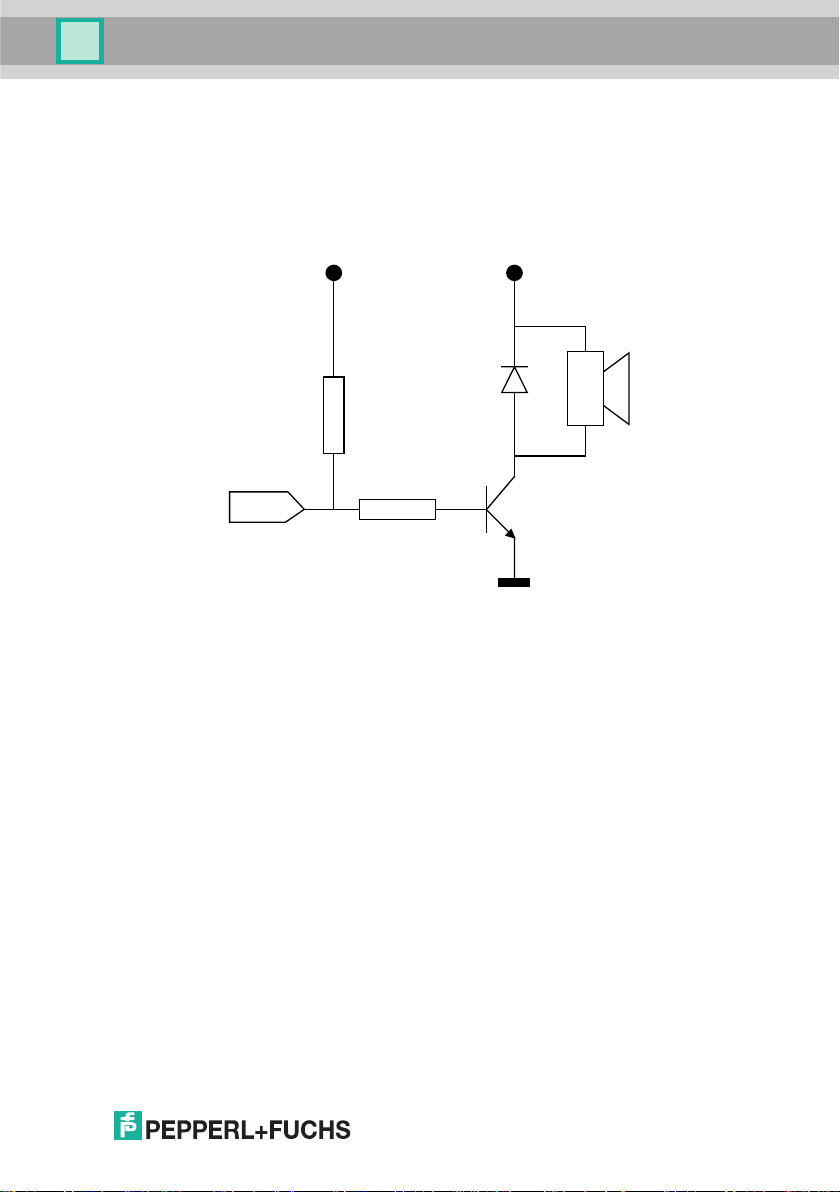
External Beeper Connection
A beeper output signal is provided on pin 8 so that an external piezoelectric buzzer
with internal oscillator can be connected for Good Read acoustic signaling. The
complete circuit to be built is shown in the schematic diagram below.
+5 Vdc (pin 13)+5 Vdc (pin 13)
+
BEEPER (pin 8)
D1 (1N4148)
R2 (10K)
Q1 (BC337)
R1 (1K)
GND (pin 25)
Figure 11 - VB8 Scanner Beeper Connection
BZ1 (see below)
The following list indicates several piezoelectric buzzers that can be used in the
circuitry above (part BZ1).
Manufacturer Type
MURATA PKB30SPC - 2001/3001
DIGISOUND F/TCW05
CITIZEN MEB-12C-5
BUJEON BS12-A
See chapter 3 for Beeper Control commands.
Date of issue 12/2005 Part No. 193603
9
Page 14
VB8-305
Installation
2.2 Electrical Connections VB8-305 (10 to 30 V DC)
The scanner cable is equipped with a 25-pin female D-sub connector for connection
with the power supply and input/output signals:
Figure 2 - 25-pin female D-sub connector
25-pin Connector
9, 13 VCC+ Power Supply Input Voltage +
25 GND
1 SHIELD
2, 21 TX
3, 20 RX
4 RTS
5 CTS
7
11 OUT +
10, 12, 22 OUT- Output -
18 EXT TRIG + External Trigger +
19 EXT TRIG - External Trigger -
6, 8, 14, 15, N.C.
16, 17, 23 N.C Not Connected
24 N.C. Not Connected
SGND Signal Ground
Power Supply Input Voltage -
Earth Ground
RS232 Transmit Data
RS232 Receive Data
RS232 Request To Send
RS232 Clear To Send
Output +
Not Connected
Part No. 193603
10
Table 1 - VB8 Scanner Pinout
Date of issue 12/2005
Page 15
VB8-305
Installation
RS232 Interface
The VB8 Scanner can communicate with the Host using the RS232 signals
provided on the 25-pin connector. The pins are indicated in Table 1 and in the
following diagram:
It is always advisable to use shielded cables. The overall maximum cable length
must be less than 15 m (49.2 ft).
VB8 25-pin
2
TX
3
RX
4
RTS
CTS
5
7
SGND
Figure 3 - RS232 Interface connection to Host
Host
RXD
TXD
DCD
DTR
SGND
Earth
Ground
Date of issue 12/2005 Part No. 193603
11
Page 16
VB8-305
Installation
Inputs
There is an input available on the VB8 Scanner relative to the External Trigger.
The pins are indicated in Table 1. These inputs are optocoupled and can be driven
by both an NPN or PNP type command. The connections are indicated in the
following diagrams:
VB8
+ 5V
18
19
Vext
EXT TRIG+
EXT TRIG-
30 Vdc max.
EXTERNAL TRIGGER
V
Figure 6 - Input NPN command using external power
Vext
+ 5V
18
19
30 Vdc max.
EXT TRIG+
EXT TRIG-
EXTERNAL TRIGGER
V
Ground
Signal
Signal
12
Figure 7 - Input PNP command using external power
Part No. 193603
Date of issue 12/2005
Page 17
VB8-305
Installation
VB8
+ 5V
13
18
19
25
Vcc 5Vdc
EXT TRIG+
EXT TRIG-
GND
EXTERNAL TRIGGER
V
Ground
Signal
Figue 8 - Input NPN command using VB8 power
VB8
+ 5V
Vcc 5Vdc
13
18
EXT TRIG+
19
EXT TRIG-
25
GND
EXTERNAL TRIGGER
V
Signal
Ground
Figure 9 - Input PNP command using VB8 power
Outputs
There is an output available on the VB8 Scanner relative to the Good Read
event. The pins are indicated in Table 1. The connections are indicated in the
following diagram:
VB8
USER INTERFACE
Vext 40 Vdc max
Date of issue 12/2005 Part No. 193603
11
OUT +
12
OUT -
Figure 10 - Output connection (Good Read). Example NPN
13
Page 18

VB8-305
Installation
14
Part No. 193603
Date of issue 12/2005
Page 19

VB8-305
Installation
Date of issue 12/2005 Part No. 193603
15
Page 20

VB8-305
Installation
2.3 POSITIONING
The VB8 scanner is able to decode barcode labels at a variety of angles,
however significant angular distortion may degrade reading performance.
When mounting the VB8 take into consideration these three ideal label position
angles: Pitch 0°, Skew 10° to 30° and Tilt 0°. Follow the suggestions for the best
orientation:
The Pitch angle is represented by the value P in Figure 23. Position the reader in
order to minimize the Pitch angle.
Figure 23 - Pitch Angle
The Skew angle is represented by the value S in Figure 24. Position the reader to
assure at least 10° for the Skew angle. This avoids direct light reflection.
P
16
S
Figure 24 - Skew angle
Part No. 193603
Date of issue 12/2005
Page 21

VB8-305
Installation
The Tilt angle is represented by the value T in Figure 25. Position the reader in order
to minimize the Tilt angle.
T
Figure 25 - Tilt angle
2.4 DeviationMirror OMH-VB8 ACCESSORY
The OMH-VB8 is an 80° deflection mirror that is mounted directly to the VB8
Scanner or Scan Engine.
Figure 26 - OMH-VB8
The overall dimensions are provided in the figure below and can be used for its
mounting.
Part No. 193603
Date of issue 12/2005
17
Page 22

VB8-305
Installation
104
[4.10]
4.5
[0.18]
84.5
[3.33]
5
0
°
[0.28]
10
[0.39]
20
[0.79]
70
[2.76]
20
[0.79]
10
[0.39]
7
Figure 27 - DeviationMirror OMH-VB8 Overall Dimensions
To fix a VB8-xxx Scanner to the OMH-VB8, use the 4 M 2.5x5 mm screws
supplied with the DeviationMirror Kit. Refer to the figure below.
[0.94]
24
18
Part No. 193603
Figure 28 – Fixing VB8 Scanner to DeviationMirror OMH-VB8
Date of issue 12/2005
Page 23

VB8-305
Installation
The 80° deflection mirror assures that the minimum skew angle is maintained to
avoid direct light reflection which can degrade reading performance.
5
0
°
80°
10°
Figure 30 – Maintaining minimum skew angle
VB8
Code Surface
Date of issue 12/2005 Part No. 193603
19
Page 24

VB8-305
Software Configuration Strings
3 SOFTWARE CONFIGURATION STRINGS
3.1 DEFAULT CONFIGURATION
RS232 INTERFACE
9600 baud, parity disabled, 8 data bits, 1 stop bit, handshaking disabled,
ACK/NACK from Host disabled, 100 ms RX timeout, FIFO enabled, inter-character
delay disabled
WEDGE INTERFACE
USA keyboard, caps lock off, delays disabled, control character emulation =
ctrl+shift+key;
PEN Emulation INTERFACE
interpret mode, conversion to code 39 disabled, output level normal, idle level
normal, minimum output pulse 600 µs, overflow medium
DATA FORMAT
Code identifier disabled, field adjustment disabled, code length TX disabled,
character replacement disabled, header = STX, terminator = CR LF
POWER SAVE
270 read/sec, sleep disabled, standby disabled
READING PARAMETERS
On-Line mode
DECODING PARAMETERS
Ink spread enabled, overflow control enabled, interdigit control enabled, Puzzle
Solver™ disabled, decoding safety = 1 read
Date of issue 12/2005 Part No. 193603
20
Page 25

VB8-305
Software Configuration Strings
CODE SELECTION
enabled codes
• Interleaved 2 of 5
Check digit transmitted, variable length code; 4-99 characters
• EAN8/EAN13UPC A/UPC B without ADD ON
Check digit transmitted, no conversions
• Code 39
variable length code; 1-99 characters
• Code 128
Check digit not transmitted, variable length code; 1-99 characters
disabled codes
EAN 128, ISBT128,Code 93, Codabar, pharmaceutical codes,
Codablock-A, Codablock-F Standard and EAN, MSI, Plessey, Telepen,
Delta IBM, Code 11, Code 16K, Code 49
Date of issue 12/2005 Part No. 193603
21
Page 26

VB8-305
Software Configuration Strings
3.2 VB8 CONFIGURATION
VB8 is factory set for RS232 Interface applications. The easiest way to configure
VB8 is by using the Configuration utility program installed from the CD
included with this manual. Otherwise you can configure the scanner using this
manual as follows:
To use this manual for configuration:
1) Connect your VB8 to a PC RS232 port according to the information in
chapter 2. Set the PC serial port to the VB8 default RS232 communication
parameters.
2) Using a Terminal Emulation Program send the Restore Default string to the
reader using the syntax described on the next page.
3) Send all the necessary command strings according to your application's
requirements.
The WEDGE or PEN Emulation interface selections must be sent
last since they will cause the reader to no longer accept RS232
CAUTION
If working with the Wedge or Pen emulation interfaces, it is possible to return to the
RS232 connection by reading the code given below:
communications.
For WEDGE or PEN Emulation Users
Return to RS232 Interface
i$1k
i$1k
i$1k
22
Date of issue 12/2005 Part No. 193603
Page 27

VB8-305
Software Configuration Strings
Command Syntax
The command syntax is given below with an example:
Command(s)
The new setting will be definitive (stored in FLASH EPROM)
Example:
Multiple command programming sequence:
$+
BK0
AC410132CD7
Baud rate = 19200
Serial On-Line operating mode
Enter configuration environment
Each configuration parameter setting removes the condition previously active for that
parameter.
The device buffer can contain about 400 characters. If your
programming string goes over this value, you must split it into separate
groups and send each group after a delay of at least 3 seconds to give
NOTE
the reader time to empty the buffer and interpret the commands.
Date of issue 12/2005 Part No. 193603
<CR>$-$+
CR
$-
Carriage return character (0D Hex.)
Exit and save new configuration
Matrix 2/5 3 bars: no check digit,
variable length code from 1 to 32 characters
23
Page 28

VB8-305
Software Configuration Strings
SERIAL CONFIGURATION STRINGS
DESCRIPTION STRING
ENTER/EXIT CONFIGURATION COMMANDS
Enter Configuration
Exit and Save Configuration
Restore Default
Transmit Software Release (not for PEN emulation)
These commands do not require $-.
DESCRIPTION STRING
INTERFACE SELECTION
RS232
WEDGE for IBM AT
for IBM Terminals: 31xx, 32xx, 34xx, 37xx; make-break keyboard
for IBM Terminals: 31xx, 32xx, 34xx, 37xx; make-only keyboard
typewriter
Keyboard Type for IBM Terminals 31xx,
32xx, 34xx, 37xx
advanced
for IBM XT
for IBM Terminal 3153
for IBM PC Notebook
for IBM SURE1
for IBM AT - ALT mode
for IBM PC Notebook - ALT mode
for Wyse Terminal - ANSI Keyboard
for Wyse Terminal - PC Keyboard
for Wyse Terminal - ASCII Keyboard
for Wyse Terminal - VT220 style Keyboard
for Digital Terminals VT2xx/3xx/4xx
for Apple ADB Bus
PEN EMULATION
$+
$$+$*<CR>
$+$!<CR>
CP0
CP500
CP501
CP502
FK0
FK1
CP503
CP504
CP505
CP506
CP507
CP508
CP509
CP510
CP511
CP514
CP512
CP513
CP6
Date of issue 12/2005 Part No. 193603
24
Page 29

VB8-305
Software Configuration Strings
RS232
WEDGE
CD0
CD1
CD2
CD3
CD4
CD5
CD6
CD7
CD8
CC0
CC1
CC2
CA0
CA1
CA2
CB0
CB1
CE0
CE1
CE2
CE3
CF0
CF3
EC0
EC1
CK00 - CK99
CL00 - CL99
FJ7
FJ4
FJ2
FJ3
FJ1
FJ6
FJ5
FJ0
DESCRIPTION STRING
Baud rate 150
300
600
1200
2400
4800
9600
19200
38400
Parity none
even
odd
Data bits 7
8
9
Stop bits 1
2
Handshaking disable
RTS/CTS
XON/XOFF
RTS always On
ACK/NACK Protocol disable
enable
FIFO disable
enable
Inter-character delay (ms)
RX Timeout (100 ms)
DESCRIPTION STRING
Keyboard nationality Belgian
English
French
German
Italian
Spanish
Swedish
USA
Date of issue 12/2005 Part No. 193603
25
Page 30

VB8-305
Software Configuration Strings
DESCRIPTION STRING
WEDGE (continued)
Caps Lock caps Lock ON
caps Lock OFF
Num Lock Toggle Num Lock
Num Lock Unchanged
Delays
Inter-Character (ms)
Inter-Code (s)
Control Character Emulation
Ctrl + Shift + Key
Ctrl + Key
FE1
FE0
FL1
FL0
CK00 - CK99
FG00 - FG99
FO0
FO1
PEN
DESCRIPTION STRING
Operating mode
Minimum output pulse
interpret (does not require
transparent (does not require
200µs
400µs
600µs
800µs
1 ms
1.2 ms
Conversion to Code 39 disable conversion to Code 39
enable conversion to Code 39
Output level normal
inverted
Idle level normal
inverted
Overflow narrow overflow
medium overflow
wide overflow
Inter-Block delay (100 ms)
$+
or $-)
$+
or $-)
$]
$[
DG0
DG1
DG2
DG3
DG4
DG5
DA0
DA1
DD0
DD1
DE0
DE1
DH0
DH1
DH2
CK00-CK99
Date of issue 12/2005 Part No. 193603
26
Page 31

VB8-305
Software Configuration Strings
NOT FOR PEN EMULATION INTERFACES
DATA FORMAT
DESCRIPTION STRING
Code Identifier disable
DL standard
AIM standard
Custom
Custom Code Identifier
Headers no header
one character
two characters
three characters
four characters
five characters
six characters
seven characters
eight characters
Terminators no terminator
one character
two characters
three characters
four characters
five characters
six characters
seven characters
eight characters
EB0
EB1
EB2
EB3
EH
abc
EA00
EA01x
EA02xx
EA03
xxx
xxxx
xxxxx
xxxxxx
xxxxxxx
xxxxxxxx
EA10
EA11x
xxx
xxxx
xxxxx
xxxxxx
xxxxxxx
xxxxxxxx
EA04
EA05
EA06
EA07
EA08
EA12xx
EA13
EA14
EA15
EA16
EA17
EA18
a = ASCII character.
b, c, x = HEX values representing an ASCII character.
a = ASCII character of the DL STANDARD Code Identifier from the table in
Appendix A.
00
b = Hex value of the first Custom Code Identifier character from
FF
= disable Code Identifier
= Hex value of the second Custom Code Identifier character from 00 to FE;
c
FF
= disable second character of Custom Code Identifier
x = Hex value from
00
to FE
to FE;
Date of issue 12/2005 Part No. 193603
27
Page 32

VB8-305
Software Configuration Strings
DATA FORMAT (continued)
DESCRIPTION STRING
Code Length Tx not transmitted
transmitted in variable-digit format
transmitted in fixed 4-digit format
Field Adjustment disable
right addition
left addition
right deletion
Field Adjustment Character
Character Replacement disable character replacement
first character replacement
second character replacement
third character replacement
a = ASCII character.
d = a number from the Hex/Numeric Table
e, f, g = HEX values representing an ASCII character
a = ASCII character of the DL STANDARD Code Identifier from the table in
Appendix A.
d = a number in the range
e = Hex value from
f = Hex value of the character to be replaced from
g
= Hex value of the new character to insert from 00 to FE
FF
= replace with no new character (remove character)
DESCRIPTION STRING
Read Rate 67 reads per sec.
135 reads per sec.
270 reads per sec.
Sleep State disable
enable
Enter Sleep Timeout (100 ms)
Standby enable
disable
NOT FOR PEN EMULATION INTERFACES
left deletion
01-32
from the Hex/Numeric Table
00
to FE
00
to FE
POWER SAVE
EE0
EE1
EE2
EF0
EFa0d
EFa1d
EFa2d
EFa3d
EGe
EO0
EO1
afg
EO2
afg
EO3
afg
BT0
BT1
BT2
BQ0
BQ1
BR00-BR99
BM0
BM1
Date of issue 12/2005 Part No. 193603
28
Page 33

VB8-305
Software Configuration Strings
DESCRIPTION STRING
READING PARAMETERS
Operating Modes serial on-line
See page 41 for details
on-line
automatic
test Mode disable
enable
Beeper Intensity very low intensity
low intensity
medium intensity
high intensity
Beeper Tone Tone 1
Tone 2
Tone 3
Tone 4
Beeper Type monotone
bitonal
Beeper Length long
short
BK0
BK1
BK3
#DStat0<CR>
#DStat1<CR>
BG0
BG1
BG2
BG3
BH0
BH1
BH2
BH3
BJ0
BJ1
BI0
BI1
DESCRIPTION STRING
DECODING PARAMETERS
Ink-Spread disable
enable
Overflow Control disable
enable
Interdigit Control disable
enable
Puzzle SolverTM disable
enable
Decoding Safety one read
two reads
three reads
four reads
CODE SELECTION
DESCRIPTION STRING
DISABLE ALL FAMILY CODES
EAN/UPC Disable EAN/UPC family
EAN 8/EAN 13/UPC A/UPC E without ADD ON
with ADD ON
with and without ADD ON
EAN 8/EAN 13 without ADD ON
with ADD ON 2 ONLY
with ADD ON 5 ONLY
with ADD ON 2 AND 5
Date of issue 12/2005 Part No. 193603
AX0
AX1
AW1
AW0
AV0
AV1
AU0
AU1
ED0
ED1
ED2
ED3
AZ0
AA0
AA1
AA5
AA8
AA3
AAK
AAL
AA6
29
Page 34

VB8-305
Software Configuration Strings
DESCRIPTION STRING
UPC A/UPC E without ADD ON
with ADD ON 2 ONLY
with ADD ON 5 ONLY
with ADD ON 2 AND 5
EAN 8 check digit transmission disable
enable
EAN 13 check digit transmission disable
enable
UPC A check digit transmission disable
enable
UPC E check digit transmission disable
enable
Conversions UPC E to UPC A
UPC E to EAN 13
UPC A to EAN 13
EAN 8 to EAN 13
Code 39 disable Code 39 family
Standard no check digit control
check digit control and transmission
check digit control without transmission
Full ASCII no check digit control
check digit control and transmission
check digit control without transmission
CIP 39
Code 32
code length
ISBN Conversion codes
CODE SELECTION (continued)
enable ISBN
enable ISSN
enable ISBN and ISSN
disable ISBN and ISSN
AA4
AAM
AAN
AA7
AAG0
AAG1
AAH0
AAH1
AAI0
AAI1
AAJ0
AAJ1
AAA
AAB
AAC
AAD
AP1
AP2
AP3
AP0
AB0
AB11
AB12
AB13
AB21
AB22
AB23
AB3
AB4
AB*
xxxx
xxxx = ASCII numbers that define the code length where:
• First 2 digits = minimum acceptable code length.
• Second 2 digits = maximum acceptable code length.
The minimum code length must always be less than or equal to the maximum.
The maximum code length for all codes is 99 characters.
Examples:
0132 = variable length from 1 to 32 digits in the code.
1010 = 10 digit code length only.
Date of issue 12/2005 Part No. 193603
30
Page 35

VB8-305
Software Configuration Strings
DESCRIPTION STRING
CODE SELECTION (continued)
2/5 disable Code 2/5 family
Interleaved 2/5 no check digit control
check digit control and transmission
check digit control without transmission
Normal 2/5 5 bars no check digit control
check digit control and transmission
check digit control without transmission
Industrial 2/5 (IATA) no check digit control
check digit control and transmission
check digit control without transmission
Matrix 2/5 3 bars no check digit control
check digit control and transmission
check digit control without transmission
CIP/HR
Codabar disable Codabar family
Standard no start/stop character equality control
nor transmission
no start/stop character equality control
but transmission
start/stop character equality control
but no transmission
start/stop character equality control
and transmission
ABC Codabar no start/stop character equality control
but transmission
Codabar ABC forced concatenation
code length
start/stop character case in transmission lower case
upper case
xxxx = ASCII numbers that define the code length where:
• First 2 digits = minimum acceptable code length.
• Second 2 digits = maximum acceptable code length.
The minimum code length must always be less than or equal to the maximum.
The maximum code length for all codes is 99 characters:
EXAMPLES:
0132 = variable length from 1 to 32 digits in the code.
1010 = 10 digit code length only.
Date of issue 12/2005 Part No. 193603
AC0
AC11
xxxx
xxxx
xxxx
xxxx
xxxx
xxxx
xxxx
xxxx
xxxx
xxxx
xxxx
xxxx
AC5
AD0
xxxx
ADA0
ADA1
AC12
AC13
AC21
AC22
AC23
AC31
AC32
AC33
AC41
AC42
AC43
AD111
AD112
AD121
AD122
AD212
AD232
AD*
31
Page 36

VB8-305
Software Configuration Strings
DESCRIPTION STRING
CODE SELECTION (continued)
Code 128 disable Code 128 family
enable Code 128
control without transmission of check digit
enable EAN 128
control without transmission of check digit
add GS before Code disable
enable
ISBT 128 enable ISBT 128
enable all concatenations
disable all concatenations
Code 93 disable Code 93 family
enable Code 93
control without transmission of check digit
Codablock-A disable
enable
Codablock-F disable the family
enable Standard
enable EAN
MSI disable the family
no check
MOD10 no tx
MOD10 with tx
MOD11-MOD10 no tx
MOD11-MOD10 with tx
MOD10-MOD10 no tx
MOD10-MOD10 with tx
Plessey disable the family
Standard no check
Standard check - with tx
Standard check - no tx
Anker no check
Anker check - with tx
Anker check - no tx
Telepen disable the family
Numeric no check
Numeric check - with tx
Numeric check - no tx
Alpha no check
Alpha check - with tx
Alpha check - no tx
Delta IBM disable the family
no check
Type 1 check
Type 2 check
AI0
AI11
AI21
EQ0
EQ1
AI31
=&FNC3=<=>103d1
=&FNC3=<=>103d0
AK0
AK1
AO0
AO1
AN0
AN1
AN2
AE0
AE1
AE2
AE3
AE4
AE5
AE6
AE7
AF0
AF11
AF12
AF13
AF21
AF22
AF23
AL0
AL11
AL12
AL13
AL21
AL22
AL23
AH0
AH1
AH2
AH3
Date of issue 12/2005 Part No. 193603
32
Page 37

VB8-305
Software Configuration Strings
DESCRIPTION STRING
CODE SELECTION (continued)
Code 11 disable the family
no check
Type C with tx
Type C no tx
Type K with tx
Type K no tx
Type C and K with tx
Type C and K no tx
Code 16K disable
enable
Code 49 disable
enable
PDF417 disable
enable
AG0
AG1
AG21
AG22
AG31
AG32
AG41
AG42
AJ0
AJ1
AM0
AM1
AR0
AR1
Date of issue 12/2005 Part No. 193603
33
Page 38

y
y
y
VB8-305
Preferences
4 REFERENCES
4.1 RS232 PARAMETERS
4.1.1 Handshaking
Hardware handshaking: (RTS/CTS)
The RTS line is activated by the decoder before transmitting a character.
Transmission is possible only if the CTS line (controlled by the Host) is active.
Signals at
EIA levels
RTS
TX
Transmitted data Transmitted data
CTS
Host bus
Figure 31 - RTS/CTS handshaking
Software handshaking: (XON/XOFF)
During transmission, if the Host sends the XOFF character (13 Hex), the decoder
interrupts the transmission with a maximum delay of one character and only resumes
when the XON character (11 Hex) is received.
Transmitted dataTransmitted data
TX
RX
XONXOFF
Host bus
Host read
Figure 32 - XON/XOFF handshaking
34
Date of issue 12/2005 Part No. 193603
Page 39

VB8-305
Preferences
4.1.2 ACK/NACK from Host Protocol
This parameter sets a transmission protocol in which the Host responds to the reader
after every code transmitted. The Host sends an ACK character (06 HEX) in the case
of good reception or the NACK character (15 HEX) requesting re-transmission, in the
case of bad reception.
data
VB8
cable
ACK or NACK
Figure 33 - ACK/NACK enabled
Host
4.1.3 FIFO
This parameter determines whether data (barcodes) are buffered on a First In First
Out basis allowing faster data collection in certain cases for example when using
slow baud rates and/or hardware handshaking.
If the FIFO buffering is enabled, codes are collected and sent out on the serial line in
the order of acquisition. About 800 characters can be collected (buffer full), after
which the reader signals an error and discards any further codes until the
transmission is restored.
If the FIFO buffering is disabled, each code must be transmitted before another one
can be read.
4.1.4 RX Timeout
When the RS232 interface is selected, the Host can be used to configure the device
by sending it command strings (see chapter 3).
This parameter can be used to automatically end data reception from the Host after
the specified period of time.
If no character is received from the Host, after the timeout expires, any incomplete
string (any string not terminated by <CR>) is flushed from the device buffer.
Date of issue 12/2005 Part No. 193603
35
Page 40

VB8-305
Preferences
4.2 PEN PARAMETERS
4.2.1 Minimum Output Pulse
This parameter sets the duration of the output pulse corresponding to the narrowest
element in the barcode. In this way the code resolution is controlled by the signal
sent to the decoder, independently of the physical resolution of the code read.
µ
The shortest pulse (200
therefore a shorter transfer speed to the decoder (for decoders able to work on high
resolution codes). Likewise, longer pulses correspond to low resolution code
emulation and therefore a longer transfer time to the decoder.
s) corresponds to a high resolution code emulation and
4.2.2 Overflow
This parameter generates a white space before the first bar and after the last bar of
the code. The selections are as follows:
narrow = space 10 times the minimum output pulse.
medium = space 20 times the minimum output pulse.
wide = space 30 times the minimum output pulse.
36
Date of issue 12/2005 Part No. 193603
Page 41

VB8-305
Preferences
4.2.3 Output and Idle Levels
The following state diagrams describe the different output and idle level combinations
for Pen Emulation:
OUTPUT: Normal
IDLE: Normal
OUTPUT: Normal
IDLE: Inverted
idle
idle
space
barcode output
space
barcode output
bar
bar
black
white
black
white
OUTPUT: Inverted
IDLE: Normal
OUTPUT: Inverted
IDLE: Inverted
idle
idle
space
space
barcode output
barcode output
bar
bar
white
black
white
black
Figure 34 - Output and Idle Levels
4.2.4 Inter-Block Delay
For the PEN Emulation interface, data are sent to the Host in fixed size blocks of 20
characters each. The inter-block delay parameter allows setting a delay between
each block sent to the Host.
Date of issue 12/2005 Part No. 193603
37
Page 42

VB8-305
Preferences
4.3 DATA FORMAT
4.3.1 Header/Terminator Selection
The header/terminator selection is not effected by the reading of the restore default
code. In fact, header and terminator default values depend on the interface selection:
RS232: no header, terminator CR-LF
WEDGE: no header, terminator ENTER
These default values are always
interface selection code, see chapter 3.
For the WEDGE interface, the following extended keyboard values can also be
configured:
EXTENDED KEYBOARD TO HEX CONVERSION TABLE
HEX KEY KEY KEY KEY
83
84
85
86
87
88
89
8A
8B
8C
8D
8E
8F
90
91
92
93
94
95
96
97
98
99
9A
9B
For all readers using Wedge interface, all values from
IBM AT
IBM 3153
APPLE ADB
ENTER ENTER FIELD EXIT RETURN
TAB TAB TAB TAB
F1 F1 F1 F1
F2 F2 F2 F2
F3 F3 F3 F3
F4 F4 F4 F4
F5 F5 F5 F5
F6 F6 F6 F6
F7 F7 F7 F7
F8 F8 F8 F8
F9 F9 F9 F9
F10 F10 F10 F10
F11 ESC F11 F11
F12 BACKSPACE F12 F12
HOME HOME ENTER F13
END END RESET F14
PG UP PG UP INSERT F15
PG DOWN PG DOWN DELETE F16
↑
↓
←
→
ESC ESC ESC
CTRL (Right) CTRL (Right) CTRL (Right)
Euro Space Space Space
restored through the reading of RS232 or WEDGE
IBM XT IBM 31xx, 32xx,
34xx, 37xx
↑
↓
←
→
FIELD - UP
FIELD + DOWN
ENTER (Paddle) LEFT
PRINT RIGHT
9C
to FE send the Space character.
Wyse
Digital
Date of issue 12/2005 Part No. 193603
38
Page 43

VB8-305
Preferences
SET CUSTOM EXTENDED HEADER/TERMINATOR KEYS
The extended Header/Terminator keys for Wedge Interface
customized by defining them through a simple keyboard setting procedure.
For example, the Numeric Keypad keys can be set for use as Headers or
Terminators by substituting the default extended keys using this procedure.
The type of computer or terminal must be selected before activating the keyboard
setting command.
Press and release a key to set it.
Some characters may require more than one key pressed simultaneously during
normal use (refer to the manual of your PC or terminal for keyboard use). The exact
sequence must be indicated to the reader in this case pressing and releasing the
different keys.
Example:
If one has to press the "Shift" and "4" keys simultaneously on the keyboard to
transmit the character "$" to the video, to set the "$", press and release "Shift" then
press and release "4".
Each pressed and released key must generate an acoustic signal on the reader,
otherwise repress the key. Never press more than one key at the same time, even if
this corresponds to the normal use of your keyboard.
Press "Backspace" to correct a wrong key entry. In this case the reader emits 2
beeps.
Note: "CAPS LOCK" and "NUM LOCK" must be off before starting the keyboard
setting procedure. "SHIFT" must be repressed for each character and cannot
be substituted by "CAPS LOCK".
users can be
Date of issue 12/2005 Part No. 193603
39
Page 44

VB8-305
Preferences
Set Custom Extended Header/Terminator Keys
Enter the code above.
•
If the first 4 KEYS (Shift, Alt, Ctrl, and Backspace) are not available on
your keyboard, you can only substitute them with keys not used, or
substitute them with each other.
•
Keys 5 to 28 must be defined
Press the desired keys in the following order:
The reader signals the end of the procedure with 2 beeps indicating the keys
have been registered.
CUSTOM EXTENDED KEYBOARD SETTING TABLE
$+FB1$-
Order HEX KEY
01
02
03
04
05
06
07
08
09
10
11
12
13
14
15
16
17
18
19
20
21
22
23
24
25
26
27
28
-
-
-
83
84
85
86
87
88
89
8A
8B
8C
8D
8E
8F
90
91
92
93
94
95
96
97
98
99
9A
Custom
Shift
Alt
Ctrl
Backspace
40
Date of issue 12/2005 Part No. 193603
Page 45

VB8-305
Preferences
4.4 POWER SAVE
4.4.1 Sleep State
µ
This mode allows the
consumption. This command is only valid when On-Line is selected.
Before entering Sleep mode, the following are verified:
•
no commands coming from Host
•
no data being transmitted to Host
•
Enter Sleep Timeout ended
To exit Sleep mode press the trigger.
Enabling the Sleep state implements Standby mode for CCD devices.
P in the reader to enter a “Sleep” state for minimum power
4.4.2 Enter Sleep Timeout
For readers that have the Sleep state enabled, this timeout determines when the
reader will enter this state.
4.4.3 Standby
If this command is enabled, part of the CCD circuitry shuts down (Standby), in order
to optimize low power consumption when not reading. When the trigger is pressed
this circuitry powers up. This mode causes a minor delay of about 100 ms before the
reader is ready.
4.5 READING PARAMETERS
4.5.1 Operating Modes
This group of parameters allows setting different reading modes:
•
ON-LINE: the VB8 reader is connected to an external Presence Sensor
using EXT TRIG+ and EXT TRIG- inputs. During the active phase of the
presence sensor, the VB8 tries to acquire and correctly decode the code. If the
operation is successful, the barcode characters are transmitted on the serial
interface in the format defined by the current configuration. Otherwise a No
Read message is sent: it is fixed as the CAN symbol;
Date of issue 12/2005 Part No. 193603
41
Page 46

VB8-305
Preferences
•
AUTOMATIC: the VB8 reader does not require connections with external
presence sensors in this operating mode. In this mode the illuminator is always
ON and VB8 is continuously scanning. The reading phase is enabled when a
barcode enters the reading zone of the camera and is terminated after a fixed
number of scans without a code. The next reading phase will begin when a code
enters the reading zone again.
The number of scans without a code is an optimized value for the CCD camera
in order to improve code identification in the reading zone. Code transmission
occurs as in the other operating modes but in case of No Read condition there is
no transmission on the serial port.
•
SERIAL ON-LINE: the reading phase starts when the Serial Start Character is
received on the serial interface and ends when the code is read or a Serial Stop
Character is received. If decoding is correct, the data is transmitted on the serial
port as defined by the configuration. Otherwise a No Read message is sent: it is
fixed as the CAN symbol. The Start and Stop characters are also fixed:
Serial START: STX
Serial STOP: ETX
•
TEST MODE: test mode allows verifying the reader position and the associated
reading features. The code is continuously read when in this mode. After
400 ms, the values relative to an internal counter and the decoded code are
displayed and transmitted on the serial interface.
The counter reports a statistical calculation which consists of a good reading
percentage of the total acquisitions.
The following message could be displayed:
Counter value Code
090% 12345ABC
If the CCD reader cannot decode a label, the following message will be
displayed:
0%.
Only one barcode label must be read for each reading cycle.
Since Test Mode is basically a diagnostic mode, it can only be
enabled at run time and not saved to a non-volatile memory.
For the same reason, this operating mode must be disabled
NOTE
only via RS232 interface by selecting another Operating Mode
command, if you want to restore the previous state of the
reader.
42
Date of issue 12/2005 Part No. 193603
Page 47

VB8-305
Preferences
4.5.2 Reads per Cycle
In general, a reading cycle corresponds to the Phase ON / Phase OFF times of a
device.
The resulting effects of this parameter on code reading depend on other related
configuration conditions. Here are the definitions of Phase ON and Phase OFF times.
When one read per cycle is selected, the device decodes only one code during the
Phase ON period and immediately turns to the Phase OFF
another code when the next Phase ON time occurs.
In multiple reads per cycle, the Phase ON period is extended so that the device
can continue decoding codes until an OFF event occurs.
. It is only possible to read
4.6 DECODING PARAMETERS
These parameters are intended to enhance the decoding capability
of the reader for particular applications. Used incorrectly, they can
degrade the reading performance or increase the possibility of a
CAUTION
decoding error.
4.6.1 Ink-Spread
The ink-spread parameter allows the decoding of codes which are not perfectly
printed because the page texture tends to absorb the ink.
4.6.2 Overflow Control
The overflow control parameter can be disabled when decoding codes printed on
small surfaces, which don’t allow the use of an overflow space.
This command does not effect code families 2/5, Code 128 and Code 93.
This command is forced (enabled) when PDF417 codes are enabled.
4.6.3 Interdigit Control
The interdigit control parameter verifies the interdigit spacing for code families
Code 39 and Codabar.
Date of issue 12/2005 Part No. 193603
43
Page 48

VB8-305
Technical Features
5 TECHNICAL FEATURES
ELECTRICAL FEATURES
Supply voltage
Model1: 10 - 30VDC / Model2: 5 VDC ± 5%
Power consumption 1.5 W
Interfaces RS232, Wedge, PEN Emulation
LED Indicators
Power ON / Power OFF / Good Read / Miss
OPTICAL FEATURES
Sensor CCD solid state
Max read rate 270 read/sec
Reading field See diagrams on page 45
Max. resolution 0.076 mm (3 mils)
ENVIRONMENTAL FEATURES
Working temperature 0° to +40 °C / 32° to 104 °F
Storage temperature -20° to +70 °C / 4° to 158 °F
READING FEATURES
Readable codes:
Pharmaceutical codes
Codablock-F Std
Codablock-F EAN
MECHANICAL FEATURES
Dimensions (LxWxH) 60.5 x 63 x 27 mm / 2.38 x 2.48 x 1.06 in
Read
EAN/UPC
Code 39
2/5 family
Codabar
Code 128
EAN 128
ISBT 128
Code 93
Telepen
MSI
Plessey
Delta IBM
Codablock-A
Code 11
Code 16K
Code 49
Date of issue 12/2005 Part No. 193603
44
Page 49

VB8-305
Technical Features
READING DIAGRAMS
0 20 40 60 80 100 120 140 160 180 200 220 240 260 280 300 320
160
140
120
100
80
0.20 mm
60
40
20
0
-20
-40
-60
-80
-100
-120
0.13 mm
-140
(5 mils)
-160
Reading Diagram VB8-xxx (code 39)
0.20 mm
(8 mils)
0.30 mm
(12 mils)
0.50 mm
(20 mils)
Date of issue 12/2005 Part No. 193603
45
Page 50

VB8-305
Technical Features
mm
0 20 40 60 80 100 120 140 160 180 200 220 240 260 280 300 32 0
160
140
120
100
80
0.20 mm
60
40
20
0
-20
-40
-60
-80
-100
-120
0.13 mm
-140
(5 mils)
-160
0.20 mm
(8 mils)
0.30 mm
(12 mils)
Reading Diagram VB8-xxx (code 39)
0.50 mm
(20 mils)
46
Date of issue 12/2005 Part No. 193603
Page 51

VB8-305
Code Identifier Table
A CODE IDENTIFIER TABLE
CODE IDENTIFIER TABLE
CODE AIM STANDARD Custom
2/5 interleaved ] I y N
2/5 industrial ] X y P
2/5 normal 5 bars ] S y O
2/5 matrix 3 bars ] X y Q
EAN 8 ] E 4 A
EAN 13 ] E 0 B
UPC A ] X y C
UPC E ] X y D
EAN 8 with 2 ADD ON ] E 5 J
EAN 8 with 5 ADD ON ] E 6 K
EAN 13 with 2 ADD ON ] E 1 L
EAN 13 with 5 ADD ON ] E 2 M
UPC A with 2 ADD ON ] X y F
UPC A with 5 ADD ON ] X y G
UPC E with 2 ADD ON ] X y H
UPC E with 5 ADD ON ] X y I
Code 39 ] A y V
Code 39 Full ASCII ] A y W
CODABAR ] F y R
ABC CODABAR ] X y S
Code 128 ] C y T
EAN 128 ] C y k
ISBT 128 ] C4 f
Code 93 ] G y U
CIP/39 ] X y Y
CIP/HR ] X y e
Code 32 ] X y X
Codablock-A ] O 6 n
Codablock-F Std ] O 4 l
Codablock-F EAN ] O 5 m
MSI ] M y Z
Plessey Standard ] P 0 a
Plessey Anker ] P 1 o
Telepen ] X 0 d
Part No. 193603
Delta IBM ] X 0 c
Code 11 ] H y b
Code 16K ] K 0 p
Code 49 ] T y q
PDF417 ] L 0 r
Date of issue 12/2005
P+F STANDARD
47
Page 52

VB8-305
Hex/Numeric Table
B HEX/NUMERIC TABLE
CHARACTER TO HEX CONVERSION TABLE
char hex char hex char hex
NUL
SOH
STX
ETX
EOT
ENQ
ACK
BEL
BS
HT
LF
VT
FF
CR
SO
SI
DLE
DC1
DC2
DC3
DC4
NAK
SYN
ETB
CAN
EM
SUB
ESC
FS
GS
RS
US
SPACE
!
"
#
$
%
&
'
(
)
00
01
02
03
04
05
06
07
08
09
0A
0B
0C
0D
0E
0F
10
11
12
13
14
15
16
17
18
19
1A
1B
1C
1D
1E
1F
20
21
22
23
24
25
26
27
28
29
*
+
,
.
/
0
1
2
3
4
5
6
7
8
9
:
;
<
=
>
?
@
A
B
C
D
E
F
G
H
I
J
K
L
M
N
O
P
Q
R
S
T
2A
2B
2C
2D
2E
2F
30
31
32
33
34
35
36
37
38
39
3A
3B
3C
3D
3E
3F
40
41
42
43
44
45
46
47
48
49
4A
4B
4C
4D
4E
4F
50
51
52
53
54
U
V
W
X
Y
Z
[
\
]
^
_
`
a
b
c
d
e
f
g
h
i
j
k
l
m
n
o
p
q
r
s
t
u
v
w
x
y
z
{
|
}
~
DEL
55
56
57
58
59
5A
5B
5C
5D
5E
5F
60
61
62
63
64
65
66
67
68
69
6A
6B
6C
6D
6E
6F
70
71
72
73
74
75
76
77
78
79
7A
7B
7C
7D
7E
7F
Part No. 193603
Date of issue 12/2005
48
Page 53

VB8-305
Part No. 193603
Date of issue 12/2005
With regard to the supply of products, the current issue of the following document is applicable:
The General Terms of Delivery for Products and Services of the Electrical Industry, published by
the Central Association of the "Elektrotechnik und Elektroindustrie (ZVEI) e.V.
in their most recent version as well as the supplementary clause: "Extended reservation of title".
Page 54

FACTORY AUTOMATION – SENSING YOUR NEEDS
For half a century, Pepperl+Fuchs have been continually providing new stimuli for the world of automation. The company
is also setting standards in quality and innovative technology. We develop, produce and distribute electronic sensors and
interface modules on a global scale. By means of our world-wide presence and our high flexibility in production and customer service we are able to individually offer complete solutions – right where you need us. We know what we are talking
about – Pepperl+Fuchs have established a good reputation in supplying the world’s biggest offer of industrial sensor
technology for a large scale of applications. Our signals move the world.
Twinsburg
Worldwide Headquarters
Pepperl+Fuchs GmbH
68307 Mannheim · Germany
Tel. +49 621 776-0
E-Mail: info@de.pepperl-fuchs.com
USA Headquarters
Pepperl+Fuchs Inc.
Twinsburg, Ohio 44087 · USA
Tel. +1 330 4253555
E-Mail: sales@us.pepperl-fuchs.com
Asia Pacific Headquarters
Pepperl+Fuchs Pte Ltd. · P+F Building
Singapore 139942
Tel. +65 6779-9091
E-Mail: sales@sg.pepperl-fuchs.com
Mannheim
Singapur
www.pepperl-fuchs.com
Subject to reasonable modifications due to technical advances
Copyright PEPPERL+FUCHS • Printed in Germany
TDOCT-0965AENG
Part No. 193603
12/2005
 Loading...