

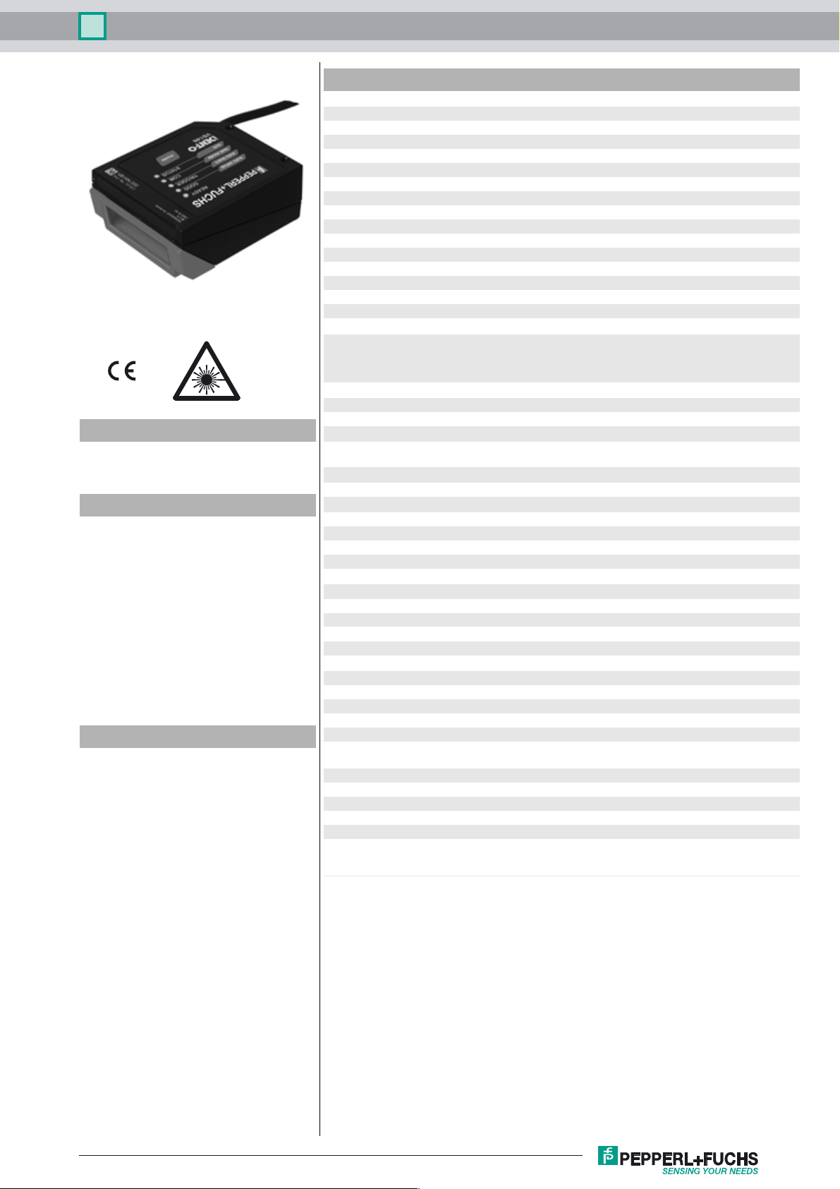
Barcode scanner VB14N-300
Technical Data
General specifications
Light source laser diode
Light type modulated visible red light
Laser nominal ratings
Note LASER LIGHT , DO NOT STARE INTO BEAM
Laser class 2
Wave length 650 nm
Beam divergence < 1.5 mrad
Pulse length 1.3 ms
Repetition rate 200 Hz
Model Number
VB14N-300
Barcode scanner
Features
• Line scanner
• Simple operation via function keys:
test mode, code teaching and code
optimization
• Code reconstructor
• Connect up to 32 scanners
• Sturdy aluminum housing
• Two serial interfaces RS 232 / RS 485
• Engine control (On/Off) possible
• Degree of protection IP65
Function
The VB14N-300 is a line scanner for 1-D barcodes. With its high-performance optics and
code reconstruction, the scanner offers a
high level of reliability in reading difficult-todetect 1-D barcodes.
A function key and several LEDs on the barcode scanner provide support when parameterizing, teaching in barcodes, and testing. In
live operation, the LEDs provide information
about the relevant read status.
A high-speed connection can be established
between up to 32 devices. This connection
enables data to be recorded in a quicker and
more efficient manner, without the need for
an additional external multiplexer.
The corresponding PC software makes
parameterization simple.
max. pulse energy 1.19 µJ
Scan rate 500 ... 800 s
Read distance 40 ... 300 mm
Angle of divergence 50 °
Optical face front or on side (with deviation mirror)
Resolution 0.2 mm ( 8 mils )
Indicators/operating means
Operation indicator LED blue: Power on, LED green: Ready to read (READY), LED
Electrical specifications
Operating voltage UB10 ... 30 V DC
Power consumption P
Interface
Interface type serial , RS-232 and RS-485 up to 115.2 kBit/s
Input 1
Input type External triggering
Output
Signal output 2, programmable, optocoupled
Switching voltage max. 40 V DC
Switching current max. 40 mA
Voltage drop Ud1 V at load current ≤ 10 mA
Ambient conditions
Ambient temperature 0 ... 45 °C (32 ... 113 °F)
Storage temperature -20 ... 70 °C (-4 ... 158 °F)
Relative humidity 90 % , noncondensing
Shock resistance IEC 68-2-27 Test EA 30G; 11 ms; 3 impacts on each axis
Vibration resistance IEC 68-2-6 Test FC 1.5 mm ; 10 ... 55 Hz ; 2 hours on each axis
Mechanical specifications
Degree of protection IP65
Connection 1 m cable with 25-pin Sub-D connector
Material
Housing aluminum
Mass 330 g
Compliance with standards and directives
Directive conformity EMC Directive 2004/108/EC
Standard conformity
Noise immunity EN 61000-6-2:2005
Emitted interference EN 55022
Degree of protection EN 60529
Laser class IEC 60825-1:2007 Complies with 21 CFR 1040.10 and 1040.11
green: Read successfully (GOOD), LED yellow: External trigger
signal pending (TRIGGER), LED yellow: Communication active
(COM), LED red: "no read" (STATUS)
max. 3 W
0
ID-NET™ up to 1 Mbit/s
except for deviations pursuant to Laser Notice No. 50, dated
June 24, 2007
-1
Release Date: 2014-11-07 10:26 Date of issue: 2014-11-07 206845_eng.xml
Refer to “General Notes Relating to Pepperl+Fuchs Product Information”.
1
VB14N-300Barcode scanner
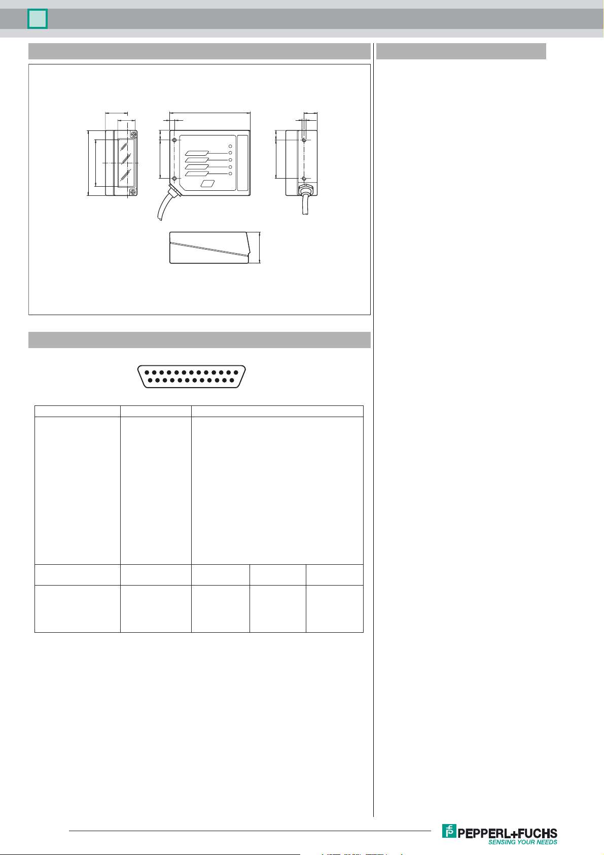
Dimensions
23.3
14
46
68
Electrical connection
Accessories
CBX100
Connector box for barcode scanner
OM-VB14N
84
4
10
40
1
auto setup
auto learn
test mode
exit
mode
READY
GOOD
TRIGGER
STATUS
COM
13
10
40
33
14.7
M4
oscillating mirror for the VB14N barcode
scanner series
DM-VB14N-90
Deviation mirror for barcode scanner series VB14
DM-VB14N-102
Deviation mirror for barcode scanner series VB14
CBX500-KIT-B6
PROFIBUS Connector box for barcode
scanner
CBX500-KIT-B17
PROFINET Connector box for barcode
scanner
CBX500-KIT-B19-IP54
EtherNet/IP Connector box for barcode
scanner
CBX500-KIT-B19-IP65
EtherNet/IP Connector box for barcode
scanner
Other suitable accessories can be found at
25-pin D-sub connector pinout
14
25
Pin Name Function
9, 13 +UB Power supply input voltage +
25 GND Power supply input voltage 1 GND Chassis Cable shield connected to chassis
18 IN TRG + (A) External Trigger A +
19 IN TRG - (B) External Trigger B 6 IN 2 + (A) Input 2 A +
10 IN 2 - (B) Input 2 B 8 OUT 1 + Output 1 +
22 OUT 1 - Output 1 11 OUT 2 + Output 2 +
12 OUT 2 - Output 2 20 RX RS232 Auxiliary RS232
21 TX RS232 Auxiliary RS232
23 ID + High speed internal network ID-NET +
24 ID - High speed internal network ID-NET 14, 15, 16, 17 NC Not connected
Pin RS232 RS485 RS485
full-duplex half-duplex
2 TX TX + RTX +
3 Main RX RX +
4 interface RTS TX - RTX 5 signals CTS RX 7 SGND SGND SGND
Release Date: 2014-11-07 10:26 Date of issue: 2014-11-07 206845_eng.xml
Refer to “General Notes Relating to Pepperl+Fuchs Product Information”.
2
 Loading...