

Page 1
MANUAL
BARCODE SCANNER
VB14A
FACTORY AUTOMATION
Page 2

VB14A
With regard to the supply of products, the current issue of the following document is applicable:
The General Terms of Delivery for Products and Services of the Electrical Industry, published by
the Central Association of the "Elektrotechnik und Elektroindustrie (ZVEI) e.V.
in their most recent version as well as the supplementary clause: "Extended reservation of title".
Date of issue 12/2005 Part No. 190311
Page 3

Barcode Scanner VB14A
S
P
Contents
1 REFERENCES . . . . . . . . . . . . . . . . . . . . . . . . . . . . . . . . . . . . . . . . . . . . .5
1.1 Conventions . . . . . . . . . . . . . . . . . . . . . . . . . . . . . . . . . . . . . . . . . . . . . . . . . . . . . 5
1.2 Reference Documentation . . . . . . . . . . . . . . . . . . . . . . . . . . . . . . . . . . . . . . . . . . 5
1.3 Service, Support and Warranty . . . . . . . . . . . . . . . . . . . . . . . . . . . . . . . . . . . . . . 5
2 SAFETY REGULATIONS. . . . . . . . . . . . . . . . . . . . . . . . . . . . . . . . . . . . .6
2.1 Laser Safety . . . . . . . . . . . . . . . . . . . . . . . . . . . . . . . . . . . . . . . . . . . . . . . . . . . . . 6
2.2 Standard Regulations. . . . . . . . . . . . . . . . . . . . . . . . . . . . . . . . . . . . . . . . . . . . . . 6
2.3 Power Supply . . . . . . . . . . . . . . . . . . . . . . . . . . . . . . . . . . . . . . . . . . . . . . . . . . . . 7
3 GENERAL VIEW . . . . . . . . . . . . . . . . . . . . . . . . . . . . . . . . . . . . . . . . . . .8
4 GUIDE TO INSTALLATION . . . . . . . . . . . . . . . . . . . . . . . . . . . . . . . . . . .9
5 INTRODUCTION. . . . . . . . . . . . . . . . . . . . . . . . . . . . . . . . . . . . . . . . . . .10
5.1 Product description . . . . . . . . . . . . . . . . . . . . . . . . . . . . . . . . . . . . . . . . . . . . . . 10
5.1.1 Indicators . . . . . . . . . . . . . . . . . . . . . . . . . . . . . . . . . . . . . . . . . . . . . . . . . . . . . . . 11
5.2 Model Description. . . . . . . . . . . . . . . . . . . . . . . . . . . . . . . . . . . . . . . . . . . . . . . . 11
5.3 Accessory Installation . . . . . . . . . . . . . . . . . . . . . . . . . . . . . . . . . . . . . . . . . . . . 12
6 INSTALLATION . . . . . . . . . . . . . . . . . . . . . . . . . . . . . . . . . . . . . . . . . . .13
6.1 Package Contents. . . . . . . . . . . . . . . . . . . . . . . . . . . . . . . . . . . . . . . . . . . . . . . . 13
6.1.1 Mechanical Installation . . . . . . . . . . . . . . . . . . . . . . . . . . . . . . . . . . . . . . . . . . . . . 14
6.1.2 Mounting VB14A. . . . . . . . . . . . . . . . . . . . . . . . . . . . . . . . . . . . . . . . . . . . . . . . . . 15
6.1.3 Mounting the Scanner with Deflection Mirror . . . . . . . . . . . . . . . . . . . . . . . . . . . . 16
6.2 Electrical Connections . . . . . . . . . . . . . . . . . . . . . . . . . . . . . . . . . . . . . . . . . . . . 17
6.2.1 Power supply . . . . . . . . . . . . . . . . . . . . . . . . . . . . . . . . . . . . . . . . . . . . . . . . . . . . 18
6.2.2 Main Serial Interface. . . . . . . . . . . . . . . . . . . . . . . . . . . . . . . . . . . . . . . . . . . . . . . 18
6.2.3 Auxiliary RS232 Interface . . . . . . . . . . . . . . . . . . . . . . . . . . . . . . . . . . . . . . . . . . . 21
6.2.4 Inputs . . . . . . . . . . . . . . . . . . . . . . . . . . . . . . . . . . . . . . . . . . . . . . . . . . . . . . . . . . 22
6.2.5 Outputs . . . . . . . . . . . . . . . . . . . . . . . . . . . . . . . . . . . . . . . . . . . . . . . . . . . . . . . . . 24
6.3 User Interface . . . . . . . . . . . . . . . . . . . . . . . . . . . . . . . . . . . . . . . . . . . . . . . . . . . 25
6.4 Positioning . . . . . . . . . . . . . . . . . . . . . . . . . . . . . . . . . . . . . . . . . . . . . . . . . . . . . 26
6.5 Typical Layouts. . . . . . . . . . . . . . . . . . . . . . . . . . . . . . . . . . . . . . . . . . . . . . . . . . 27
6.5.1 Point-to-Point . . . . . . . . . . . . . . . . . . . . . . . . . . . . . . . . . . . . . . . . . . . . . . . . . . . . 27
6.5.2 Pass-Through . . . . . . . . . . . . . . . . . . . . . . . . . . . . . . . . . . . . . . . . . . . . . . . . . . . . 28
6.5.3 RS232 Master/Slave. . . . . . . . . . . . . . . . . . . . . . . . . . . . . . . . . . . . . . . . . . . . . . . 29
6.5.4 RS485 Master/Slave. . . . . . . . . . . . . . . . . . . . . . . . . . . . . . . . . . . . . . . . . . . . . . . 30
7 READING FEATURES . . . . . . . . . . . . . . . . . . . . . . . . . . . . . . . . . . . . . .31
7.1 Advanced Code Builder (ACB) . . . . . . . . . . . . . . . . . . . . . . . . . . . . . . . . . . . . . 31
7.1.1 Important ACB Reading Conditions . . . . . . . . . . . . . . . . . . . . . . . . . . . . . . . . . . . 32
7.1.2 Tilt Angle Improvement with ACB . . . . . . . . . . . . . . . . . . . . . . . . . . . . . . . . . . . . . 33
7.2 Linear Code Reading . . . . . . . . . . . . . . . . . . . . . . . . . . . . . . . . . . . . . . . . . . . . . 33
7.2.1 Step-Ladder mode . . . . . . . . . . . . . . . . . . . . . . . . . . . . . . . . . . . . . . . . . . . . . . . . 33
7.2.2 Picket-Fence mode. . . . . . . . . . . . . . . . . . . . . . . . . . . . . . . . . . . . . . . . . . . . . . . . 34
7.3 Performance . . . . . . . . . . . . . . . . . . . . . . . . . . . . . . . . . . . . . . . . . . . . . . . . . . . . 35
7.3.1 Raster . . . . . . . . . . . . . . . . . . . . . . . . . . . . . . . . . . . . . . . . . . . . . . . . . . . . . . . . . . 36
7.4 Reading Diagrams . . . . . . . . . . . . . . . . . . . . . . . . . . . . . . . . . . . . . . . . . . . . . . . 37
Date of issue 12/2005
ubject to reasonable modifications due to technical advances. Copyright Pepperl+Fuchs, Printed in Germany
epperl+Fuchs Group • Tel.: Germany (06 21) 7 76-0 • USA (330) 4 25 35 55 • Singapore 7 79 90 91 • Internet http://www.pepperl-fuchs.com
3
Page 4

Barcode Scanner VB14A
S
P
Contents
8 MAINTENANCE . . . . . . . . . . . . . . . . . . . . . . . . . . . . . . . . . . . . . . . . . . .44
8.1 Cleaning . . . . . . . . . . . . . . . . . . . . . . . . . . . . . . . . . . . . . . . . . . . . . . . . . . . . . . . 44
9 TROUBLESHOOTING . . . . . . . . . . . . . . . . . . . . . . . . . . . . . . . . . . . . . .45
9.1 General Guidelines . . . . . . . . . . . . . . . . . . . . . . . . . . . . . . . . . . . . . . . . . . . . . . 45
10 TECHNICAL FEATURES. . . . . . . . . . . . . . . . . . . . . . . . . . . . . . . . . . . .48
11 Glossary . . . . . . . . . . . . . . . . . . . . . . . . . . . . . . . . . . . . . . . . . . . . . . . . 50
Declaration of conformity
declares that the
VB14A-XXXX Laser Scanner
and all its models
are in conformity with the requirements of the European Council Directives listed
below:
89/336/EEC EMC Directivee92/31/EEC, 93/68/EECemendamenti successivi
and further amendments
On the approximation of the laws of Member States relating to electromagnetic
compatibility and product safety.
This declaration is based upon compliance of the products to the following standards:
EN 55022, August 1994:LIMITS AND METHODS OF MEASUREMENTS OF RADIO
DISTURBANCE CHARACTERISTICS OF INFORMATION TECHNOLOGY
EQUIPMENT (ITE)
EN 61000-6-2, October 2001:ELECTROMAGNETIC COMPATIBILITY (EMC).
PART 6-2: GENERIC STANDARDS - IMMUNITY FOR INDUSTRIAL
ENVIRONMENTS
Lippo di Calderara, 14/09/2004
Ruggero Cacioppo
Quality Assurance Supervisor
A corresponding declaration of conformity can be requested from the
manufacturer.
Information
Pepperl+Fuchs GmbH in D-68301 Mannheim possesses a certified quality assurance
system in accordance with ISO 9001.
ISO9001
Date of issue 12/2005
ubject to reasonable modifications due to technical advances. Copyright Pepperl+Fuchs, Printed in Germany
4
epperl+Fuchs Group • Tel.: Germany (06 21) 7 76-0 • USA (330) 4 25 35 55 • Singapore 7 79 90 91 • Internet http://www.pepperl-fuchs.com
Page 5

Barcode Scanner VB14A
S
P
REFERENCES
1 REFERENCES
1.1 Conventions
This manual uses the following conventions:
• "User" or "Operator" refers to anyone using a VB14A.
• "Device" refers to the VB14A.
• "You" refers to the System Administrator or Technical Support person using this
manual to install, mount, operate, maintain or troubleshoot a VB14A.
1.2 Reference Documentation
The documentation related to the VB14A is listed below:
• C-BOX 100 Installation Manual
• C-BOX 300 Installation Manual
• VisoSetup Help On Line
1.3 Service, Support and Warranty
Pepperl+Fuchs provides several services as well as technical support through its
website. Log on to www.pepperl-fuchs.com ' Factory automation for further
information.
Date of issue 12/2005
ubject to reasonable modifications due to technical advances. Copyright Pepperl+Fuchs, Printed in Germany
epperl+Fuchs Group • Tel.: Germany (06 21) 7 76-0 • USA (330) 4 25 35 55 • Singapore 7 79 90 91 • Internet http://www.pepperl-fuchs.com
5
Page 6
Barcode Scanner VB14A
S
P
SAFETY REGULATIONS
2 SAFETY REGULATIONS
2.1 Laser Safety
The following information is provided to comply with the rules imposed by
international authorities and refers to the correct use of the VB14A scanner.
2.2 Standard Regulations
This scanner utilizes a low-power laser diode. Although staring directly at the laser
beam momentarily causes no known biological damage, avoid staring at the beam as
one would with any very strong light source, such as the sun. Avoid that the laser
beam hits the eye of an observer, even through reflective surfaces such as mirrors,
etc.
This product conforms to the applicable requirements of both EN 60825-1 and CDRH
21 CFR 1040 at the date of manufacture. The scanner is classified as a Class 2 laser
product according to EN 60825-1 regulations and as a Class II laser product
according to CDRH regulations.
There is a safety device which allows the laser to be switched on only if the motor is
rotating above the threshold for its correct scanning speed.
The motor and laser beam can be switched off through a software command (see also
the VisoSetup Help On Line).
Use of controls or adjustments or performance of procedures other than
those specified herein may result in exposure to hazardous visible laser
light.
Warning
The laser light is visible to the human eye and is emitted from the window on the front
of the scanner (figure 3.1 (7)).
General notes
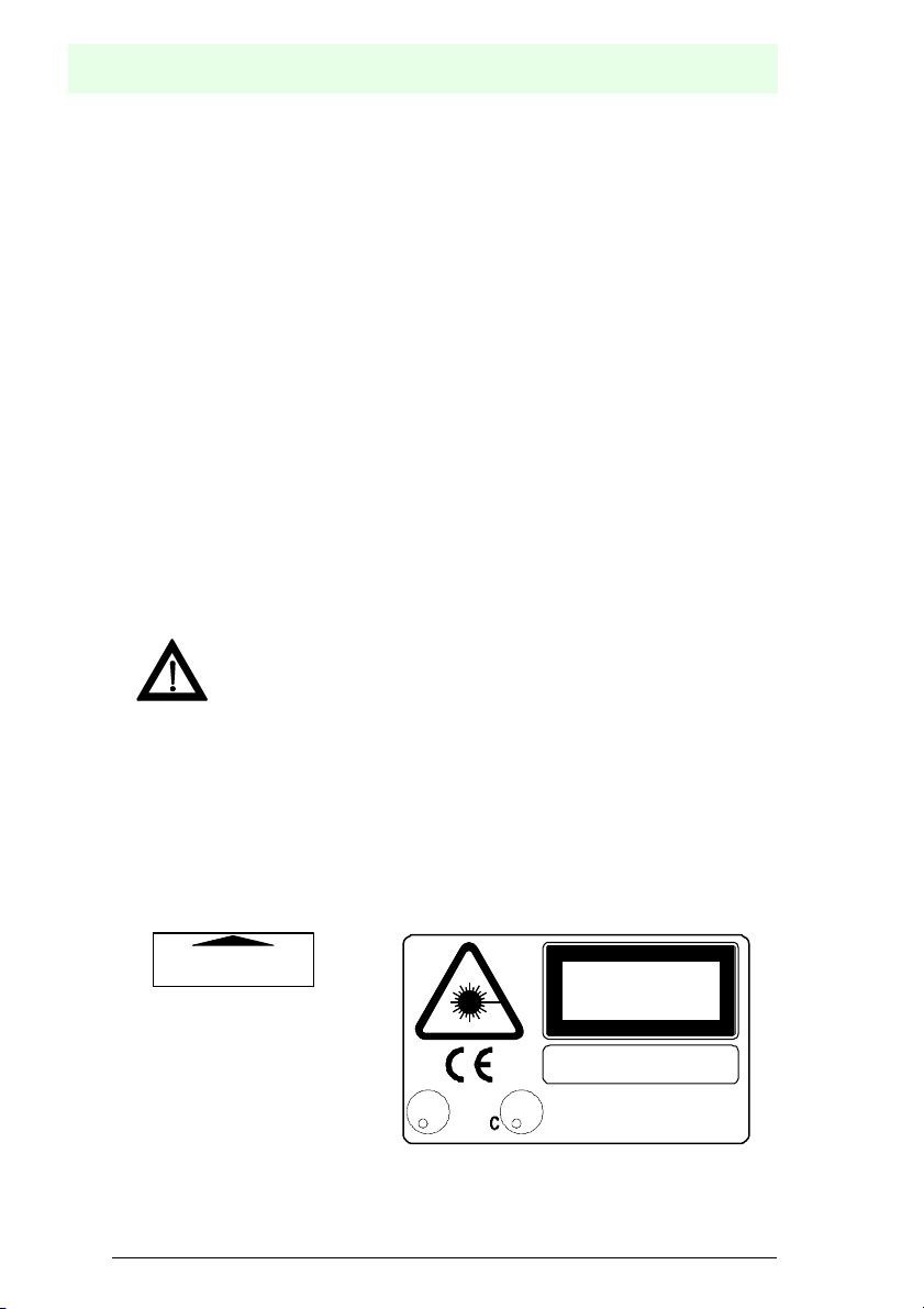
Warning labels indicating exposure to laser light and the device classification are
applied onto the body of the scanner (figure 3.1).
Warning and device class labels
AVOID EXPOSURE-LASER LIGHT IS
EMITTED FROM THIS APERTURE
LISTED
ACCESSORY
U
45 AF
L
R R
i.T.E.
ubject to reasonable modifications due to technical advances. Copyright Pepperl+Fuchs, Printed in Germany
6
epperl+Fuchs Group • Tel.: Germany (06 21) 7 76-0 • USA (330) 4 25 35 55 • Singapore 7 79 90 91 • Internet http://www.pepperl-fuchs.com
This product conforms to the applicable
requirements of 21CFR1040 at the
U
L
date of manuffacture.
LASER LIGHT
DO NOT STARE INTO BEAM
CLASS 2 LASER PRODUCT
MAX. OUTPUT RADIATION 1 mW
EMITTED WAVE LENGTH 630-680 NM
CAUTION - LASER LIGHT WHEN OPEN
AVOID EXPOSURE TO BEAM
TO IEC 825-1 (1993)
Date of issue 12/2005
Page 7
Barcode Scanner VB14A
S
P
SAFETY REGULATIONS
Disconnect the power supply when opening the device during maintenance or installation to avoid exposure to hazardous laser light.
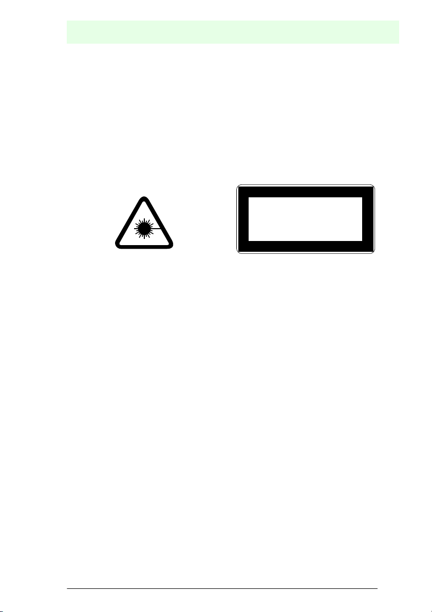
The laser diode used in this device is classified as a class 3B laser product according
to EN 60825-1 regulations and as a Class IIIb product according to CDRH regulations.
As it is not possible to apply a classification label on the laser diode used in this
device, the following label is reproduced on the right.
Any violation of the optic parts in particular can cause radiation up to the maximum
level of the laser diode (7 mW at 630 to 680 nm).
Laser diode class label
LASER LIGHT
AVOID EXPOSURE TO BEAM
CLASS 3B LASER PRODUCT
MAX. OUTPUT RADIATION 7 nW
EMITTED WAVE LENGTH 6 30~680 nm
TO IEC 825-1 (1993)
2.3 Power Supply
-This product is intended to be installed by Qualified Personnel only.
- All Models:
This accessory device is intended to be supplied by a UL Listed or CSA Certified
Power Unit with "Class 2" or LPS power source which supplies power directly to the
scanner via the 25-pin connector.
Date of issue 12/2005
ubject to reasonable modifications due to technical advances. Copyright Pepperl+Fuchs, Printed in Germany
epperl+Fuchs Group • Tel.: Germany (06 21) 7 76-0 • USA (330) 4 25 35 55 • Singapore 7 79 90 91 • Internet http://www.pepperl-fuchs.com
7
Page 8
Barcode Scanner VB14A
S
P
GENERAL VIEW
3 GENERAL VIEW
5
4
3
2
1
VB14A
6
8
7
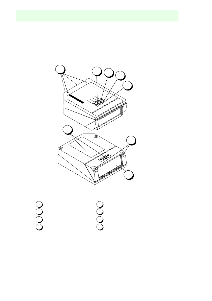
1
Power ON/Data TX LED Mounting holes
2
External Trigger LED Warning and device Class
3
Good read LED Laser beam output window
4
Laser ON LED Accessory mounting screws
5
6
7
8
Figure 3.1 VB14A General view
Date of issue 12/2005
ubject to reasonable modifications due to technical advances. Copyright Pepperl+Fuchs, Printed in Germany
8
epperl+Fuchs Group • Tel.: Germany (06 21) 7 76-0 • USA (330) 4 25 35 55 • Singapore 7 79 90 91 • Internet http://www.pepperl-fuchs.com
Page 9

Barcode Scanner VB14A
S
P
GUIDE TO INSTALLATION
4 GUIDE TO INSTALLATION
The following can be used as a checklist to verify all of the steps necessary for
complete installation of the VB14A scanner.
1. Read all information in the section "Safety Precautions" at the beginning of this
manual.
2. Correctly mount the reader using the bracket provided according to the
information see Section 6.1.2
3. Position the reader at the correct reading distance according to your model as
shown see Section 6.4
4. Make electrical connections to your VB14A scanner by either:
a) Connecting the test cable to the VB14A scanner as described in figure 6.17
b) Providing correct and complete system cabling according to the signals
necessary for the layout of your application.
• Layout: Point-to-point, RS485 Master/Slave, RS232 Master/Slave, See sub-para-
graphs under see section 6.5 for reference.
• "Cabling: Power, Main Serial Interface, Auxiliary Interface (RS232), Inputs, Out-
puts, etc. For further details, see all sub-paragraphs under section 6.2
5. Configure the VB14A scanner by installing and running the VisoSetup
configuration program from the CD- ROM provided. The main steps are:
•"Select the codes to be read
•"Set-up the communication parameters
•"Define data formatting parameters
•"Fine tune your VB14A scanner using the Test Mode as described in VisoSetup.
Specific parameter details are available in the Help On Line. See also the Guide To
Rapid Configuration link.
6. Exit the configuration program and run your application.
The installation is now complete.
Date of issue 12/2005
ubject to reasonable modifications due to technical advances. Copyright Pepperl+Fuchs, Printed in Germany
epperl+Fuchs Group • Tel.: Germany (06 21) 7 76-0 • USA (330) 4 25 35 55 • Singapore 7 79 90 91 • Internet http://www.pepperl-fuchs.com
9
Page 10

Barcode Scanner VB14A
S
P
INTRODUCTION
5 INTRODUCTION
5.1 Product description
The VB14A laser scanner satisfies the most advanced needs of a wide range of
users. It has been developed focusing on the realistic requirements of its target
market. The outstanding result is an extremely compact, cost-effective and easy to
use industrial scanner.
Standard Application Program A standard application program is factory-
Custom Application Programs If the Standard Application Program doesn't
Some of the main features of VB14A are listed below:
• ACB (Advanced Code Builder)
• small dimensions and light weight
• software programmable scanning speed (500 to 1000 scans/sec)
• linear and raster versions
• completely configurable via serial interface (VisoSetup)
• 2 serial communication interfaces
• supply voltage from 10 to 30 Vdc
• reads all popular codes
• test mode to verify the reading features and exact positioning of the scanner without the need for external tools
• programmable in 4 different operating modes to suit the most various barcode
reading system requirements
• code verifier
The VB14A uses a solid state laser diode as a light source; the light emitted has a
wavelength between 630 and 680 nm. Refer to the section "Safety precautions" at the
beginning of this manual for information on laser safety.
The protection class of the enclosure is IP65, the reader is therefore suitable for
industrial environments where high protection against harsh external conditions is
required.
loaded onto the VB14A. This program controls
barcode reading, serial port interfacing, data
formatting and many other operating and control parameters.
It is completely configurable from a host computer through the VisoSetup utility program
provided on CD-ROM with the scanner, or
through ESC sequences via the serial interface.
meet your requirements, please contact your
local P+F distributor.
Date of issue 12/2005
ubject to reasonable modifications due to technical advances. Copyright Pepperl+Fuchs, Printed in Germany
10
epperl+Fuchs Group • Tel.: Germany (06 21) 7 76-0 • USA (330) 4 25 35 55 • Singapore 7 79 90 91 • Internet http://www.pepperl-fuchs.com
Page 11
Barcode Scanner VB14A
S
P
INTRODUCTION
5.1.1 Indicators
The four LEDs on the side of the scanner indicate the following:
PWR/TXD LED (red) (figure 3.1 (1)) indicates the reader is connected to
GOOD READ LED (red) (figure 3.1 (3)) is used to signal the possibility of a
EXT TRIG LED (yellow) (figure 3.1 (2)) indicates external trigger activity.
LASER ON LASER ONLED (green) (figure 3.1 (4)) indicates laser ON
The screw holes on the body of the reader are for mechanical fixture
(see section 3.1 (5)).
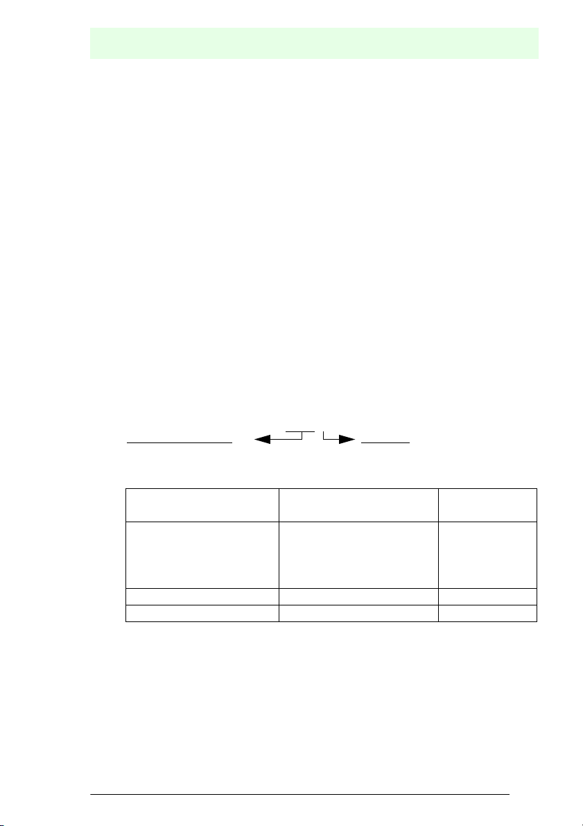
5.2 Model Description
The VB14A scanner is available in versions that differ in regard to the following
parameters:
• Resolution
• Linear or raster models
• Performance
The following models are therefore available:
Max. Reading Distance R = Raster
the power supply or, when blinking (green), data transmission.
successful barcode reading.
Refer to see section 6.2.4.
state.
VB14A--
The following tables display each version's reading performance.
Version Max Code Resolution Speed
Pin mm (mils) scans/s
VB14A-600 / VB14A-600-R 0.35 (14) 600 to 1000
VB14A-440 / VB14A-440-R 0.25 (10) 600 to 1000
VB14A-340 / VB14A-340-R 0.20 (8) 600 to 1000
VB14A-310 / VB14A-310-R 0.20 (8) 800 to 1000
VB14A-100 / VB14A-100-R 0.12 (5) 800 to 1000
VB14A-300 / VB14A-300-R 0.20 (8) 500 to 800
Date of issue 12/2005
ubject to reasonable modifications due to technical advances. Copyright Pepperl+Fuchs, Printed in Germany
epperl+Fuchs Group • Tel.: Germany (06 21) 7 76-0 • USA (330) 4 25 35 55 • Singapore 7 79 90 91 • Internet http://www.pepperl-fuchs.com
11
Page 12
Barcode Scanner VB14A
S
P
INTRODUCTION
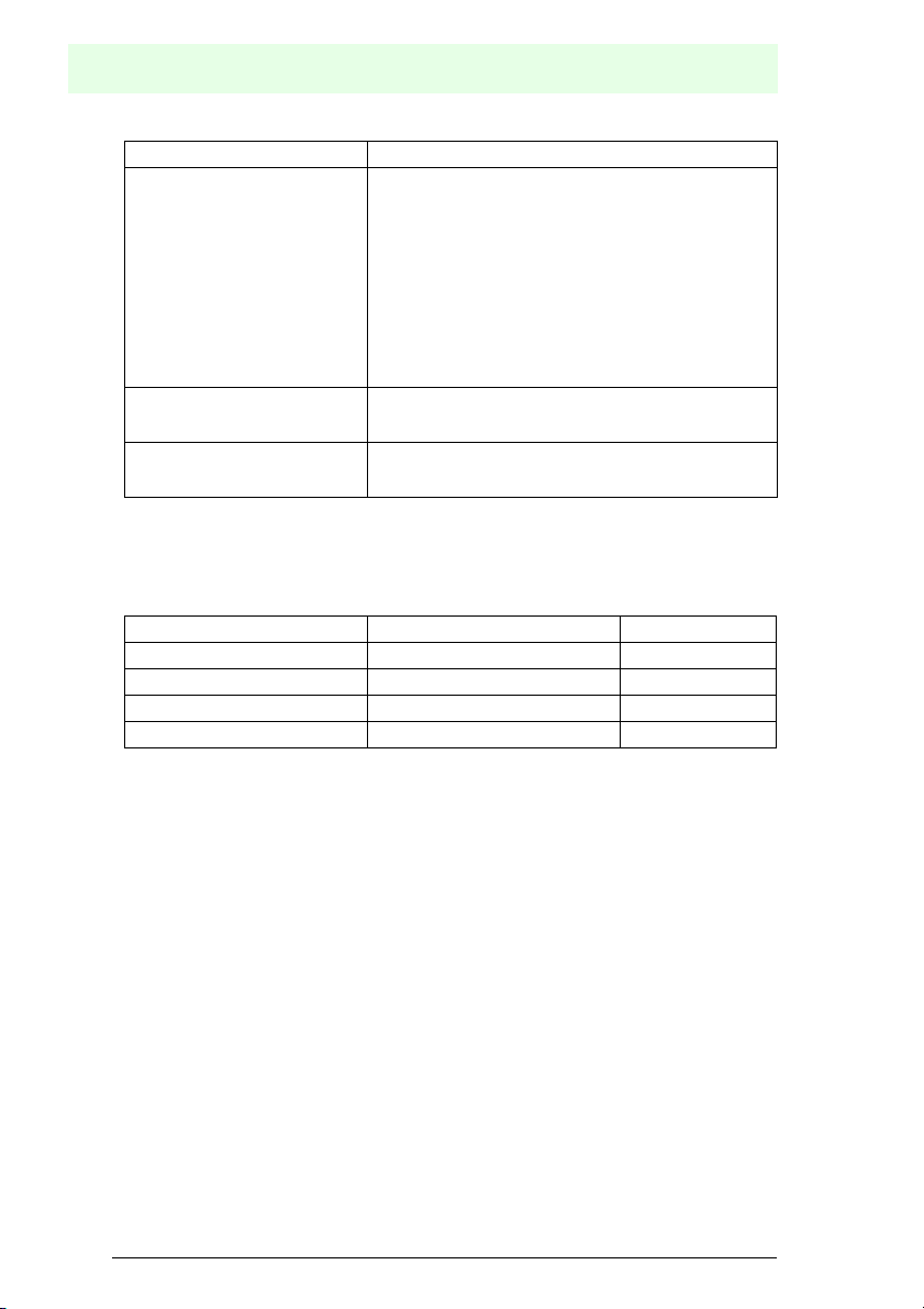
Version Reading Distance
VB14A-600 / VB14A-600-R 190 mm (7.5 in) - 600 mm (23.6 in)
on 0.50 mm (20 mils) codes
VB14A-440 / VB14A-440-R 100 mm (3.9 in) - 440 mm (17.3 in)
on 0.50 mm (20 mils) codes
VB14A-340 / VB14A-340-R 75 mm (3 in) - 340 mm (13.4 in)
on 0.35 mm (14 mils) codes
VB14A-310 / VB14A-310-R 50 mm (1.8 in) - 310 mm (11.8 in)
on 0.50 mm (20 mils) codes
VB14A-100 / VB14A-100-R 45 mm (1.8) - 100 mm (3.9 in)
on 0.20 mm (8 mils) codes
VB14A-300 / VB14A-300-R 40 mm (1.6 in) - 300 mm (11.8 in)
on 0.50mm (20 mils) codes
See reading diagrams see section 7.3 for further details.
5.3 Accessory Installation
The following accessories are available on request for the VB14A:
Name Description Part Number
C-BOX 100 Connection Box 115195
C-BOX 300 Connection Box Profibus 127109
Deflection mirror VB14 Deflection mirror 90° 115196
OM14A Oscillating mirror
Date of issue 12/2005
ubject to reasonable modifications due to technical advances. Copyright Pepperl+Fuchs, Printed in Germany
12
epperl+Fuchs Group • Tel.: Germany (06 21) 7 76-0 • USA (330) 4 25 35 55 • Singapore 7 79 90 91 • Internet http://www.pepperl-fuchs.com
Page 13
Barcode Scanner VB14A
S
P
INSTALLATION
6INSTALLATION
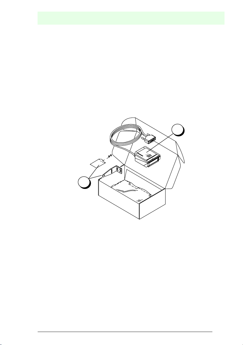
6.1 Package Contents
Verify that the VB14A reader and all the parts supplied with the equipment are present
and intact when opening the packaging; the list of parts includes:
1. VB14 reader with cable
2. Mounting kit: - bracket
- screws
With your order the following items are included:
CD-ROM containing operating manual, configuration tool VisoSetup, and bar code
test chart.
1
2
Figure 6.1 VB14A package contents
Date of issue 12/2005
ubject to reasonable modifications due to technical advances. Copyright Pepperl+Fuchs, Printed in Germany
epperl+Fuchs Group • Tel.: Germany (06 21) 7 76-0 • USA (330) 4 25 35 55 • Singapore 7 79 90 91 • Internet http://www.pepperl-fuchs.com
13
Page 14
Barcode Scanner VB14A
S
P
INSTALLATION
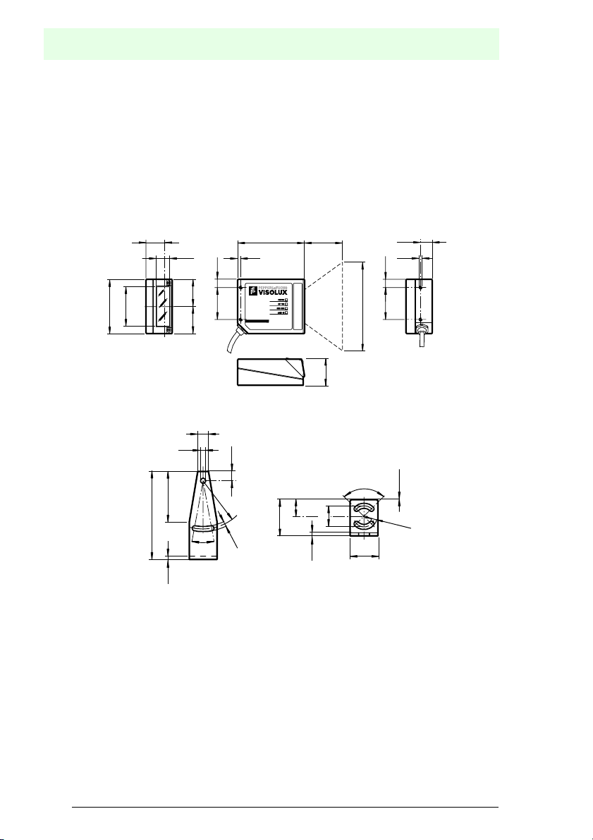
6.1.1 Mechanical Installation
VB14A can be installed to operate in different positions. The four screw holes (M4 x
5) on the body of the reader are for mechanical fixture (figure 3.1 (5)). The diagrams
below give the overall dimensions of the scanner and mounting bracket and may be
used for installation.
see section 6.4 for correct positioning.
VB14A
23.3
14.5
10.3
=
46
68
42
73
2.5
4.2
40.0
=
9
7.8
R 40
4.2
20˚
Figure 6.2 Overall dimensions
A83.6
5
VB14A
34
Mounting bracket
13.8
30
2.5
bottom view
17.5
90˚
14.6
M 4
10.3
B
40.0
1x45˚
4.2
23
Date of issue 12/2005
ubject to reasonable modifications due to technical advances. Copyright Pepperl+Fuchs, Printed in Germany
14
epperl+Fuchs Group • Tel.: Germany (06 21) 7 76-0 • USA (330) 4 25 35 55 • Singapore 7 79 90 91 • Internet http://www.pepperl-fuchs.com
Page 15
Barcode Scanner VB14A
S
P
INSTALLATION
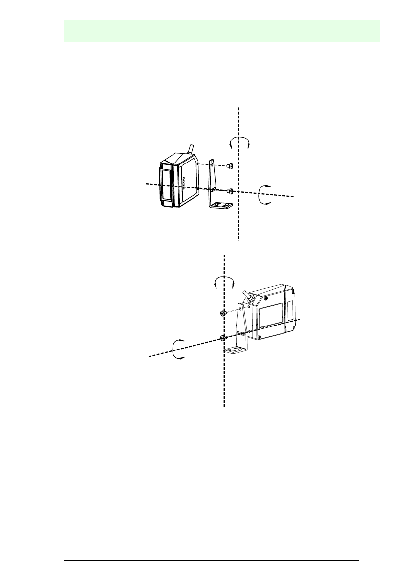
6.1.2 Mounting VB14A
Using the VB14A mounting bracket you can obtain the most suitable position for the
reader as shown in the figure below:
Skew
Pitch
Skew
Tilt
Figure 6.3 Positioning with Mounting Bracket
Date of issue 12/2005
ubject to reasonable modifications due to technical advances. Copyright Pepperl+Fuchs, Printed in Germany
epperl+Fuchs Group • Tel.: Germany (06 21) 7 76-0 • USA (330) 4 25 35 55 • Singapore 7 79 90 91 • Internet http://www.pepperl-fuchs.com
15
Page 16
Barcode Scanner VB14A
S
P
INSTALLATION
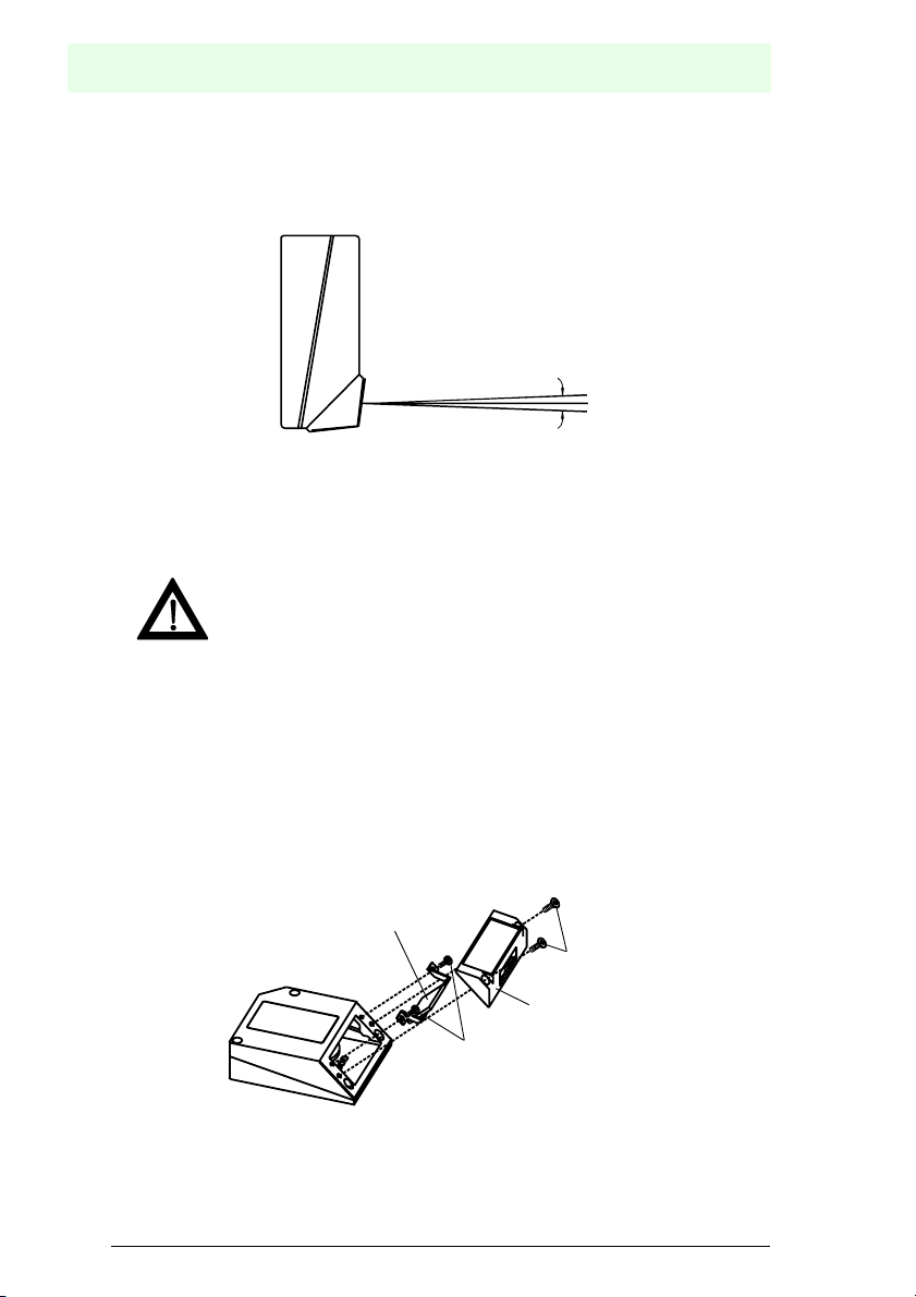
6.1.3 Mounting the Scanner with Deflection Mirror
• "The is a 90° deflection mirror
The reading position with respect to the scanner is shown below for each mirror.
90˚ ± 2˚
Figure 6.4 Laser Beam Output Position
The installation of the deflection mirror is very easy
Avoid any contact with the deflection mirror, mirrored rotor, the lenses
or other optical components, otherwise the performance of the reader
will be reduced.
Warning
1. Turn off the device.
2. Remove the VB14A scanning window unscrewing the two cover screws.
3. Fix the mirror to the device by means of the two fixing screws.
4. Remount the scanning window so that the opening face is now at 90° with
respect to the VB14A body.
Deflection mirror
Cover screws
Scanning window
Fixing screws
Figure 6.5 Installation of the Deflection Mirror
ubject to reasonable modifications due to technical advances. Copyright Pepperl+Fuchs, Printed in Germany
16
epperl+Fuchs Group • Tel.: Germany (06 21) 7 76-0 • USA (330) 4 25 35 55 • Singapore 7 79 90 91 • Internet http://www.pepperl-fuchs.com
Date of issue 12/2005
Page 17
Barcode Scanner VB14A
S
P
INSTALLATION
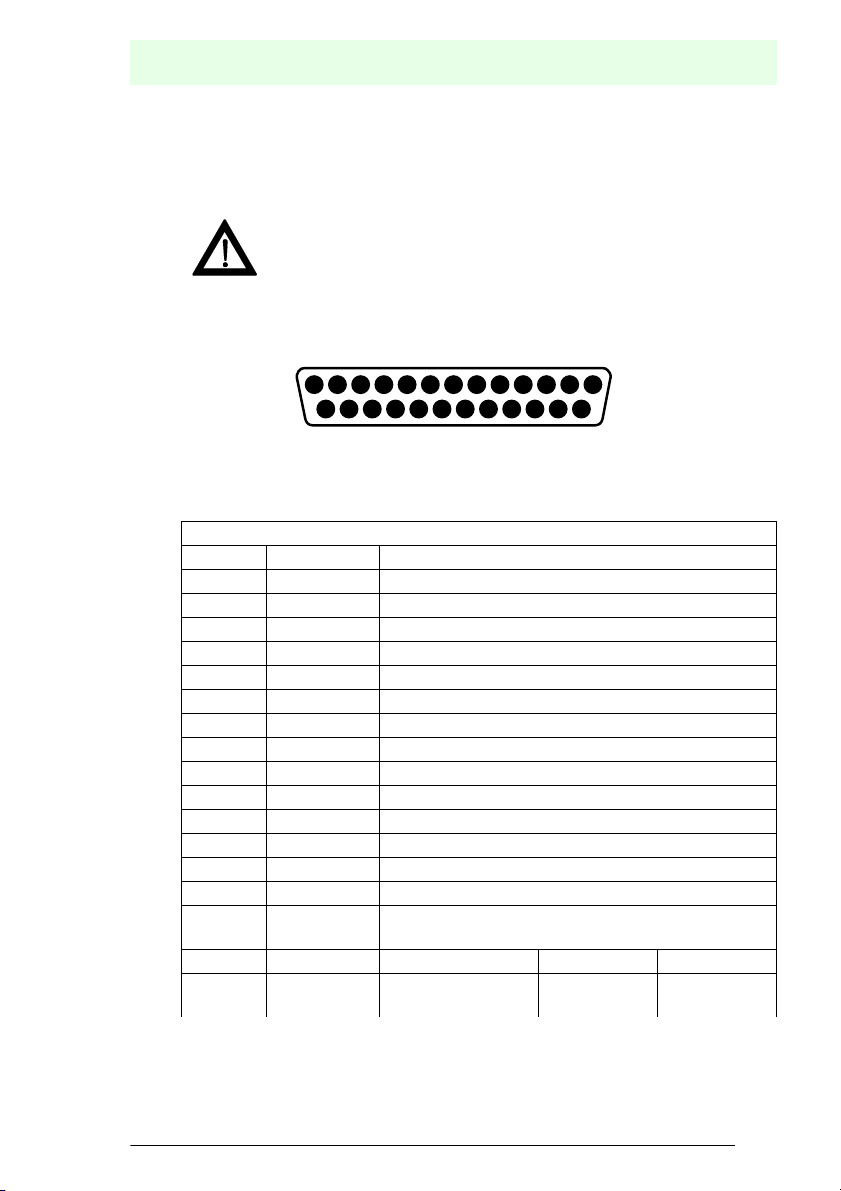
6.2 Electrical Connections
The VB14A models are equipped with a cable terminated by a 25-pin male D-sub
connector for connection to the power supply and input/output signals.
Do not connect GND and SGND to different (external) ground
references. GND and SGND are internally connected through filtering
circuitry which can be permanently damaged if subjected to voltage
Warning
The details of the connector pins are indicated in the following table:
Figure 6.6 25-pin male D-sub connector
6, 10, 14,
15, 16, 17
drops over 0.8 V DC.
113
14 25
25-pin D-sub connector pinout
Pin Name Function
13 10 ... 30 V DC Power supply input voltage +
25 GND Power supply input voltage -
1 CHASSIS Chassis Ground
9 10 … 30V DC External Trigger supply voltage +
18 EXT. TRIG.+ External Trigger +
19 EXT. TRIG.- External Trigger -
8 OUT1 + Output 1 +
11 OUT2 + Output 2 +
12 OUT REF. Output reference
22 OUT REF. Output reference
20 RX232 Auxiliary RX RS232
21 TX232 Auxiliary TX RS232
23 CTS232 Auxiliary hanshake CTS RS232
24 RTS232 Auxiliary handshake RTS RS232
NC Not connected
Pin RS232 RS485
full-duplex
Date of issue 12/2005
ubject to reasonable modifications due to technical advances. Copyright Pepperl+Fuchs, Printed in Germany
epperl+Fuchs Group • Tel.: Germany (06 21) 7 76-0 • USA (330) 4 25 35 55 • Singapore 7 79 90 91 • Internet http://www.pepperl-fuchs.com
RS485
half-duplex
17
Page 18

Barcode Scanner VB14A
S
P
INSTALLATION
2
3 RX232 RX485+
4 RTS232 TX485- RTX4855 CTS232 RX4857 SGND SGND SGND
Main
interface
signals,
see par. 8.
TX232 TX485+ RTX485+
6.2.1 Power supply
Power is supplied to the scanner through the pins provided on the 25- pin connector
used for communication with the host:
USER
VB14A 25-pin
13
25
1
VS
GND
CHASSIS
Earth Ground
INTERFACE
V+ (10- 30 VDC)
VGND
CHASSIS
Figure 6.7 Power supply connections
The power must be between 10 and 30 V DC only.
It is recommended to connect pin 1 (CHASSIS) to a common earth ground.
6.2.2 Main Serial Interface
The signals relative to the following serial interface types are available on the input/
output connector of VB14A.
If the interface type is not compatible with the current communication handshaking,
then the system forces the handshake to none.
The main interface type and relative parameters (baud rate, data bits, etc.) can be set
using the VisoSetup utility program or "Host Mode Programming" procedure through
ESC sequences.
Details regarding the connections and use of the interfaces are given in the next
paragraphs.
RS232 Interface
The serial interface is used in this case for point to point connections; it handles
communication with the host computer and allows both transmission of code data and
the programming of the scanner. This is the default setting.
The following pins are used for RS232 interface connection:
Date of issue 12/2005
ubject to reasonable modifications due to technical advances. Copyright Pepperl+Fuchs, Printed in Germany
18
epperl+Fuchs Group • Tel.: Germany (06 21) 7 76-0 • USA (330) 4 25 35 55 • Singapore 7 79 90 91 • Internet http://www.pepperl-fuchs.com
Page 19

Barcode Scanner VB14A
S
P
INSTALLATION
Connector
Name Function
25-Pin
2 TX232 transmit data
3 RX232 receive data
4 RTS232 request to send
5 CTS232 clear to send
7 GND/SGND signal ground
USER
VB14A 25-pin
2
3
4
5
7
Chassis
1
TX232
RX232
RTS232
CTS232
SGND
INTERFACE
RXD
TXD
DCD
DTR
SGND
Figure 6.8 RS232 main interface connections using hardware handshaking
The RTS232 and CTS232 signals control data transmission and synchronize the
connected devices.
+V
RTS
-V
+V
TX DATA
-V
DATA
TRANSMISSION
TRANSMISSION
C1 C2 C3 C4 C5
TRANSMISSION
DATA
STOPPED
+V
ENABLED ENABLED
RTS
-V
DISABLED
IDLEIDLE
Figure 6.9 RS232 control signals
Date of issue 12/2005
ubject to reasonable modifications due to technical advances. Copyright Pepperl+Fuchs, Printed in Germany
epperl+Fuchs Group • Tel.: Germany (06 21) 7 76-0 • USA (330) 4 25 35 55 • Singapore 7 79 90 91 • Internet http://www.pepperl-fuchs.com
19
Page 20

Barcode Scanner VB14A
S
P
INSTALLATION
If the RTS/CTS handshaking protocol is enabled, the VB14A activates the RTS232
output to indicate a message is to be transmitted. The receiving unit activates the
CTS232 input to enable the transmission.
RS485 full-duplex interface
The RS485 full-duplex interface (5 wires + shield) is used for non-polled
communication protocols in point-to-point connections over longer distances than
those acceptable for RS232 communications or in electrically noisy environments.
The connector pinout follows:
Connector
Name Function
25-pin
2 TX485+ RX485 transmit data +
4 TX485- RX485 transmit data 3 RX485+ RX485 receive data +
5 RX485- RX485 receive data 7 SGND Signal ground
USER
VB14A 25-pin
2
4
3
5
7
Chassis
1
TX485+
TX485-
RX485+
RX485-
SGND
INTERFACE
+
RX485
-
+
TX485
-
+
SGND
Figure 6.10 RS485 full-duplex connections
RS485 Half-Duplex Interface
The RS485 half-duplex (3 wires + shield) interface is used for polled communication
protocols.
It can be used in a master/slave layout, (see Section 6.24) exploiting a proprietary
protocol based on polled mode called MUX32 protocol, where a master device polls
slave devices to collect data.
The connector pinout follows:
Date of issue 12/2005
ubject to reasonable modifications due to technical advances. Copyright Pepperl+Fuchs, Printed in Germany
20
epperl+Fuchs Group • Tel.: Germany (06 21) 7 76-0 • USA (330) 4 25 35 55 • Singapore 7 79 90 91 • Internet http://www.pepperl-fuchs.com
Page 21

Barcode Scanner VB14A
S
P
INSTALLATION
Connector
Name Function
25-pin
2 RTX485+ RX485 transmit/receive data +
4 RTX485- RX485 transmit/receive data 7 SGND signal ground
6.2.3 Auxiliary RS232 Interface
The auxiliary serial interface is used exclusively for RS232 point to point connections.
The parameters relative to the aux interface (baud rate, data bits, etc.) as well as
particular communication modes such as LOCAL ECHO can be defined using the
VisoSetup utility program or "Host Mode Programming", installed from the CD-Rom.
The following pins of the 25-pin connector are used to connect the RS232 auxiliary
interface:
Connector
Name Function
25-pin
20 RXAUX receive data
21 TXAUX transmit data
23 CTSAUX clear to send
24 RTSAUX request to send
7 SGND signal ground
USER
VB14A 25-pin
20
21
23
24
7
Chassis
1
RXAUX
TXAUX
CTSAUX
RTSAUX
SGND
INTERFACE
TXD
RXD
DTR
DCD
SGND
Figure 6.11 RS232 auxiliary interface connections using hardware handshaking
The RTSAUX and CTSAUX signals control data transmission and synchronize the
connected devices. If the RTS/CTS handshaking protocol is enabled, the VB14A
activates the RTSAUX output to indicate a message is to be transmitted. The
receiving unit activates the CTSAUX input to enable the transmission.
Date of issue 12/2005
ubject to reasonable modifications due to technical advances. Copyright Pepperl+Fuchs, Printed in Germany
epperl+Fuchs Group • Tel.: Germany (06 21) 7 76-0 • USA (330) 4 25 35 55 • Singapore 7 79 90 91 • Internet http://www.pepperl-fuchs.com
21
Page 22

Barcode Scanner VB14A
S
P
INSTALLATION
Code Verifier
If the VB14A is used as a Code Verifier, it is possible to indicate to the scanner what
code to store as the verifier code by means of an external hardware input.
The Code Verifier parameter must be enabled and the configuration parameters to
allow correct Code Type reading must be saved to the scanner in order to read the
verifier code.
To activate the input, connect together pins 23 and 24 (CTSAUX and RTSAUX) of the
25-pin connector (for example with a push-button), before the active edge of the
External Trigger input (or before the code passes under the laser beam for the
Automatic operating mode.
The next read code will be stored as the verifier code in the scanner's RAM and NONVOLATILE (EEPROM) memory by default.
Then the two pins must be disconnected.
Since it uses part of the RS232 auxiliary serial interface, this interface is limited when
using this option and the Handshake selection must not be set to RTS/CTS.
6.2.4 Inputs
The inputs available on the connector supplied with the scanner are the pins relative
to the External Trigger, as indicated below:
Connector Name Function
25-Pin
18 EXT TRIG+ external trigger +
19 EXT TRIG- external trigger -
The External Trigger input is used in the On-Line operating Mode and tells the
scanner to scan for a code. The active state of this input is selected in software. Refer
to the VisoSetup Help On Line.
The yellow LED (figure 3.1 (2)) is on when the External Trigger forces a current flow
through the EXT TRIG+ and EXT TRIG- pins.
This input is optocoupled and can be driven by both an NPN or PNP type command.
The connections are indicated in the following diagrams:
VB14A 25-pin
+5 V
V
18
19
30 V DC max.
ext
EXT TRIG+
EXT TRIG-
EXTERNAL
TRIGGER
V
Signal
Figure 6.12 Input NPN command using external power
Date of issue 12/2005
ubject to reasonable modifications due to technical advances. Copyright Pepperl+Fuchs, Printed in Germany
22
epperl+Fuchs Group • Tel.: Germany (06 21) 7 76-0 • USA (330) 4 25 35 55 • Singapore 7 79 90 91 • Internet http://www.pepperl-fuchs.com
Page 23

Barcode Scanner VB14A
S
P
INSTALLATION
VB14A 25-pin
+5 V
9
18
19
25
VS
EXT TRIG+
EXT TRIG-
GND
TRIGGER
V
Ground
Figure 6.13 Input NPN command using VB14A power
EXTERNAL
VB14A 25-pin
+5 V
18
19
30 V DC max.
V
ext
EXT TRIG+
EXT TRIG-
EXTERNAL
TRIGGER
V
Ground
Figure 6.14 Input PNP command using external power
Signal
Signal
VB14A 25-pin
+5 V
9
18
19
25
VS
EXT TRIG+
EXT TRIG-
GND
TRIGGER
V
Signal
Ground
Figure 6.15 Input PNP command using VB14A power
Electrical features: Maximum voltage:30 V DC
Maximum current:25 mA
Date of issue 12/2005
EXTERNAL
ubject to reasonable modifications due to technical advances. Copyright Pepperl+Fuchs, Printed in Germany
epperl+Fuchs Group • Tel.: Germany (06 21) 7 76-0 • USA (330) 4 25 35 55 • Singapore 7 79 90 91 • Internet http://www.pepperl-fuchs.com
23
Page 24

Barcode Scanner VB14A
S
P
INSTALLATION
An anti-disturbance hardware filter is implemented on the External Trigger input
An additional 15 ms (typical) delay can be implemented through a dedicated software
parameter (refer to VisoSetup Help On Line).
6.2.5 Outputs
Two general purpose outputs are available. These outputs can only be connected as
open collector configurations. The following pins are present on the 25-pin connector
of the scanner:
Connector
25-pin
8 OUT1+ output 1 +
11 OUT2+ output 2 +
12, 22 OUT REF output reference
Name Function
VB14A 25-pin
8/11
12/22
OUT 1+ / OUT 2+
OUT REF
INTERFACE
40 V DC max.
V
ext
Figure 6.16 Output connections
Electrical features: Maximum voltage:40 V DC
Maximum current:40 mA continuous
The meaning of the two outputs OUT1 and OUT2 can be defined by the user. Refer
to the VisoSetup Help On Line.
By default, OUT1 is associated with the No Read event, which activates when the
code signaled by the external trigger is not decoded, and OUT2 is associated with the
Right event, which activates when the code is correctly decoded.
These outputs are both level or pulse configurable.
USER
Date of issue 12/2005
ubject to reasonable modifications due to technical advances. Copyright Pepperl+Fuchs, Printed in Germany
24
epperl+Fuchs Group • Tel.: Germany (06 21) 7 76-0 • USA (330) 4 25 35 55 • Singapore 7 79 90 91 • Internet http://www.pepperl-fuchs.com
Page 25

Barcode Scanner VB14A
S
P
INSTALLATION
6.3 User Interface
The following table contains the pinout for standard RS232 PC Host interface. For
other user interface types please refer to their own manual.
RS232 PC side connections
9 pin male connector 25 pin male connector
PinNamePinName
2RX3RX
3TX2TX
5GND7GND
7RTS4RTS
8CTS5CTS
How To Build A Simple Interface Test Cable:
The following wiring diagram shows a simple test cable including power, external
(push-button) trigger and PC RS232 COM port connections.
25-pin D-sub female 9-pin D-sub female
TXAUX
VB14A
21
20
RXAUX
SGND
7
13
VS
25
9
18
19
GND
VS
EXT TRIG+
EXT TRIG
2
3
5
Power Supply
VS (10 – 30 V DC)
Power GND
RX
TX
GND
PC
Trigger
Figure 6.17 Test Cable for VB14A
Date of issue 12/2005
ubject to reasonable modifications due to technical advances. Copyright Pepperl+Fuchs, Printed in Germany
epperl+Fuchs Group • Tel.: Germany (06 21) 7 76-0 • USA (330) 4 25 35 55 • Singapore 7 79 90 91 • Internet http://www.pepperl-fuchs.com
25
Page 26

Barcode Scanner VB14A
S
P
INSTALLATION
6.4 Positioning
The VB14A scanner is able to decode barcode labels at a variety of angles, however
significant angular distortion may degrade reading performance.
When mounting the VB14A take into consideration these three ideal label position
angles: Pitch 0°, Skew 10° to 30° and Tilt 0°.
Follow the suggestions for the best orientation:
The Pitch angle is represented by the
value P in figure 6.21. Position the
reader in order to minimize the Pitch
angle.
The Skew angle is represented by the
value S in figure 6.22. Position the
reader to assure at least 10° for the
Skew angle. This avoids the direct
reflection of the laser light emitted by
the VB14A.For the raster version, this
angle refers to the most inclined or
external raster line, so that all other
raster lines assure more than 10°
Skew.
VB14A
Figure 6.18 Pitch angle
VB14A
Figure 6.19 Skew angle
P
S
The Tilt angle is represented by the
value T in figure 6.24. Position the
T
reader in order to minimize the Tilt
angle.
By using the ACB (Advanced Code
Builder) software parameter, the tilt
angle is less critical and can be
decoded even if the scan see section
VB14A
Figure 6.20 Tilt Angle
6.18 or the Help On Line for details.
Date of issue 12/2005
ubject to reasonable modifications due to technical advances. Copyright Pepperl+Fuchs, Printed in Germany
26
epperl+Fuchs Group • Tel.: Germany (06 21) 7 76-0 • USA (330) 4 25 35 55 • Singapore 7 79 90 91 • Internet http://www.pepperl-fuchs.com
Page 27

S
P
6.5 Typical Layouts
Barcode Scanner VB14A
INSTALLATION
The following typical layouts refer to system hardware configurations
the figures refer to optional hardware configurations within the particular layout.
These layouts also require the correct setup of the software configuration parameters.
Complete software configuration procedures can be found in the Guide To Rapid
Configuration in the VisoSetup Help On Line.
6.5.1 Point-to-Point
In this layout the data is transmitted to the Host on the main serial interface. Host
Mode programming can be accomplished either through the main interface or the
Auxiliary interface.
In Local Echo communication mode, data is transmitted on the RS232 auxiliary
interface independently from the main interface selection.
When On-Line Operating mode is used, the scanner is activated by an External
Trigger (photoelectric sensor) when the object enters its reading zone.
VB14A
VB14A
Terminal
2
1 Main serial interface
2 Auxiliary serial interface (Local Echo)
3 External Trigger (for On-Line mode)
Host
1
3
. Dotted lines in
Figure 6.21 Point to Point layout
Date of issue 12/2005
ubject to reasonable modifications due to technical advances. Copyright Pepperl+Fuchs, Printed in Germany
epperl+Fuchs Group • Tel.: Germany (06 21) 7 76-0 • USA (330) 4 25 35 55 • Singapore 7 79 90 91 • Internet http://www.pepperl-fuchs.com
27
Page 28

Barcode Scanner VB14A
S
P
INSTALLATION
6.5.2 Pass-Through
Pass-through mode allows two or more devices to be connected to a single external
serial interface.
Each VB14A transmits the messages received by the Auxiliary interface onto the
main interface. All messages will be passed through this chain to the host.
When On-Line Operating mode is used, the scanner is activated by an External
Trigger (photoelectric sensor) when the object enters its reading zone.
The Main and Auxiliary ports are connected as shown in the following figure:
1 Main serial interface
2 Auxiliary serial interface
3 External Trigger (for On-Line mode)
2
1
VB14A
VB14A
Host
VB14A
VB14A
1
3
3
Figure 6.22 Pass-through layout
Date of issue 12/2005
ubject to reasonable modifications due to technical advances. Copyright Pepperl+Fuchs, Printed in Germany
28
epperl+Fuchs Group • Tel.: Germany (06 21) 7 76-0 • USA (330) 4 25 35 55 • Singapore 7 79 90 91 • Internet http://www.pepperl-fuchs.com
Page 29

Barcode Scanner VB14A
S
P
INSTALLATION
6.5.3 RS232 Master/Slave
The RS232 master/slave connection is used to collect data from several scanners to
build either a multi-point or a multi-sided reading system; there can be one master and
up to 9 slaves connected together.
The Slave scanners use RS232 only on the main and auxiliary serial interfaces. Each
slave VB14A transmits the messages received by the auxiliary interface onto the main
interface. All messages will be passed through this chain to the master.
The master scanner is connected to the Host on the main serial interface. The
possible main interface types for the master scanner are RS232 or RS485.
Either On-Line
When On-Line Operating mode is used, the external trigger signal is unique to the
system, however it is not necessary to bring the external trigger signal to the Slave
scanners.
The main and auxiliary ports are connected as shown in the figure below.
or Serial On-Line Operating modes can be used in this layout.
1
2
VB14A
VB14A
MASTER
VB14A
SLAVE
VB14A
VB14A
2
VB14A
SLAVE
1
1
1 Main serial interface
2 Auxiliary serial interface
3
Host
3 External Trigger (for On-Line mode)
Figure 6.23 RS232 Master/slave layout
Date of issue 12/2005
ubject to reasonable modifications due to technical advances. Copyright Pepperl+Fuchs, Printed in Germany
epperl+Fuchs Group • Tel.: Germany (06 21) 7 76-0 • USA (330) 4 25 35 55 • Singapore 7 79 90 91 • Internet http://www.pepperl-fuchs.com
29
Page 30

Barcode Scanner VB14A
S
P
INSTALLATION
6.5.4 RS485 Master/Slave
The RS485 master/slave connection is used to collect data from several scanners to
build a multi-point or a multi-sided reading system; there can be one master and up
to 5 slaves connected together.
The slave scanners are connected together using RS485 half-duplex on the main
serial interface. Every slave scanner must have a multidrop address in the range 0-4.
The master scanner is also connected to the Host on the RS232 auxiliary serial
interface.
The External Trigger signal is unique to the system; there is a single reading phase
and a single message from the master scanner to the Host computer.
It is necessary to bring the External Trigger signal to all the scanners.
The main and auxiliary ports are connected as shown in the figure below.
1 Auxiliary serial interface
2 RS485HD Main serial interface
Host
3 External Trigger
2
VB14A
VB14A
MASTER
VB14A
SLAVE
VB14A
1
1
VB14A
VB14A
SLAVE
3
Figure 6.24 RS485 Master/slave layout
The auxiliary serial interface of the slave scanners can be used in Local
Echo communication mode to control any single scanner (visualize
collected data) or to configure it using the VisoSetup utility or Host
Information
Mode programming procedure.
The termination resistors of the RS485 bus must not be installed.
The termination resistors of the RS485 bus must not be installed.
1
Date of issue 12/2005
ubject to reasonable modifications due to technical advances. Copyright Pepperl+Fuchs, Printed in Germany
30
epperl+Fuchs Group • Tel.: Germany (06 21) 7 76-0 • USA (330) 4 25 35 55 • Singapore 7 79 90 91 • Internet http://www.pepperl-fuchs.com
Page 31

Barcode Scanner VB14A
S
P
READING FEATURES
7 READING FEATURES
7.1 Advanced Code Builder (ACB)
In addition to linear reading, the Advanced Code Builder (ACB) allows code reading
by "stitching" together two partial reads of it. ACB is effective in the case of close-tolinear, small height codes, damaged codes, or poor print quality codes.
ACB is used to read a code label when the scan line does not cross the label along
its entire length (excessive tilt angle).
www.pepperl-fuchs.com
Linear Reading
www.pepperl-fuchs.com
ACB Reading
www.pepperl-fuchs.com
Linear Reading
www.pepperl-fuchs.com
ACB Reading
ACB reads two fragments of a label containing a start or a stop character and a
number of digits, and puts them together to build the complete label.
ACB also has an intrinsic ability to increase the reading percentage of damaged
codes as in the examples below:
www.pepperl-fuchs.com
ACB Readable
www.pepperl-fuchs.com
Not ACB Readable
Date of issue 12/2005
ubject to reasonable modifications due to technical advances. Copyright Pepperl+Fuchs, Printed in Germany
epperl+Fuchs Group • Tel.: Germany (06 21) 7 76-0 • USA (330) 4 25 35 55 • Singapore 7 79 90 91 • Internet http://www.pepperl-fuchs.com
31
Page 32

Barcode Scanner VB14A
S
P
READING FEATURES
www.pepperl-fuchs.com
ACB Readable
ACB is disabled by default but can be enabled for the following code types:
• "Code 25 Interleaved • "Code 128/EAN128
• "Code 39 Family • "EAN/UPC (without ADD-Ons)
• "Codebar • "Code 93
7.1.1 Important ACB Reading Conditions
• "Do not use ACB for omni-directional reading stations.
• "ACB can be activated for each symbologies independently from the others.
• "ACB requires that the code be in movement with respect to the scanner.
• "ACB requires fixed length barcode reading.
• "The codes read with ACB enabled must pass in front of the scanner one at a time.
www.pepperl-fuchs.com
Not valid for ACB
www.pepperl-fuchs.com
www.pepperl-fuchs.com
Valid for ACB
• "Code concatenation and ACB are not compatible and therefore cannot be enabled
simultaneously on the same code.
• "For correct operation, ACB requires at least 5 scans for each of the two fragments.
Date of issue 12/2005
ubject to reasonable modifications due to technical advances. Copyright Pepperl+Fuchs, Printed in Germany
32
epperl+Fuchs Group • Tel.: Germany (06 21) 7 76-0 • USA (330) 4 25 35 55 • Singapore 7 79 90 91 • Internet http://www.pepperl-fuchs.com
Page 33

Barcode Scanner VB14A
S
P
L
H
READING FEATURES
7.1.2 Tilt Angle Improvement with ACB
ACB allows barcode reading with an increased tilt angle. The tilt angle depends upon
the code aspect ratio defined as H/L according to the table below:
L
H
www.pepperl-fuchs.com
Aspect Ratio
H/L
Max theoretical lin-
ear tilt angle
Max practical
ACB angle
0.33 18° 30°
0.25 14° 23°
0.125 7° 11°
7.2 Linear Code Reading
For linear code reading, the number of scans performed on the code by the VB14A
and therefore the decoding capability is influenced by the following parameters:
• "number of scans per second
• "code motion speed
• "label dimensions
• "scan direction with respect to code motion
About 5 scans during the code passage should be allowed to ensure a successful
read.
7.2.1 Step-Ladder mode
If scanning is perpendicular to the code motion direction (figure 7.1 - "step-ladder"
mode), the number of effective scans performed by the reader is given by the
following formula:
SN = [(LH/LS) ∗ SS] - 2 Where: SN = number of effective scans
LH = label height (in mm)
LS = Label movement speed in (mm/s)
SS = number of scans per second
Date of issue 12/2005
ubject to reasonable modifications due to technical advances. Copyright Pepperl+Fuchs, Printed in Germany
epperl+Fuchs Group • Tel.: Germany (06 21) 7 76-0 • USA (330) 4 25 35 55 • Singapore 7 79 90 91 • Internet http://www.pepperl-fuchs.com
33
Page 34

Barcode Scanner VB14A
S
P
READING FEATURES
Direction of code
movement at LS speed
LH
VB14A
Laser
beam
Figure 7.1 "Step-Ladder" scanning mode
For example, the VB14-440 (800 scans/sec.) for a 25 mm high code moving at 1250
mm/s performs:
[(25/1250) ∗ 800] - 2 = 14 effective scans
7.2.2 Picket-Fence mode
If scanning is parallel to the code motion, (figure 7.2 - "picket-fence" mode), the
number of effective scans is given by the following formula:
SN = [((FW-LW)/LS) ∗ SS] - 2 Where: SN = number of effective scans
FW = reading field width (in mm)
LW = label width (in mm)
LS = label movement speed (in mm/s)
SS = scans per second
Code motion
direction
at LS speed
Laser
VB14A
LW
FW
beam
Figure 7.2 "Picket-Fence" scanning mode
Date of issue 12/2005
ubject to reasonable modifications due to technical advances. Copyright Pepperl+Fuchs, Printed in Germany
34
epperl+Fuchs Group • Tel.: Germany (06 21) 7 76-0 • USA (330) 4 25 35 55 • Singapore 7 79 90 91 • Internet http://www.pepperl-fuchs.com
Page 35

Barcode Scanner VB14A
S
P
READING FEATURES
For example, for a 100 mm wide code moving in a point where the reading field is 200
mm wide at a 2000 mm/s speed, the VB14-440 (800 scans per sec.), performs:
[((200-100)/2000 ∗ 800] - 2 = 38 scans
7.3 Performance
The VB14A scanner is available in different versions according to the reading
performance.
Version Max Code Resolution
mm (mils)
VB14A-600 / VB14A-600-R 0.35 (14) 600 to 1000
VB14A-440 / VB14A-440-R 0.25 (10) 600 to 1000
VB14A-340 / VB14A-340-R 0.20 (8) 600 to 1000
VB14A-310 / VB14A-310-R 0.20 (8) 800 to 1000
VB14A-100 / VB14A-100-R 0.12 (5) 800 to 1000
VB14A-300 / VB14A-300-R 0.20 (8) 500 to 800
Version Reading Distance
VB14A-600 / VB14A-600-R 190 mm (7.5 in) - 600 mm (23.6 in)
on 0.50 mm (20 mils) codes
VB14A-440 / VB14A-440-R 100 mm (3.9 in) - 440 mm (17.3 in)
on 0.50 mm (20 mils) codes
VB14A-340 / VB14A-340-R 75 mm (3 in) - 340 mm (13.4 in)
on 0.35 mm (14 mils) codes
VB14A-310 / VB14A-310-R 50 mm (1.8 in) - 310 mm (11.8 in)
on 0.50 mm (20 mils) codes
VB14A-100 / VB14A-100-R 45 mm (1.8) - 100 mm (3.9 in)
on 0.20 mm (8 mils) codes
VB14A-300 / VB14A-300-R 40 mm (1.6 in) - 300 mm (11.8 in)
on 0.50mm (20 mils) codes
Refer to the diagrams given in see section 7.3.1 for further details on the reading
features. They are taken on various resolution sample codes at a 25 *C ambient
temperature, depending on the conditions in the notes under the diagrams.
Speed
scans/s
Date of issue 12/2005
ubject to reasonable modifications due to technical advances. Copyright Pepperl+Fuchs, Printed in Germany
epperl+Fuchs Group • Tel.: Germany (06 21) 7 76-0 • USA (330) 4 25 35 55 • Singapore 7 79 90 91 • Internet http://www.pepperl-fuchs.com
35
Page 36

Barcode Scanner VB14A
S
P
READING FEATURES
7.3.1 Raster
Raster versions are available. If standard devices do not satisfy specific
requirements, contact your nearest P+F distributor, supplying code samples, to obtain
complete information on the reading possibilities.
The reading characteristics for the raster version is given in the table below. The
distance between the top and bottom scan lines is given at different reading distances
measured from the laser beam output window.
Reading Distance
300 mm
(11.8 in)
Raster Capture 18 mm
(0.7 in)
The max. capture of the Raster version is 18 mm (0.7 in) at 300 mm (11.8 in).
600 mm
(23.6 in)
35 mm
(1.4 in)
Date of issue 12/2005
ubject to reasonable modifications due to technical advances. Copyright Pepperl+Fuchs, Printed in Germany
36
epperl+Fuchs Group • Tel.: Germany (06 21) 7 76-0 • USA (330) 4 25 35 55 • Singapore 7 79 90 91 • Internet http://www.pepperl-fuchs.com
Page 37

S
P
7.4 Reading Diagrams
VB14A-600 and VB14A-600-R
Barcode Scanner VB14A
READING FEATURES
4
10 20 30 40 50 60 70 cm
8
20
6
15
4
10
2
5
0
0
5
2
10
4
15
6
20
8
cm
in
8
12
16 20
0.35 mm
(14 mils)
≥0.50 mm
(20 mils)
Figure 7.3 Raster VB14A-600 and VB14A-600-R
CONDITIONS
=
Optic Version
Linear
Code = Interleaved 2/5 or Code 39
PCS = 0.90
"Pitch" angle = 0°
"Skew" angle = 10°
"Tilt" angle = 0°
*Code Resolution = High for 0.35 mm (14 mils) codes
Standard for 0.50 mm (20 mils) codes and greater
*Code Reading Condition = Standard
*Scanning Speed = Speed_3 (800 scans/sec)
* Parameters selectable in VisoSetup.
24
28 in
Date of issue 12/2005
ubject to reasonable modifications due to technical advances. Copyright Pepperl+Fuchs, Printed in Germany
epperl+Fuchs Group • Tel.: Germany (06 21) 7 76-0 • USA (330) 4 25 35 55 • Singapore 7 79 90 91 • Internet http://www.pepperl-fuchs.com
37
Page 38

Barcode Scanner VB14A
S
P
READING FEATURES
VB14A-440 and VB14A-440-R
412
10 20 30 40 50 cm
8
20
6
15
4
10
2
5
0
0
5
2
10
4
15
6
20
8
cm
in
Note: (0,0) is the center of the laser beam output window.
8
0.35 mm
(14 mils)
0.25 mm
(10 mils)
16
≥
0.50 mm
(20 mils)
Figure 7.4 Raster VB14A-440 and VB14A-440-R
CONDITIONS
Optic Version = Linear
Code = Interleaved 2/5 or Code 39
PCS = 0.90
"Pitch" angle = 0°
"Skew" angle = 10°
"Tilt" angle = 0°
*Code Resolution = High for 0.25 mm (10 mils) codes
Standard for 0.35 mm, (14 mils) codes and greater
*Code Reading Condition = Standard
*Scanning Speed = Speed_3 (800 scans/sec)
* Parameters selectable in VisoSetup.
20
Date of issue 12/2005
ubject to reasonable modifications due to technical advances. Copyright Pepperl+Fuchs, Printed in Germany
38
epperl+Fuchs Group • Tel.: Germany (06 21) 7 76-0 • USA (330) 4 25 35 55 • Singapore 7 79 90 91 • Internet http://www.pepperl-fuchs.com
Page 39

S
P
VB14A-340 and VB14A-340-R
Barcode Scanner VB14A
READING FEATURES
2
51015
4
10
7,5
3
5
2
2,5
1
0
0
2,5
1
5
2
7,5
3
10
4
in
cm
4
6
20 25 30 35 cm
0.20 mm
(8 mils)
10
8
Note: (0,0) is the center of the laser beam output window.
Figure 7.5 Raster VB14A-340 and VB14A-340-R
CONDITIONS
Optic Version = Linear
Code = Interleaved 2/5 or Code 39
PCS = 0.90
"Pitch" angle = 0°
"Skew" angle = 10°
"Tilt" angle = 0°
*Code Resolution* = High
*Code Reading Condition Standard
*Scanning Speed Speed_3 (800 scans/sec)
* Parameters selectable in VisoSetup.
12
0.25 mm
(10 mils)
≥0.35 mm
(14 mils)
14 in
Date of issue 12/2005
ubject to reasonable modifications due to technical advances. Copyright Pepperl+Fuchs, Printed in Germany
epperl+Fuchs Group • Tel.: Germany (06 21) 7 76-0 • USA (330) 4 25 35 55 • Singapore 7 79 90 91 • Internet http://www.pepperl-fuchs.com
39
Page 40

Barcode Scanner VB14A
S
P
0
)
0 40
0
0
0
0
0
0
0
0
0
0
0
0
2
READING FEATURES
VB14A-310 and VB14A-310-R
0 1 3 2 1
5
12
10
4
8
3
6
2
4
1
2
0
0
2
1
4
2
6
3
8
10
4
12
5
(mm)
(in)
60 80 100 120 140 160 180 200 220 240 260
0 2
NOTE: (0,0) is the center of the laser beam output window.
Figure 7.6 Raster VB14A-310 and VB14A-310-R
4 5 7 8 9
0.15 mm
(6 mils)
0.20 mm
(8 mils)
(in
1
300
(mm)
6
11
280
≥
0.30 mm
(12 mils)
0.50 mm
(20 mils)
CONDITIONS
Optic Version = Linear
Code = Interleaved 2/5 or Code 39
PCS = 0.90
"Pitch" angle = 0°
"Skew" angle = 15°
"Tilt" angle = 0°
*Code Resolution* = High for 0.30 mm, (12 mils) codes and smaller
Standard for 0.50 mm (20 mils) codes and greater
*Code Reading Condition Standard
*Scanning Speed 1000 scans/s
* Parameters selectable in VisoSetup
Date of issue 12/2005
ubject to reasonable modifications due to technical advances. Copyright Pepperl+Fuchs, Printed in Germany
40
epperl+Fuchs Group • Tel.: Germany (06 21) 7 76-0 • USA (330) 4 25 35 55 • Singapore 7 79 90 91 • Internet http://www.pepperl-fuchs.com
Page 41

Barcode Scanner VB14A
S
P
)
0
0
0
0
0
0
0
0
0
)
VB14A-100 and VB14A-100-R
0 1 5 3
0
10
2
60
2
50
40
30
1
2
1
0
0
1
2
1
30
40
50
2
60
(mm
(in)
NOTE:(0,0) is the center of the laser beam output window.
Figure 7.7 Raster VB14A-100 and VB14A-100-R
2 4
50 60
0.12 mm
(5 mils)
70 80
40
30
10
90
READING FEATURES
(in
(mm)
12
13
≥
0.20 mm
(8 mils)
0.15 mm
(6 mils)
11
CONDITIONS
Optic Version = Linear
Code = Interleaved 2/5 or Code 39
PCS = 0.90
"Pitch" angle = 0°
"Skew" angle = 15°
"Tilt" angle = 0°
*Code Resolution* = High for 0.15 mm (6 mils) codes and small
Standard for 0.20 mm (8 mils) codes
*Code Reading Condition Standard
*Scanning Speed 1000 scans/s
* Parameters selectable in VisoSetup
Date of issue 12/2005
ubject to reasonable modifications due to technical advances. Copyright Pepperl+Fuchs, Printed in Germany
epperl+Fuchs Group • Tel.: Germany (06 21) 7 76-0 • USA (330) 4 25 35 55 • Singapore 7 79 90 91 • Internet http://www.pepperl-fuchs.com
41
Page 42

Barcode Scanner VB14A
S
P
0
0
0
0
)
)
0 40
)
0
2
READING FEATURES
VB14A-300 and VB14A-300-R
0 1 3 2 10 6
5
120
100
4
80
3
60
2
4
1
20
0
20
1
40
2
6
3
8
100
4
120
5
(mm
(in)
CONDITIONS
0 2
60 80 100 120 140 160 180 200 220 240 260
NOTE: (0,0) is the center of the laser beam output window.
4 5 7 8 9
0.35 mm
0.20 mm
(8 mils)
0.30 mm
(12 mils)
(14 mils)
≥
0.50 mm
(20 mils)
(in
11
28
1
(mm
300
Optic Version = Linear
Code = Interleaved 2/5 or Code 39
PCS = 0.90
"Pitch" angle = 0°
"Skew" angle = 15°
"Tilt" angle = 0°
*Code Reading Condition Standard
*Scanning Speed 500 scans/s
* Parameters selectable in VisoSetup
Date of issue 12/2005
ubject to reasonable modifications due to technical advances. Copyright Pepperl+Fuchs, Printed in Germany
42
epperl+Fuchs Group • Tel.: Germany (06 21) 7 76-0 • USA (330) 4 25 35 55 • Singapore 7 79 90 91 • Internet http://www.pepperl-fuchs.com
Page 43

S
P
VB14A-300-R
)
0 40
)
0
2
0.50 mm
0.35 mm
0.30 mm
Distance
0 1 3 2 10 6
0 2
4 5 7 8 9
60 80 100 120 140 160 180 200 220 240 260
Barcode Scanner VB14A
READING FEATURES
(in
11
1
(mm
300
28
0.20 mm
Code
Resolution
Figure 7.8 Reading Distance vs Scanning Speed
500 scans/s
800 scans/s
Date of issue 12/2005
ubject to reasonable modifications due to technical advances. Copyright Pepperl+Fuchs, Printed in Germany
epperl+Fuchs Group • Tel.: Germany (06 21) 7 76-0 • USA (330) 4 25 35 55 • Singapore 7 79 90 91 • Internet http://www.pepperl-fuchs.com
43
Page 44

Barcode Scanner VB14A
S
P
MAINTENANCE
8 MAINTENANCE
8.1 Cleaning
Clean the laser beam output window periodically for continued correct operation of
the reader.
Dust, dirt, etc. on the window may alter the reading performance.
Repeat the operation frequently in particularly dirty environments.
Use soft material and alcohol to clean the window and avoid any abrasive
substances.
Clean the window of the VB14A when the scanner is turned off or, at
least, when the laser beam is deactivated.
Warning
Date of issue 12/2005
ubject to reasonable modifications due to technical advances. Copyright Pepperl+Fuchs, Printed in Germany
44
epperl+Fuchs Group • Tel.: Germany (06 21) 7 76-0 • USA (330) 4 25 35 55 • Singapore 7 79 90 91 • Internet http://www.pepperl-fuchs.com
Page 45

Barcode Scanner VB14A
S
P
TROUBLESHOOTING
9 TROUBLESHOOTING
9.1 General Guidelines
• "When wiring the device, pay careful attention to the pin number of the signals and
whether you are referring to the scanner connector or to the C-BOX 100 spring
clamp connectors.
• "If you need information about a certain reader parameter you can refer to the VisoSetup? program help files. Either connect the device and select the parameter
you're interested in by pressing the F1 key, or select Help/Contents/VB14A Configuration from the command menu.
• "If you're unable to fix the problem and you're going to contact your local Pepperl+Fuchs distributor, we suggest providing (if possible) the Device Configuration
files (*.cfg). Connect through VisoSetup? and click the Save icon from the edit configuration window. Also note the exact Model, Serial Number and Order Number of
the device.
Figure 9.1 Safe Icon Software
Date of issue 12/2005
ubject to reasonable modifications due to technical advances. Copyright Pepperl+Fuchs, Printed in Germany
epperl+Fuchs Group • Tel.: Germany (06 21) 7 76-0 • USA (330) 4 25 35 55 • Singapore 7 79 90 91 • Internet http://www.pepperl-fuchs.com
45
Page 46

Barcode Scanner VB14A
S
P
TROUBLESHOOTING
TROUBLESHOOTING GUIDE
Problem Suggestions
Power On:
the "Power On"/
"Ready" LED is
not lit
On line Mode:
EXT TRIGGER
LED is correctly
lit but nothing
happens (no
reading results)
Serial On line
Mode:
the reader is not
triggered (no
reading results)
On line Mode
and Serial On
Line:
Reader doesn't
respond correctly to the
expected external signals end
• "Is power connected?
• "If using a power adapter, is it connected to a wall outlet?
• "If using rail power, does rail have power?
• "If using C-Box 100, does it have power (check switch
and LED)?
• "Measure voltage either at pin 13 and pin 25 (for 25-pin
connector) or at spring clamp 1 and 2 (for C-BOX 100).
• "Is the software configuration consistent with the application condition (operating mode etc.)?
• In the VisoSetup program select the OPERATING
MODE tab and check for related parameters
• "In the VisoSetup program select the OPERATING
MODE tab and check if serial on line is enabled as operating mode
• "Are the Start - Stop characters correctly assigned?
• "Is the serial trigger source correctly connected and configured?
• "In the VisoSetup program select the OPERATING
MODE tab and check the TIMEOUT parameterization
Date of issue 12/2005
ubject to reasonable modifications due to technical advances. Copyright Pepperl+Fuchs, Printed in Germany
46
epperl+Fuchs Group • Tel.: Germany (06 21) 7 76-0 • USA (330) 4 25 35 55 • Singapore 7 79 90 91 • Internet http://www.pepperl-fuchs.com
Page 47

Barcode Scanner VB14A
S
P
TROUBLESHOOTING
Reading:
Not possible to
read the target
barcode (always
returns No
Read)
Communication:
Device is not
transmitting
anything to the
host
Communication:
Data transferred to the
host are incorrect, corrupted
or incomplete
Communication:
Always returns
the Reader Failure Character
(<BEL>char as
default)
How do I
obtain my
units' serial
numbers?
• "Check synchronization of reading pulse with object to
read
• "Is the scan line correctly positioned?
• "Place barcode in the center of scan line and run TEST
MODE (selectable by VisoSetup as an Operating Mode).
• If you still have trouble, check the following:
• "Is the reading distance within that allowed (see reading
diagrams)?
• "Is the Tilt angle too large?
• "Is the Skew angle less than 10° (direct reflection)?
• "Choose the CODE tab and enable different code types
(except Pharmacode). LENGTH = Variable
• "Is the Bar Code quality sufficient?
• "If you had no success, try to perform the test using the
BARCODE TEST CHART included with the product.
• "Is the serial cable connected?
• "Is the correct wiring respected?
• "Are serial host settings equivalent to the serial device
setting?
• "If using C-BOX 100, be sure the RS485 termination
switch is positioned to OFF.
• "In the VisoSetup program select the DATA FORMAT
tab and check for values of HEADER, TERMINATOR,
SEPARATOR, FILL CHARACTERS
• "Also check the CODE FIELD LENGTH value
• "Are the COM port parameters correctly assigned?
• "Contact your local Pepperl+Fuchs distributor , because
either a Motor or Laser failure has occurred.
• "Note the exact model and Serial Number of the device
• "The device's serial number is printed on a label that is
affixed to the body of the reader.
• "Serial numbers consist of 9 characters: one letter, 2
numbers, and another letter followed by 5 numbers.
Date of issue 12/2005
ubject to reasonable modifications due to technical advances. Copyright Pepperl+Fuchs, Printed in Germany
epperl+Fuchs Group • Tel.: Germany (06 21) 7 76-0 • USA (330) 4 25 35 55 • Singapore 7 79 90 91 • Internet http://www.pepperl-fuchs.com
47
Page 48

Barcode Scanner VB14A
S
P
TECHNICAL FEATURES
10 TECHNICAL FEATURES
VB14A
-600
-600R
ELECTRICAL FEATURES
INPUT POWER
10 to 30 V DC
Supply voltage
Power consumption
max.
5 W 4 W 3 W
SERIAL INTERFACE (depends on model)
Main RS232; RS485 Full-duplex/Half-duplex
Auxiliary RS232
Baud Rates 150 to 115200
INPUTS
(optocoupled NPN or PNP)
External Trigger
Voltage max. 30 V DC
INPUT current max. 25 mA
OUTPUTS
(optocoupled)
OUT1, OUT2
max. 40 V DC
V
CE
Collector current max. 40 mA continuous; 130 mA pulsed
saturation 0 V at 10 mA max.
V
CE
Power dissipation max. 90 mW at 40 °C (Ambient temp.)
OPTICAL FEATURES
Light source Semiconductor laser diode
Wave lenght (note 1) 630 to 680 nm
Ambient light immunity Complete immunity
Safety class Class 2 - IEC 825-1; Class II - CDRH
READING FEATURES (Note 2)
Scan rate (Note 3) 600 to 1000 scans/sec. 800 to 1000
Aperture angle 50° 60°
Maximum Reading Dis-
tance mm (inch)
Maximum resolution mm
(mils)
600
(23.6)
0.35
(14)
USER INTERFACE
LED indicators laser ON, good read, external trigger, data tx/power ON
-440
-440R
440
(17.3)
0.25
(10)
-340
-340R
340
(13.4)
0.20
(8)
-310
-310R
scans/sec.
310
(12.2)
0.20
(8)
-100
-100R
100
(3.9)
0.12
(5)
-300
-300R
500 to
800
scans/
sec.
300
(11.8)
0.20
(8)
Date of issue 12/2005
ubject to reasonable modifications due to technical advances. Copyright Pepperl+Fuchs, Printed in Germany
48
epperl+Fuchs Group • Tel.: Germany (06 21) 7 76-0 • USA (330) 4 25 35 55 • Singapore 7 79 90 91 • Internet http://www.pepperl-fuchs.com
Page 49

Barcode Scanner VB14A
S
P
TECHNICAL FEATURES
VB14A
-600
-600R
SOFTWARE FEATURES
Readable Code
Symbologies
• EAN/UPC
• EAN/UPC (with Add-on 2 and Add-on 5)
• 2/5 Interleaved
• Code 39 (Standard and Full ASCII)
• Codabar
• Code 93
• Code 128
• EAN 128
• ISBT 128
• Pharmacode
* = ACB Readable. Other symbologies available on
request
Code Selection up to six different codes during
one reading phase
Decoding Safety can enable multiple good reads
Headers and Terminators
of same code
up to four headers and four terminators
Operating Modes On-Line, Automatic, Serial-On-Line, Test
Configuration Modes • through menus using VisoSetup utility
• receiving commands from one of the serial ports
Special Functions ACB (Advanced Code Builder) Motor Off
Parameter Storage Non-volatile internal EEPROM
ENVIRONMENTAL FEATURES
Operating temperature
(Note 4)
0 to 40 °C (32 to 104 °F)
Storage temperature -20 to 70 °C (-4 to 158 °F)
Humidity max. 90% non condensing
Vibration resistance IEC 68-2-6 test FC 1.5 mm;
10 to 55 Hz; 2 hours on each axis
Shock resistance IEC 68-2-27 test EA 30G;
11 ms; 3 shocks on each axis
Protection class IP65
PHYSICAL FEATURES
Mechanical demensions 68 x 84 x 34 mm
Weight 330g. (11.64 oz.) 300 g. (10.6 oz.)
Note 1: The features given are typical at a 25 *C ambient t emperature (if not otherwise indicated).
Note 2: Further details given in par. 3.3.
Note 3: software programmable
Date of issue 12/2005
Note 4: If the reader is used in high temperature environmen ts (over 35 *C), use of the Beam-shutter is advised
(see the VisoSetup configuration program).
ubject to reasonable modifications due to technical advances. Copyright Pepperl+Fuchs, Printed in Germany
epperl+Fuchs Group • Tel.: Germany (06 21) 7 76-0 • USA (330) 4 25 35 55 • Singapore 7 79 90 91 • Internet http://www.pepperl-fuchs.com
-440
-440R
(HOST MODE)
-340
-340R
-310
-310R
-100
-100R
-300
-300R
49
Page 50

Barcode Scanner VB14A
S
P
Glossary
11 Glossary
ACB (Advanced Code Builder)
Advanced Code Builder (ACB) allows code reading by "stitching" together two partial
reads of it. ACB is effective in reading codes positioned close-to-linear, small height
codes, damaged codes, or poor print quality codes see section 7.1
Aperture
Term used on the required CDRH warning labels to describe the laser exit window.
Barcode
A pattern of variable-width bars and spaces which represents numeric or
alphanumeric data in machine-readable form. The general format of a barcode
symbol consists of a leading margin, start character, data or message character,
check character (if any), stop character, and trailing margin. Within this framework,
each recognizable symbology uses its own unique format.
Barcode Label
A label that carries a barcode and can be affixed to an article.
Baud Rate
A unit used to measure communications speed or data transfer rate.
CDRH (Center for Devices and Radiological Health)
This organization (a service of the Food and Drug Administration) is responsible for
the safety regulations governing acceptable limitations on electronic radiation from
laser devices. VISOLUX devices are in compliance with the CDRH regulations.
Code Positioning
Variation in code placement that affects the ability of a scanner to read a code. The
terms Pitch, Skew, and Tilt deal with the angular variations of code positioning in the
X, Y and Z axes. see section 6.4. and Fehler! Verweisquelle konnte nicht gefunden
werden..Kapitel 2 / 1.5 oder Kapitel 3 Variations in code placement affect the pulse
width and therefore the decoding of the code. Pulse width is defined as a change from
the leading edge of a bar or space to the trailing edge of a bar or space over time.
Pulse width is also referred to as a transition. Tilt, pitch, and skew impact the pulse
width of the code.
Decode
The process of translating a barcode into data characters using a specific set of rules
for each symbology.
Decoder
As part of a barcode reading system, the electronic package which receives the
signals from the scanner, performs the algorithm to interpret the signals into
meaningful data and provides the interface to other devices. The decoder is normally
integrated into the scanner.
EAN
European Article Number System. The international standard barcode for retail food
packages.
Date of issue 12/2005
ubject to reasonable modifications due to technical advances. Copyright Pepperl+Fuchs, Printed in Germany
50
epperl+Fuchs Group • Tel.: Germany (06 21) 7 76-0 • USA (330) 4 25 35 55 • Singapore 7 79 90 91 • Internet http://www.pepperl-fuchs.com
Page 51

Barcode Scanner VB14A
S
P
Glossary
EEPROM
Electrically Erasable Programmable Read-Only Memory. An on-board non-volatile
memory chip.
Full Duplex
Simultaneous, two-way, independent transmission in both directions.
Half Duplex
Transmission in either direction, but not simultaneously.
Host
A computer that serves other terminals in a network, providing services such as
network control, database access, special programs, supervisory programs, or
programming languages.
Interface
A shared boundary defined by common physical interconnection characteristics,
signal characteristics and meanings of interchanged signals.
LED (Light Emitting Diode)
A low power electronic device that can serve as a visible or near infrared light source
when voltage is applied continuously or in pulses. It is commonly used as an indicator
light and uses less power than an incandescent light bulb but more than a Liquid
Crystal Display (LCD). LEDs have extremely long lifetimes when properly operated.
Multidrop Line
A single communications circuit that interconnects many stations, each of which
contains terminal devices. See RS485.
Parameter
A value that you specify to a program. Typically parameters are set to configure a
device to have particular operating characteristics.
Picket-Fence Orientation
When the barcode's bars are positioned vertically on the product, causing them to
appear as a picket fence. The first bar will enter the scan window first. see section
7.2.2
Pitch
Rotation of a code pattern about the X-axis. The normal distance between center line
or adjacent characters. see section 6.4
Position
The position of a scanner or light source in relation to the target of a receiving
element.
Protocol
A formal set of conventions governing the formatting and relative timing of message
exchange between two communicating systems.
Raster
The process of projecting the laser beam at varied angles spaced evenly from each
other. Typically, the mirrored rotor surfaces are angled to create multiple scan lines
Date of issue 12/2005
instead of a single beam.
ubject to reasonable modifications due to technical advances. Copyright Pepperl+Fuchs, Printed in Germany
epperl+Fuchs Group • Tel.: Germany (06 21) 7 76-0 • USA (330) 4 25 35 55 • Singapore 7 79 90 91 • Internet http://www.pepperl-fuchs.com
51
Page 52

Barcode Scanner VB14A
S
P
Glossary
Resolution
The narrowest element dimension which can be distinguished by a particular reading
device or printed with a particular device or method.
RS232
Interface between data terminal equipment and data communication equipment
employing serial binary data interchange.
RS485
Interface that specifies the electrical characteristics of generators and receivers for
use in balanced digital multipoint systems such as on a Multidrop line.
Scanner
A device that examines a printed pattern (barcode) and either passes the
uninterrupted data to a decoder or decodes the data and passes it onto the Host
system.
Serial Port
An I/O port used to connect a scanner to your computer, identifiable by a 9-pin or 25pin connector.
Signal
An impulse or fluctuating electrical quantity (i.e.: a voltage or current) the variations of
which represent changes in information.
Skew
Rotation about the Y-axis. Rotational deviation from correct horizontal and vertical
orientation; may apply to single character, line or entire encoded item. see section 6.4
Step-Ladder orientation
When the barcode's bars are positioned horizontally on the product, causing them to
appear as a ladder. The ends of all bars will enter the scan window first. see section
6.4
Symbol
A combination of characters including start/stop and checksum characters, as
required, that form a complete scannable barcode.
Tilt
Rotation around the Z axis. Used to describe the position of the barcode with respect
to the laser scan line. see section 6.4
Trigger Signal
A signal, typically provided by a photoelectric sensor or proximity switch, which
informs the scanner of the presence of an object within its reading zone.
UPC
Acronym for Universal Product Code. The standard barcode type for retail food
packaging in the United States.
Visible Laser Diode
A light source used in scanners to illuminate the barcode symbol. Generates visible
red light at wavelengths between 630 and 680 nm.
Date of issue 12/2005
ubject to reasonable modifications due to technical advances. Copyright Pepperl+Fuchs, Printed in Germany
52
epperl+Fuchs Group • Tel.: Germany (06 21) 7 76-0 • USA (330) 4 25 35 55 • Singapore 7 79 90 91 • Internet http://www.pepperl-fuchs.com
Page 53

VB14A
With regard to the supply of products, the current issue of the following document is applicable:
The General Terms of Delivery for Products and Services of the Electrical Industry, published by
the Central Association of the "Elektrotechnik und Elektroindustrie (ZVEI) e.V.
in their most recent version as well as the supplementary clause: "Extended reservation of title".
Date of issue 12/2005 Part No. 190311
Page 54

FACTORY AUTOMATION – SENSING YOUR NEEDS
For half a century, Pepperl+Fuchs have been continually providing new stimuli for the world of automation. The company
is also setting standards in quality and innovative technology. We develop, produce and distribute electronic sensors and
interface modules on a global scale. By means of our world-wide presence and our high flexibility in production and customer service we are able to individually offer complete solutions – right where you need us. We know what we are talking
about – Pepperl+Fuchs have established a good reputation in supplying the world’s biggest offer of industrial sensor
technology for a large scale of applications. Our signals move the world.
Twinsburg
Worldwide Headquarters
Pepperl+Fuchs GmbH
68307 Mannheim · Germany
Tel. +49 621 776-0
E-Mail: info@de.pepperl-fuchs.com
USA Headquarters
Pepperl+Fuchs Inc.
Twinsburg, Ohio 44087 · USA
Tel. +1 330 4253555
E-Mail: sales@us.pepperl-fuchs.com
Asia Pacific Headquarters
Pepperl+Fuchs Pte Ltd. · P+F Building
Singapore 139942
Tel. +65 6779-9091
E-Mail: sales@sg.pepperl-fuchs.com
Mannheim
Singapur
www.pepperl-fuchs.com
Subject to reasonable modifications due to technical advances
Copyright PEPPERL+FUCHS • Printed in Germany
TDOCT-0918AENG
Part No. 190311
12/2005
 Loading...