

Page 1
FACTORY AUTOMATION
MANUAL
VAZ-2E2A-G20-ZPA1
ZPA Motor Control Module
from Firmware Version V.28
Page 2

VAZ-2E2A-G20-ZPA1
With regard to the supply of products, the current issue of the following document is ap-
plicable: The General Terms of Delivery for Products and Services of the Electrical Indus-
try, published by the Central Association of the Electrical Industry (Zentralverband
Elektrotechnik und Elektroindustrie (ZVEI) e.V.) in its most recent version as well as the
supplementary clause: "Expanded reservation of proprietorship"
Page 3

VAZ-2E2A-G20-ZPA1
1 Introduction................................................................................. 5
1.1 Content of this Document ................................................................... 5
1.2 Target Group, Personnel...................................................................... 5
1.3 Symbols Used ...................................................................................... 5
1.4 Intended Use ........................................................................................ 6
1.5 General Safety Instructions ................................................................. 6
1.6 Declaration of Conformity ................................................................... 7
2 Product Description ................................................................... 8
2.1 Use and Application............................................................................. 8
2.2 Operating Modes of the ZPA Motor Control Module....................... 11
2.2.1 Overview.......................................................................................... 11
2.2.2 Standard ZPA................................................................................... 11
2.2.3 Enhanced ZPA................................................................................. 12
2.2.4 Transportation .................................................................................. 13
2.2.5 Long Zone - Single Zone.................................................................. 14
2.2.6 Direct Control................................................................................... 15
2.2.7 Direction Control .............................................................................. 15
2.2.8 Slave................................................................................................ 16
2.3 Indicators and Operating Elements ................................................. 17
2.3.1 LED Indicators ................................................................................. 17
2.3.2 Rotary Switches for Configuration.................................................... 20
2.4 Interfaces and Connections.............................................................. 22
3 Installation................................................................................. 24
3.1 Safety Information.............................................................................. 24
3.2 Preparation ......................................................................................... 24
3.3 Mounting ............................................................................................. 24
3.4 Power Supply Connection................................................................. 25
3.5 Special Requirements when Connecting to a PLC......................... 28
3.6 Connecting Motors, Sensors, and Zone Coupling.......................... 29
3
Page 4

VAZ-2E2A-G20-ZPA1
4 Operating Behavior .................................................................. 34
4.1 Switch-On Behavior............................................................................34
4.2 Switch-On Delay .................................................................................34
4.3 Search Time ........................................................................................34
4.4 Leaving Time.......................................................................................34
4.5 Entry Time...........................................................................................34
4.6 Transportation Time ...........................................................................35
4.7 Motor Run-On Time ............................................................................35
4.8 Release Delay .....................................................................................35
4.9 Idle Mode Delay ..................................................................................35
5 Manual Intervention in the Conveying Process..................... 36
5.1 Manual Feeding of Conveyed Product .............................................36
5.2 Manual Removal of Conveyed Product ............................................36
5.3 Manual Stop/Release..........................................................................36
5.4 Manually Correcting Accumulations ................................................37
6 Troubleshooting........................................................................ 38
6.1 What to Do in the Event of a Fault.....................................................38
4
Page 5

VAZ-2E2A-G20-ZPA1
Introduction
1 Introduction
1.1 Content of this Document
This document contains information required to use the product in the relevant phases of the
product life cycle. This may include information on the following:
■
Product identification
■
Delivery, transport, and storage
■
Mounting and installation
■
Commissioning and operation
■
Maintenance and repair
■
Troubleshooting
■
Dismounting
■
Disposal
Note!
For full information on the product, refer to the further documentation on the Internet at
www.pepperl-fuchs.com.
The documentation comprises the following parts:
■
This document
■
Datasheet
In addition, the documentation may comprise the following parts, if applicable:
■
EU-type examination certificate
■
EU declaration of conformity
■
Attestation of conformity
■
Certificates
■
Control drawings
■
Instruction manual
■
Other documents
1.2 Target Group, Personnel
Responsibility for planning, assembly, commissioning, operation, maintenance, and
dismounting lies with the plant operator.
Only appropriately trained and qualified personnel may carry out mounting, installation,
commissioning, operation, maintenance, and dismounting of the product. The personnel must
have read and understood the instruction manual and the further documentation.
Prior to using the product make yourself familiar with it. Read the document carefully.
2018-06
5
Page 6

VAZ-2E2A-G20-ZPA1
Introduction
1.3 Symbols Used
This document contains symbols for the identification of warning messages and of informative
messages.
Warning Messages
You will find warning messages, whenever dangers may arise from your actions. It is mandatory
that you observe these warning messages for your personal safety and in order to avoid
property damage.
Depending on the risk level, the warning messages are displayed in descending order as
follows:
Danger!
This symbol indicates an imminent danger.
Non-observance will result in personal injury or death.
Warning!
This symbol indicates a possible fault or danger.
Non-observance may cause personal injury or serious property damage.
Caution!
This symbol indicates a possible fault.
Non-observance could interrupt the device and a ny connected systems and plants, or result in
their complete failure.
Informative Symbols
Note!
This symbol brings important information to your attention.
Action
This symbol indicates a paragraph w ith instructions. You are prompted to perform an action or
a sequence of actions.
1.4 Intended Use
The VAZ-2E2A-G20 ZPA1 motor control module is a field device for controlling one or two
consecutive zones of an accumulation conveyor line. The m otor control module has two
electronic outputs for controlling a DC roller motor each as well as two sensor inputs for
detecting conveyed product, e.g., via light barriers.
Read through this manual carefully. Before mounting, connecting, and operating the ZPA motor
control module, be sure to familiarize yourself with the device.
Operate the ZPA motor control module only as described in this manual to ensure that the
device and the systems connected to the device work correctly.
2018-06
6
Page 7

VAZ-2E2A-G20-ZPA1
ISO9001
Introduction
1.5 General Safety Instructions
Responsibility for planning, assembly, commissioning, operation, maintenance, and
dismounting lies with the plant operator.
Installation and commissioning of all devices may only be performed by trained and qualified
personnel.
User modification and or repair are dangerous and will void the warranty and exclude the
manufacturer from any liability. If serious faults occur, stop using the device. Secure the device
against inadvertent operation. In the event of repairs, return the device to your local
Pepperl+Fuchs representative or sales office.
Note!
Disposal
Electronic waste is hazardous waste. When disposing of the equipment, obser ve the current
statutory requirements in the respective country of use, as well as local regulations.
1.6 Declaration of Conformity
This product was developed and manufactured under observance of the applicable European
standards and guidelines.
Note!
A Declaration of Conformity can be requested from the manufacturer.
The product manufacturer, Pepperl+Fuchs GmbH, D-68307 Mannheim, has a certified quality
assurance system that conforms to ISO 9001.
2018-06
7
Page 8
VAZ-2E2A-G20-ZPA1
ZoneUpstream
zone
Downstream
zone
Roller motor Zone sensor
Conveying direction
Product Description
2 Product Description
2.1 Use and Application
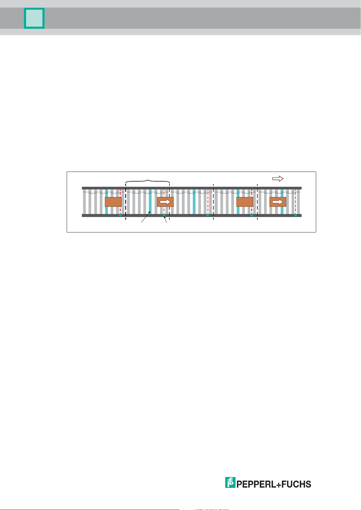
Zero Pressure Accumulation (ZPA)
During zero pressure accumulation, conveyed product is moved along a conveyor line in a
controlled manner and collisions between the conveyed product is prevented. For this purpose,
a conveyor line is divided into several sections or zones.
Each zone has its own drive, which can be activated independently of the neighboring zones.
At the end of each zone, a zone sensor is installed that detects the conveyed product.
The accumulation conveyor logic ensures that there is only ever one conveyed product present
in a zone. Conveyed products can therefore only be conveyed to the downstream zone once
there is no more conveyed product in that zone. As long as the downstream zone is occupied,
the conveyed product is stopped when it reaches the zone sensor and thus accumulates
irrespective of subsequent conveyed product.
Figure 2.1 Conveying scenario for the example Standard ZPA operation mode
Benefits and Features of the ZPA Motor Control Module
The ZPA motor control module is easy to install and can be configured for a wide range of
application situations. The main benefits and features of this m odule are:
■
Compact housing for direct mounting in support profiles and cable ducts.
■
Connection of the power supply using piercing technology via black AS-Interface flat
cable.
■
All other connections are implemented as connectors.
■
Decentralized control: The field module contains the logic for zero pressure accumulation.
A central control unit for the accumulation conveyor line is not required.
■
Support for master-slave operation
■
Control of two successive zones of an accumulation conveyor line using one module.
■
Simple adjustment of the operating mode, the conveyor direction, the motor speed, and
start/stop ramps via rotary switches.
■
Display of status and diagnostic information via LEDs.
■
Optimized for operation with DC roller motors type Interroll EC310.
■
Support for conveyed product that is longer than one zone.
■
Detection of accumulations leads to shutdown of the DC roller motors.
8
2018-06
Page 9
VAZ-2E2A-G20-ZPA1
X1 X2
IN1
MOT1
IN2
MOT2
PWR
X1 IN
X1 OUT
X2 IN
X2 OUT
MOT1
MOT2
ERR1
ERR2
IN1
IN2
IN
OUT
OUT
X2 X2X1X1
IN
OUT
IN
OUT
OUT
IN
OUT
IN
IN
OUT
IN
OUT
MOT1 MOT2 IN2 MOT2 IN2MOT1 IN1
IN
ZoneUpstream
zone
Downstream
zone
Roller motor Roller motor Zone sensor Roller motor Zone sensor
Conveying direction
Roller motor Zone sensor
Release
Sensor
Zone coupling
Sensor Sensor
Release Release
ZPA motor control module
Zone coupling Zone coupling
2 zones
ZPA motor control module
1 zone
Release
Sensor
Zone Zone ZoneZone
Product Description
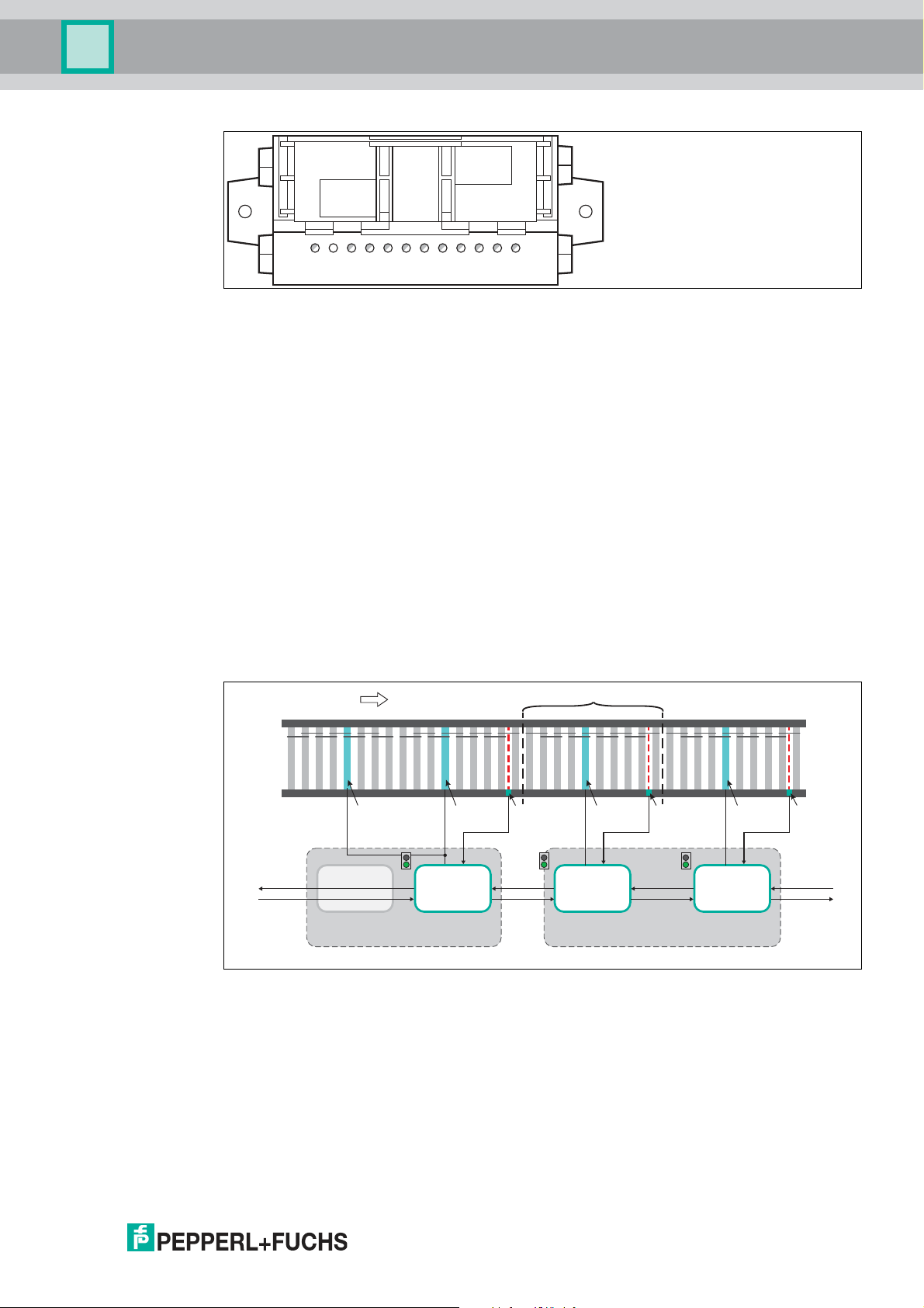
Figure 2.2
Function of the ZPA Motor Control Module
The ZPA motor control module is an intelligent field module that already contains the logic for
zero pressure accumu lation. It assumes the control of one or two consecutive zones powered
by DC roller motors. The m otors (MOT1, MOT2) and zone sensors (IN1, IN2) are connected
directly with the ZPA motor control module for this purpose.
The ZPA motor control module has two separate zone controls. Both zone controls are logically
coupled w ithin the module. The access-side zone control can be deactivated within the
module, so that the outgoing-side zone control controls both DC roller motors as the master.
Only the sensor input (IN1 and IN2) of the master is evaluated in this case.
A coupling with the neighboring zones is created via two interfaces for the zone coupling (X1,
X2). This makes it possible to connect several ZPA motor control modules in series to create an
accumulation conveyor line of any length.
The ZPA motor control module is powered via the black AS-Interface flat cable, which is
connected using piercing technology without the need for tools. The ZPA motor control module
is configured directly on the device using the three rotary switches (S1, S2, S3). In addition to
various operating modes, the motor speed, the conveyor direction, and start and stop ramps
can be configured.
2018-06
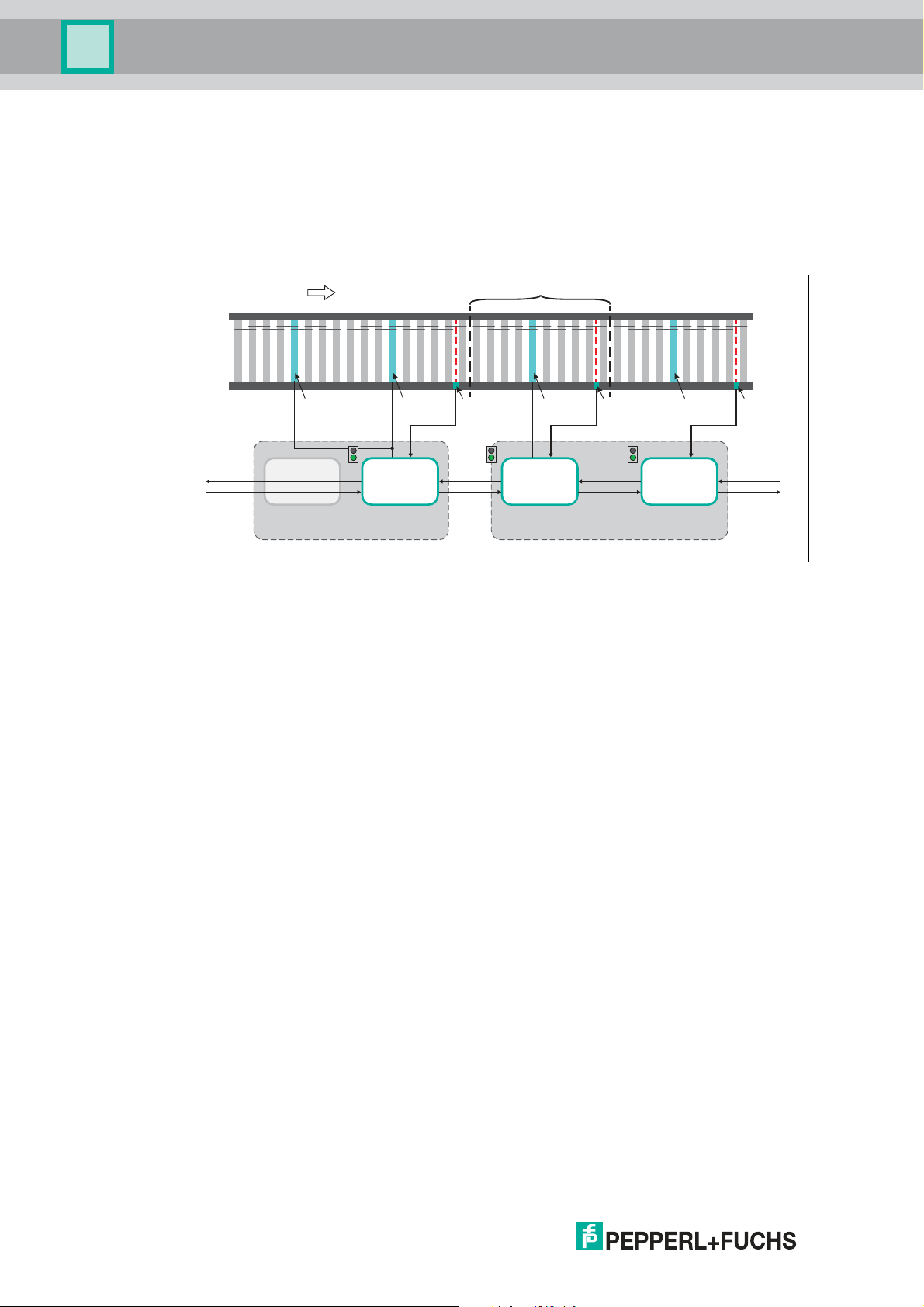
Figure 2.3
1-zone Operation/2-zone Operation
If the ZPA motor control module is to only control a single zone, the second zone logic must be
manually deactivated in some operating modes. For this purpose, the rear zone in the conveyor
direction is bypassed internally. The DC roller motor of this zone then runs synchronous to that
of the zone in front (see previous figure). It can therefore support the other DC roller motor by
driving the same zone and thereby doubling the drive power of that zone.
9
Page 10
VAZ-2E2A-G20-ZPA1
IN
OUT
OUT
X2 X2X1X1
IN
OUT
IN
OUT
OUT
IN
OUT
IN
IN
OUT
IN
OUT
MOT1 MOT2 IN2 MOT2 IN2MOT1 IN1
IN
ZoneUpstream
zone
Downstream
zone
Roller motor Roller motor Zone sensor Roller motor Zone sensor
Conveying direction
Roller motor Zone sensor
Release
Sensor
Zone coupling
Sensor Sensor
Release Release
ZPA motor control module
Zone coupling Zone coupling
2 zones
ZPA motor control module
1 zone
Release
Sensor
Zone Zone ZoneZone
Product Description
Zone coupling
The two interfaces for zone coupling (X1, X2) are used for receiving and transmitting
information to and from neighboring zones. Additional ZPA motor control modules or other
suitable communication partners can be connected via the zone coupling. The electrical
signals are compatible with the standard 24 V IOs of a PLC. Conveyed product can therefore
also be fed in and discharged at both ends of the accumu lation conveyor line by a separate
controller.
Figure 2.4
The interfaces for the zone coupling each consist of one signal input and one signal output.
The meaning of the zone coupling signals depends on the selected conveyor direction and
follows a simple principle:
Signal in the conveyor direction (zone sensor): A zone is communicating to the
downstream zone whether conveyed product is located at its end. It therefore always
corresponds to the signal of the zone sensor (e.g., light barrier).
Signal against the conveyor direction (release signal): A zone is communicating to the
upstream zone whether conveyed product may enter. It thus represents the release signal. The
release signal is determined by the accumulation conveyor logic and also set if no conveyed
product has yet reached the zone sensor of the upstream zone.
The logic in the ZPA motor control modules expects the release signal to last until the conveyed
product has left the zone sensor. If the release signal is withdrawn before the conveyed product
has left the zone, the m otor is stopped until the release signal is set again.
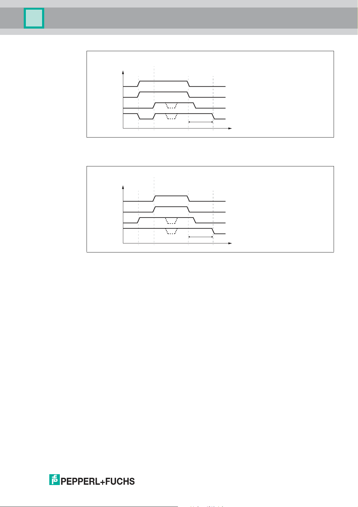
This results in the following signal sequences:
The dashed lines show the situation in which the downstream zone withdraws the release
signal for a short period of time. In this case, the DC roller motor is stopped immediately without
any run-on time.
1. Conveyed product reaches the zone sensor before the release signal is set.
10
2018-06
Page 11
VAZ-2E2A-G20-ZPA1
IN (Photo eye)
X OUT
X IN (Release)
MOT
Motor after run
Conveyor good
has left zone
Release from
downstream zone
Conveyor good
is stopped
to downstream zone
from downstream zone
Motor after run
Conveyor good
has left zone
Release from
downstream zone
Conveyor good reaches zone sensor
IN (Photo eye)
X OUT
X IN (Release)
MOT
to downstream zone
from downstream zone
Product Description
Figure 2.5
2. Release signal is set before the conveyed product reaches the zone sensor.
Figure 2.6
Since the ZPA motor control module can control two consecutive zones simultaneously, the
zone coupling of these two zones is performed internally. The zone coupling to the upstream
and downstream zones is routed via connections X1 and X2.
2.2 Operating Modes of the ZPA Motor Control Module
2.2.1 Overview
The ZPA motor control module has multiple operating modes that realize different
accumulation conveyor logics. All operate zone coupling as per the preceding description and
are therefore fully compatible with each other. The only exception to this rule are the two
operating modes "direct control" and "direction control." These operating modes do not
execute logic and a re used for direct control of the connected DC roller motors via the zone
coupling interfaces.
For the operation of only one zone, the mode for 1-zone operation must be selected in the case
of some operating modes. Different time conditions detect accumulations on the conveyor line
and shut down the DC roller motors if one or more conveyed products are stuck. All operating
modes support the handling of conveyed product that is longer than the actual zone.
2018-06
11
Page 12
VAZ-2E2A-G20-ZPA1
5 64
B
2 31
A
8 97
C
Roller motor
Zone sensor Zone sensor
Roller motor
Zone sensor Zone sensor
Roller motor
Zone sensor Zone sensor
Product Description
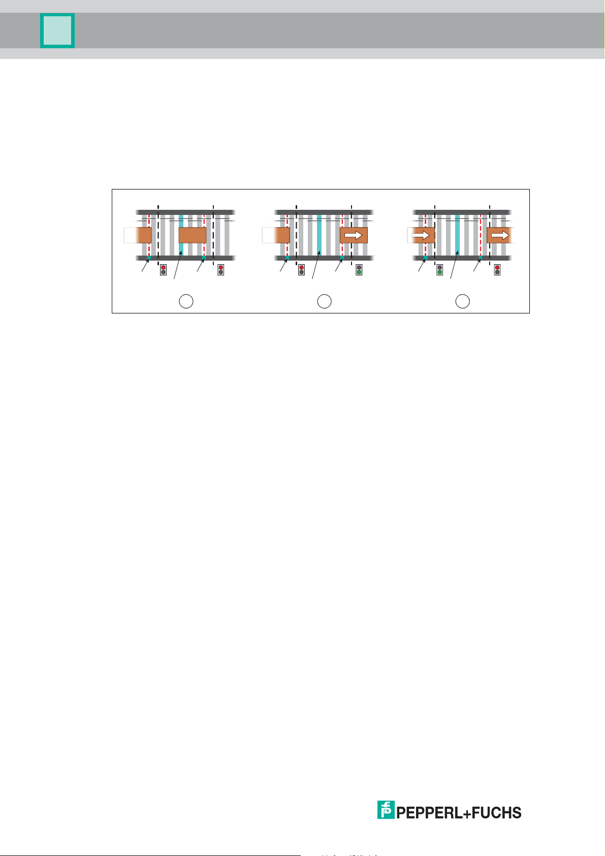
2.2.2 Standard ZPA
Conveyed product must have completely left the zone before the next conveyed product may
enter. As soon as the outgoing conveyed product is no longer detected by the zone sensor, the
release signal is set. This operating mode thereby realizes zero pressure accumulation with
single accumulation and single release. It ensures a strict separation of the conveyed product
while maintaining the maximum safety distance.
The following example describes the sequence in the operating mode "Standard ZPA":
Figure 2.7
■
Step A: Zone (2) has accumulated its conveyed product because downstream zone (3)
has not set its release signal (red light). Because zone (2) is occupied, it also does not
issue a release to upstream zone (1).
■
Step B: Downstream zone (6) has set the release signal (green light) and the conveyed
product is conveyed to the next zone (6). Because the conveyed product has not yet left
the zone sensor (5), zone (5) does not issue a release to upstream zone (4).
■
Step C: The conveyed product has left the zone sensor. Therefore, zone (8) sets the
release signal for upstream zone (7) to allow the next conveyed product to be transported.
Downstream zone (9) has now completely accepted the conveyed product and prohibits
further produ ct from entering by withdrawing the release.
The following time conditions are used in the operating mode "Standard ZPA" (see Chapter
"Operating Behavior"):
■
Leaving time
■
Entry time
■
Transportation time
■
Motor run-on time
■
Switch-on delay
■
Search time
Please note that this operating mode distinguishes between 1-zone operation and 2-zone
operation and separate settings exist for both operating modes.
12
2018-06
Page 13
VAZ-2E2A-G20-ZPA1
5 64
B
2 31
A
8 97
C
Roller motor
Zone sensor Zone sensor
Roller motor
Zone sensor Zone sensor
Roller motor
Zone sensor Zone sensor
Product Description
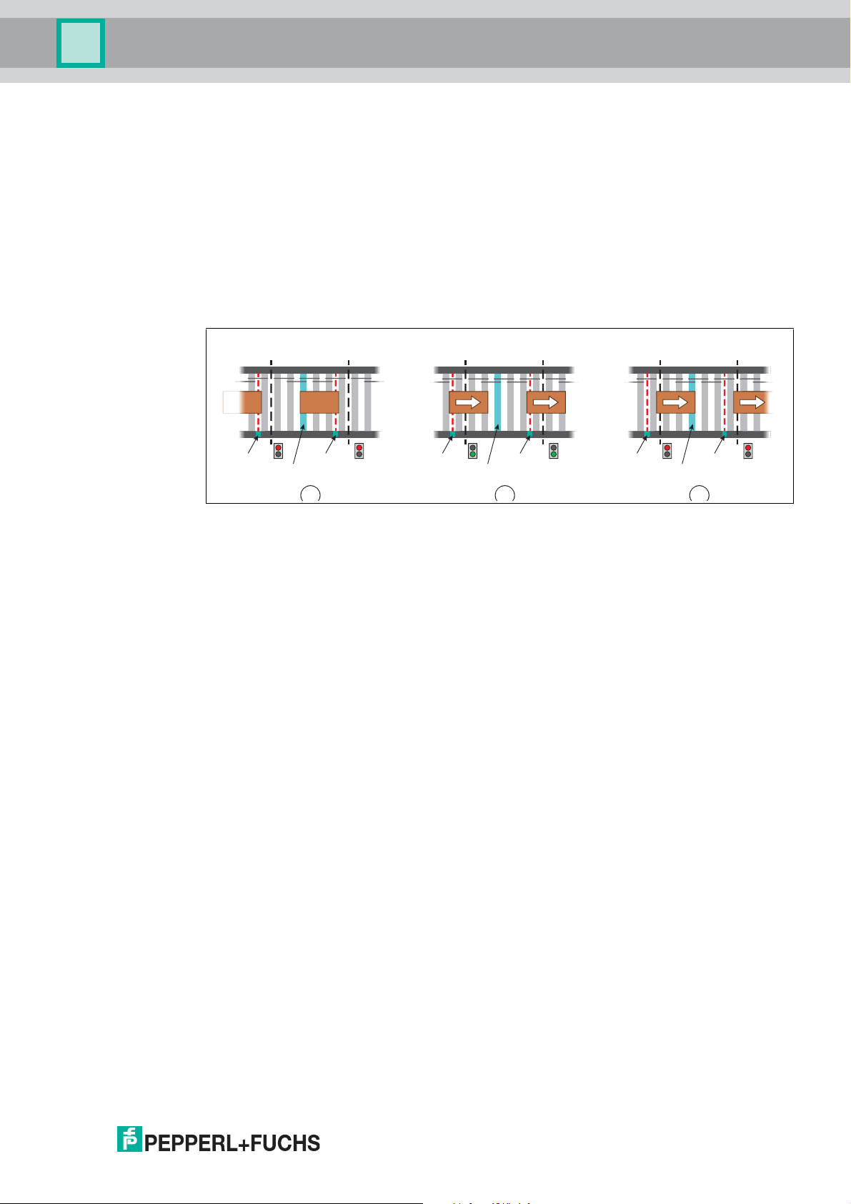
2.2.3 Enhanced ZPA
This operating mode implements zero pressure accumulation with block accumulation or block
release. A zone will let the following conveyed product enter once the conveyed product
located in that zone receives the release signal to leave the zone. This reduces the safety
distance between the conveyed product and increases the throughput. If the foremost zone of
such an accum ulation conveyor line receives a release signal, the signal will be forwarded
directly to the zones behind it. All accumulated conveyed product will be simultaneously
transported to the next zone. However, in case of block release, it is always ensured that only
one further conveyed product is conveyed into the zone. This conveyed product must then
advance all the way to the zone sensor before the next conveyed product may be conveyed.
The following example describes the sequence in the operating mode "Enhanced ZPA."
Figure 2.8
■
Step A: Zone (2) has accumulated its conveyed product because downstream zone (3)
has not set its release signal (red light). Because zone (2) is occupied, it also does not
issue a release to upstream zone (1).
■
Step B: Downstream zone (6) has set the release signal (green light) and the conveyed
product is conveyed to the next zone (6). At the same time, the release signal is forwarded
to upstream zone (4) and the following conveyed product is conveyed to zone (5). The
conveyed product starts up at the same time.
■
Step C: The previous conveyed product has departed zone (8), so downstream zone (9)
withdraws its release. The following conveyed product has also already left upstream
zone (7). Zone (8) moves the conveyed product to its zone sensor while it prevents other
conveyed product from entering by resetting the release.
The following time conditions are used in the operating mode "Enhanced ZPA" (see Chapter
"Operating Behavior"):
■
Leaving time
■
Entry time
■
Transportation time
■
Motor run-on time
■
Switch-on delay
■
Search time
2018-06
■
Release delay
Please note that this operating mode distinguishes between 1-zone operation and 2-zone
operation and separate settings exist for both operating modes.
13
Page 14

VAZ-2E2A-G20-ZPA1
5 64
B
2 31
A
8 97
C
Roller motorRoller motor Roller motor
Product Description
2.2.4 Transportation
In this operating mode, a zone forwards the release signal directly to the zones behind it. At the
same time, the release signal also switches on the zone motor. The release is not set
independently. Therefore, only a block release is carried out, which does not cause the
conveyed product to be separated.
Connecting a zone sensor is optional in this operating mode. If a zone sensor is connected, the
logic can detect accumulations and shut down the zone DC roller motor, if necessary. If the
downstream zone is operating in a different mode, the zone sensor must be connected so that
its status can be forwarded via the zone coupling.
The following example describes the sequence in the operating mode "Transportation":
Figure 2.9
■
Step A: Downstream zone (3) has not set its release signal (red light). Zone (2) therefore
also does not set its release signal, meaning that the DC roller motor does not rotate.
■
Step B: Downstream zone (6) has set the release signal (green light). Zone (5)
immediately forwards the release signal to its upstream zone (4) and switches on its DC
roller motor. The conveyed product starts up at the same time.
■
Step C: Downstream zone (9) has reset its release signal. Zone (8) immediately resets its
release signal and shuts down the DC roller motor.
The following time condition is used in the operating mode "Transportation" (see Chapter
"Operating Behavior"):
■
Leaving time (only if a zone sensor is connected)
This operating m ode can be used without restriction in 1-zone and 2-zone operation. For this
reason, there is no option for a separate switchover.
14
2018-06
Page 15

VAZ-2E2A-G20-ZPA1
5 64
B
2 31
A
8 97
C
Roller motor
Zone sensor Zone sensor
Roller motor
Zone sensor Zone sensor
Roller motor
Zone sensor Zone sensor
Product Description
2.2.5 Long Zone - Single Zone
This operating mode is designed specifically for the operation of a zone in a range of Standard
zones or Enhanced ZPA zones that is significantly longer than the surrounding zones. A longer
zone like this would negatively affect the throughput of the entire conveyor line because the
distance between the conveyed product is primarily determined by the zone length. This is why
conveyed product is not separated in this case, which m ight cause the distance between the
conveyed product to increase.
If there is a release signal, it is forwarded directly to the zones behind that zone and the DC
roller motor of the zone is switched on (block release). If there is no conveyed product in front of
the zone sensor, the zone will independently set the release signal to allow more conveyed
product to enter. If no conveyed product has been detected for a certain period of time, the
zone will shut down its DC roller motor. It will start its DC roller motor again if the status of the
upstream zone sensor changes and conveyed product is conveyed into the zone.
The following example describes the sequence in the operating mode "Long Zone":
Figure 2.10
■
Step A: Downstream zone (3) has set its release signal (green light). Zone (2) immediately
forwards it to its upstream zone (1) and conveys its conveyed produ ct to the next zone (3).
■
Step B: Downstream zone (6) has reset its release signal (red light). Because no product
has arrived in front of the zone sensor in zone (5) yet, it will retain its release and move the
conveyed product to its final position. The subsequent conveyed product (4) can enter
freely.
■
Step C: The conveyed product has reached the zone sensor (8). Because the
downstream zone (9) is still not issuing a release signal, zone (7) stops the conveyed
product and resets its release signal to also stop the subsequent conveyed product.
The following time conditions are used in the operating mode "Long Zone" (see Chapter
"Operating Behavior"):
■
Leaving time
■
Switch-on delay
■
Idle mode delay
This operating mode always works in 1-zone operation, meaning that the DC roller motor of the
rear zone is synchronized with that of the front zone and the rear zone sensor has no function.
2018-06
15
Page 16

VAZ-2E2A-G20-ZPA1
Product Description
2.2.6 Direct Control
In this operating mode, the DC roller motors connected to the ZPA motor control module can be
controlled using external signals. In this way, the ZPA control module can, for example, be
connected directly to a PLC that follows its own logic for controlling the DC roller motors. The
control signals are transferred via the inputs of the respective zone coupling inter faces. The
outputs of the two zone coupling interfaces indicate the status of the zone sensors.
Connection Signal Meaning
X1 IN Control signal for DC roller m otor at MOT1
X1 OUT Signal for zone sensor at IN1
X2 IN Control signal for DC roller m otor at MOT2
X2 OUT Signal of zone sensor at IN2
Table 2.1
■
Low: Motor is at a standstill
■
High: Motor is running
■
Low: No conveyed product detected
■
High: Conveyed product detected
■
Low: Motor is at a standstill
■
High: Motor is running
■
Low: No conveyed product detected
■
High: Conveyed product detected
2.2.7 Direction Control
This operating m ode supplements the "Direct Control" operating mode with the option of
reversing the direction of rotation of the connected DC roller motors via an external signal. One
input controls both DC motor rollers while the other input reverses their configured direction of
rotation.
The "Direction Control" operating m ode will be supported from firmware version V.26.
Connection Signal Meaning
X1 IN Control signal for DC roller m otors at MOT1 and MOT2
X1 OUT Signal for zone sensor at IN1
X2 IN Direction reversal for DC roller m otors at MOT1 and
X2 OUT Signal of zone sensor at IN2
Table 2.2
■
Low: Motor is at a standstill
■
High: Motor is running
■
Low: No conveyed product detected
■
High: Conveyed product detected
MOT2
■
Low: Motors rotate in the direction configured via S2
■
High: Motors rotate in the opposite direction to that
configured via S2
■
Low: No conveyed product detected
■
High: Conveyed product detected
16
2018-06
Page 17

VAZ-2E2A-G20-ZPA1
X2 X1X1
OUT
IN
OUT
IN
MOT MOT MOT1 IN1
X2
IN
OUT
IN
OUT
MOT2 IN2
MasterSlave 1 ... n
OUT
MOT
2
Roller motor Roller motor Roller motor
Master-slave zone
Conveyor direction
Release
Sensor
Zone coupling Zone coupling
Zone
Roller motor Zone sensor
Zone
Product Description
2.2.8 Slave
In this operating mode, the ZPA motor control module functions as a slave to a downstream
master zone. Both slave motors are synchronized to the master zone motors. The master zone
is extended by the slave. The signals from the rear zone coupling of the master are transmitted
by the slave through to the upstream zone. The zone sensors of the slaves have no function in
this operating mode and do not need to be connected.
As the master, all of the ZPA motor control module operating modes can be used, except for
"Direct Control" and "Direction Control." No special settings are required at the master. As soon
as the upstream ZPA motor control module has been configured as a slave, the switchover to
master operation occurs automatically.
Any number of slaves can be run on a master zone. Each slave corresponds to a ZPA motor
control module. The zone length, which is controlled by the master, is extended by the
connected slaves. The following time conditions for the master and the connected slaves are
added up. Up to four slaves can be taken into account.
1. Search time
2. Transportation time
3. Idle mode delay
2018-06
Figure 2.11
Please note that the zone couplings between master and slave work in master-slave operation.
There, there are no PLC-compatible zone coupling signals. If the zone coupling of a slave has
not been connected to a compatible master, the corresponding LED flashes "X1 IN" or "X2 IN"
and the ZPA motor control module has no function.
The "Slave" operating mode is supported from firmware version V.28 (master and slave).
17
Page 18

VAZ-2E2A-G20-ZPA1
X1 X2
IN1
MOT1
IN2
MOT2
PWR
X1 IN
X1 OUT
X2 IN
X2 OUT
MOT1
MOT2
ERR1
ERR2
IN1
IN2
Product Description
2.3 Indicators and Operating Elements
2.3.1 LED Indicators
Overview
The LEDs on the ZPA motor control module display the following information:
■
Firmware version (only immediately after switching on),
■
Setting of the rotary switch (only immediately after switching on),
■
Status of the power supply,
■
Switching states of the connected zone sensors,
■
Operating/fault state of the connected DC roller motors,
■
States of the zone coupling signals.
While the ZPA motor control module is starting up, the LEDs indicate the firmware version and
the setting of the rotary switches using flash codes (binary code; least significant byte is on the
right).
The meaning of the individual zone coupling signals depends on the conveyor direction and
how the ZPA motor control module is connected. (See Chapter "Use and Application", Section
"Zone Coupling").
Figure 2.12
LED Behavior after Switch-On
In case of an invalid configuration or an invalid operating mode, the four left LEDs X1 ...X2 OUT
will flash simultaneously.
While the ZPA motor control module is starting up, the LEDs indicate the firmware version and
the setting of the rotary switches S1 ... S3 in four steps using flash codes. The LEDs provide
the information in binary form. The least significant byte is on the right.
The two left LEDs X1 IN and X1 OUT indicate the respective step from 0 ... 3. The steps
designate the type of information.
The remaining LEDs indicate the corresponding values for the steps, such as the setting of a
rotary switch.
Each step is displayed for 1 s. After 4 s, all the steps have been displayed.
Step Information displayed
0 Firmware version
1 S1 setting: Motor speed
2 S2 setting: Start/stop ramp and direction of rotation
3 S3 setting: Operating mode
18
2018-06
Page 19

VAZ-2E2A-G20-ZPA1
Product Description
Note!
Motor Fuses Are Safety Fuses
For protection against short circuits, each DC roller motor is secured with its own safety fuse
with a 5 A rated current. The fuses are not interchangeable. If a fuse is faulty, the module must
be replaced.
LEDs for PWR, MOT1, MOT2, ERR1, ERR2, IN1, IN2
LED Color Description
PWR Green
MOT1 Yellow Operating status of DC roller motor 1:
MOT2 Yellow Operating status of DC roller motor 2:
■
On = Power supply is OK
■
Off = Power supply is not OK
■
On = Motor is active
■
Off = Motor is at a standstill or running down as per set start/stop
ramp
■
On = Motor is active
■
Off = Motor is at a standstill or running down as per set start/stop
ramp
ERR1 Yellow Fault status of DC roller motor 1:
■
On = Motor fault or no motor connected
■
Flashing = Motor fuse 1 of the motor control module is faulty
■
Off = No motor fault
ERR2 Yellow Fault status of DC roller motor 2:
■
On = Motor fault or no motor connected
■
Flashing = Motor fuse 2 of the motor control module is faulty
■
Off = No motor fault
IN1 Switch state of zone sensor 1:
■
On = Zone sensor has detected conveyed product (high level)
■
Off = Zone sensor has not detected any conveyed product (low
level)
IN2 Switch state of zone sensor 2:
■
On = Zone sensor has detected conveyed product (high level)
■
Off = Zone sensor has not detected any conveyed product (low
level)
Table 2.3
Status LEDs for zone coupling: Conveyor direction from left to right
LED Color Description
X1 IN Yellow Input from interface 1: Status of zone sensor of upstream zone
■
On = Zone sensor has detected conveyed product (high level)
■
Off = Zone sensor has not detected any conveyed product (low
level)
X1 OUT Yellow Output from interface 1: Release signal for upstream zone
■
On = Release signal for upstream zone has been set (high level)
■
Off = Release signal for upstream zone has not been set (low
level)
2018-06
19
Page 20

VAZ-2E2A-G20-ZPA1
Product Description
LED Color Description
X2 IN Yellow Input from interface 2: Release signal from downstream zone
X2 OUT Yellow Output from interface 2: Status of zone sensor at IN2
Table 2.4
Status LEDs for zone coupling: Conveyor direction from right to left
LED Color Description
X1 IN Yellow Input from interface 1: Release signal from downstream zone
■
On = Release signal from downstream zone has been set (high
level)
■
Off = Release signal from downstream zone has not been set (low
level)
■
On = Zone sensor has detected conveyed product (high level)
■
Off = Zone sensor has not detected any conveyed product (low
level)
■
On = Release signal from downstream zone has been set (high
level)
■
Off = Release signal from downstream zone has not been set (low
level)
X1 OUT Yellow Output from interface 1: Status of zone sensor at IN1
■
On = Zone sensor has detected conveyed product (high level)
■
Off = Zone sensor has not detected any conveyed product (low
level)
X2 IN Yellow Input from interface 2: Status of zone sensor of upstream zone
■
On = Zone sensor has detected conveyed product (high level)
■
Off = Zone sensor has not detected any conveyed product (low
level)
X2 OUT Yellow Output from interface 2: Release signal for upstream zone
■
On = Release signal for upstream zone has been set (high level)
■
Off = Release signal for upstream zone has not been set (low
level)
Table 2.5
20
2018-06
Page 21

VAZ-2E2A-G20-ZPA1
1
2
3
4
5
6
7
8
9
0
1
2
3
4
5
6
7
8
9
0
1
2
3
4
5
6
7
8
9
0
S3 S2 S1
Product Description
2.3.2 Rotary Switches for Configuration
On the back of the device, there are three rotary switches for configuring
■
Motor speed via S1
■
Start/stop ramp and direction of rotation via S2
■
Operating mode via S3
Figure 2.13
Note!
Configuration Requires the Power Supply to Be Switched Off/On
The settings of the rotary switches are applied when the ZPA motor control module is switched
on. When a change is m ade to the configuration, you will need to shut down the power supply
to the ZPA motor control module and then switch it on again.
S1: Motor speed
Switch setting
Speed signal U
s
0 3.96 V
1 4.78 V
2 5.61 V
3 6.44 V
4 8.50 V
5 9.63 V
6 10.00 V
7 7.26 V
8 Reserved
9 Reserved
Table 2.6
S2: Start/stop ramp and direction of rotation
You can use rotary switch S2 to set the direction of rotation of the connected DC roller motors
(conveyor direction) and configure a start/stop ramp for the acceleration at the same time.
Five start/stop ramps can be configured for each direction of rotation. The slope of the
acceleration is constant and independent of the set maximum speed.
The ramp duration defines the time from stationary to maximum speed (US = 10 V), or from
maximum speed to stationary. When the set motor speed is lower, the ram p duration is shorter
as well.
The following diagram shows the start behavior of the start/stop ramp using the example of the
setting "1000 ms."
2018-06
21
Page 22

VAZ-2E2A-G20-ZPA1
100
75
50
25
200 400 600 800 1000
Speed [%]
Time [ms]
Speed 100%
Speed 60%
acceleration
time setting
Product Description
Figure 2.14
The direction of rotation setting defines not only the direction of rotation of the connected DC
roller motors but also which of the two zones is the "downstream zone" and which is the
"upstream zone." In this way, the conveyor direction is also defined.
For clockwise direction of rotation, the left zone (IN1, MOT1) is the "upstream zone."
For counterclockwise direction of rotation, the right zone (IN2, MOT2) is the "upstream zone."
■
Switch position 0 ... 5: Clockwise direction of rotation (conveyor direction from left to right),
UD = High
22
■
Switch position 6 ... 9: Counterclockwise direction of rotation (conveyor direction from
right to left), UD = Low
Switch setting Ramp duration Direction of rotation
0 0 ms clockwise
1 500 ms clockwise
2 1000 ms clockwise
3 1500 ms clockwise
4 3000 ms clockwise
5 0 ms counterclockwise
6 500 ms counterclockwise
7 1000 ms counterclockwise
8 1500 ms counterclockwise
9 3000 ms counterclockwise
S3: Operating mode
Depending on the application, you can select one of eight different operating modes for 1-zone
control or 2-zone control. For 1-zone control (Single Zone), the inactive zone synchronizes its
motor output with the active zone.
Switch setting Operation Mode 1-/2-zone operation
0 Standard ZPA 2-zone operation
1 Enhanced ZPA 2-zone operation
2 Standard ZPA—Single
Zone
3 Enhanced ZPA—Single
Zone
4 Transportation 1-zone operation and 2-zone operation
5 Long Zone—Single Zone 1-zone operation
6 Direct Control 1-zone operation and 2-zone operation
7 Direction Control 1-zone operation
1-zone operation
1-zone operation
2018-06
Page 23

VAZ-2E2A-G20-ZPA1
BLACK
PWR
+
-
3 1
4 2
3 1
4 2
5
Product Description
Switch setting Operation Mode 1-/2-zone operation
8 Slave 1-zone operation
9 Reserved -
Table 2.7
2.4 Interfaces and Connections
Connections: Inputs/Outputs
The sensors and motors are connected to the ZPA motor control module via cables with round
M8 connectors:
■
Sensors: socket, 4-pin
■
Motors: socket, 5-pin
The signals for zone coupling are connected to the ZPA motor control module via cables with
round M12 connectors.
The exact meaning of the inputs and outputs of the signals for zone coupling depends on the
connection of the ZPA motor control m odule (see Chapter "Use and Application," Section
"Zone Coupling").
Power Supply
The power supply of the ZPA motor control module is provided using piercing technology with
an AS-Interface flat cable via the PWR contacts of the ZPA motor control module.
Connector Assignment
Connection Connector Connector type/assignment
PWR Power supply: black AS-Interface flat cable
(2 x 1.5 m m2)
Two pins for piercing technology
-: Negative power supply pole
+: Positive power supply pole
IN1, IN2: sensor Input: LF004-GS1-A in accordance with
MOT1, MOT2: motor Motor: NF005-SS1-B in accordance with
IEC/EN 61076-2-104
M8, 4-pin, socket, cap nut, coding A
Matching female connector: LM004-Gx1-A
or similar
1: IN+ sensor supply
2: Not used
3: IN- sensor supply GND
4: IN sensor signal
IEC/EN 61076-2-104
M8, 5-pin, socket, snap-locking, coding B
Matching female connector: NM005-Sx1-B
or similar
1: MOT+ motor supply
2: DIR direction of rotation
3: MOT- motor supply GND
4: ERROR input for motor fault
5: SPEED speed signal (default value)
2018-06
23
Page 24

VAZ-2E2A-G20-ZPA1
1
5
3
2
4
1
3
4
2
Product Description
Connection Connector Connector type/assignment
X1: Zone coupling,
interface 1
X1 Zone coupling M12 round plug connector
in accordance with IEC/EN 61076-1-101
M12, 4-pin, socket, screw-locking, coding A
1: X1 IN input signal
2: X1 IN- input GND
3: X1 OUT output signal
4: X1 OUT- output GND
5: Not assigned
X2: Zone coupling,
interface 2
X2 Zone coupling M12 round plug connector
in accordance with IEC/EN 61076-1-101
M12, 4-pin, plug, screw-locking, coding A
1: X2 OUT output signal
2: X2 OUT- output GND
3: X2 IN output signal
4: X2 IN- input GND
24
2018-06
Page 25

VAZ-2E2A-G20-ZPA1
X1 X2
IN1
MOT1
IN2
MOT2
PWR
X1 IN
X1 OUT
X2 IN
X2 OUT
MOT1
MOT2
ERR1
ERR2
IN1
IN2
1
2
3
4
5
6
7
8
9
0
1
2
3
4
5
6
7
8
9
0
1
2
3
4
5
6
7
8
9
0
S3 S2 S1
Installation
3 Installation
3.1 Safety Information
Caution!
Risk of short circuit
Carrying out work while the system is energized may result in damage to the device.
■
Always disconnect the supply voltage before carrying out work on the device.
■
Only connect the device to the supply voltage once all work has been completed.
3.2 Preparation
Unpacking the unit
1. Check that all package contents are present and undamaged.
If anything is damaged, inform the shipper and contact the supplier.
2. Check that all items are present and correct based on your order and the shipping
documents.
If you have any questions, please contact Pepperl+Fuchs.
3. Keep the original packing material in case you need to store or ship the unit at a later time.
3.3 Mounting
Note!
Note the Mounting Direction of the ZPA Motor Control Module
The ZPA motor control module is designed to be mounted between two conveyor zones. The
mounting direction is such that the LEDs always point downward and the hinged cable guide
upward. This ensures the correct assignment of the connected zones (right zone -> right-side
connection, left zone -> left-side connection).
Figure 3.1
Set the rotary switches S1...S3 as per their desired application. (see Chapter "Product
Description", Subsection "Indicators and Operating Elements").
24
2018-06
Page 26

VAZ-2E2A-G20-ZPA1
Installation
3.4 Power Supply Connection
The power supply is connected to the ZPA motor control module via a black AS-Interface flat
cable. The permissible supply voltage is 18 V ... 30 V.
The electric connection between the ZPA motor control module and flat cables is established
via two metal pins using piercing technology. The flat cable is routed through a hinged cable
guide. When closed, the cable guide is locked using a locking bracket and can be opened
again without the need for tools.
The profiled flat cable has a narrow upper side (with a visibly offset profile edge) and a wide
under side (profile edge not visible). The cable guide allows the flat cable to be inserted on
both sides, for flexible connection of flat cables already laid in cable ducts. However, you must
make sure that the profile edge always points to the motor control module. Mechanical reverse
polarity protection prevents complete closure of the cable guide if the flat cable is inserted
incorrectly.
Caution!
If a flat cable is inserted incorrectly, the ZPA motor control module will not work.
If the flat cable is inserted in the cable guide in the wrong direction, the voltage is inverted. The
ZPA motor control module will not work. However, internal electrical reverse polarity protection
protects it against breakage.
Connecting Flat Cables on the Narrow Side
The profile edge is visible from above.
1. O pen the cable guide. To do this, push the locking bra cket (1) slightly to one side.
2. Insert the black flat cable with the profile edge (2) to the ZPA motor control module into the
upper duct (see module tag "PWR").
3. Make sure that the profile edge of the flat cable is under the respective reverse polarity
protection (3).
4. C lose the cable guide. It must engage securely in the locking bracket (1).
The metal pins contact the cores of the flat cable.
2018-06
25
Page 27

VAZ-2E2A-G20-ZPA1
PWR
1
2
3
Installation
Figure 3.2 Connecting flat cables on the narrow side
Connecting Flat Cables on the Wide Side
The profile edge is not visible from above. For orientation purposes in the figure below, the
edge is shown as a hidden edge drawn with a dotted line.
1. Open the cable guide. To do this, push the locking bracket (1) slightly to one side.
2. Insert the black flat cable with the profile edge (2) to the ZPA motor control module into the
upper duct (see module tag "PWR").
The profile edge (2) of the flat cable is above the reverse polarity protection.
3. Close the cable guide. It must engage securely in the locking bracket (1).
The metal pins contact the cores of the flat cable.
26
2018-06
Page 28

VAZ-2E2A-G20-ZPA1
PWR
1
2
Installation
Figure 3.3 Connecting flat cables on the wide side (profile edge as dotted lin e)
Flat Cable Inserted Incorrectly
The figure below shows an incorrectly inserted flat cable. The profile edge (2) does not point to
the motor control module; the flat cable is therefore inserted with reverse polarity. The flat cable
is located on the reverse polarity protection (1) with a curvature, which means that the cable
guide cannot be closed completely (mechanical reverse polarity protection).
2018-06
27
Page 29

VAZ-2E2A-G20-ZPA1
1
2
X1 X2
IN1
MOT1
IN2
MOT2
PWR
X1 IN
X1 OUT
X2 IN
X2 OUT
MOT1
MOT2
ERR1
ERR2
IN1
IN2
Installation
Figure 3.4 Flat cable inserted incorrectly (profile edge as dotted lin e)
3.5 Special Requirements when Connecting to a PLC
The electrical signals from the zone coupling interfaces are compatible with the standard 24 V
IOs of a P LC.
■
The inputs (X1 IN, X2 IN) are galvanically isolated. Therefore, there are no special
requirements for the connection of other potentials.
■
The outputs (X1 OUT, X2 OUT) are powered directly by the power supply of the ZPA
motor control module. Therefore, there is a risk of ground loops when connecting to other
potentials
Caution!
Malfunctions with ground loops
Because the outputs of the ZPA motor control module are not galvanically isolated,
equalization currents could flow through their ground lines. Therefore, connect the zone
coupling outputs (X1 OUT, X2 OUT) only to galvanically isolated, current-consuming inputs of a
PLC input/output card.
A common ground of the PLC input/output card may be connected to other ZPA motor control
modules, but not to their power supply.
If the specified rules are not followed, malfunctions may occur in the interconnected
components.
3.6 Connecting Motors, Sensors, and Zone Coupling
Figure 3.5
28
2018-06
Page 30

VAZ-2E2A-G20-ZPA1
(n.c.)
PWR +
IN1 & IN2
MOT1 & MOT2
3 1
4 2
M
3 1
4 2
5
ERR1,2
PWR
PWR -
IN1,2
1
4
3
2
1
2
4
5
3
MOT1,2
IN +
IN
IN -
MOT +
DIR
ERROR
SPEED
MOT -
X1OUT
X1IN
1
2
3
4
X1IN
X1IN X1OUT
X1OUT -
3
4
1
2
X2IN
X2IN X2OUT
X2OUT -
ZPA1
PLC
ZPA1
PLC
3
1
4 2
3
1
2 4
X2OUT
X2IN
X1
X2
Installation
Note!
The connection of DC roller motors and zone sensors to the ZPA motor control module
depends on the circumstances of the zones to be controlled. There are a variety of connection
scenarios depending on whether you want to control one or two zones or when changing the
mounting side on the conveyor line. These scenarios are described in the following sections.
Figure 3.6 Connection wiring diag ram for motors, sensors, and zone coupling
Note!
Note the Mounting Direction of the ZPA Motor Control Module
The ZPA motor control module is designed to be mounted between two conveyor zones. The
mounting direction is such that the LEDs always point downward and the hinged cable guide
upward. This ensures the correct assignment of the connected zones (right zone -> right-side
connection, left zone -> left-side connection). The mounting side on the conveyor line may
need to be changed due to curves or structural restrictions. In this case, special adapter cables
are required that cross the signal lines. (See Accessories section of datasheet). When
changing the m ounting side, the direction of rotation at S2 m ust also be changed.
Standard Connection of the ZPA Motor Control Module (2-Zone
Operation)
The ZPA motor control module is designed to control two consecutive zones.
The ZPA motor control module is mounted between the two zones. The connection lines of the
DC roller motors and zone sensors are connected to the respective side of the ZPA motor
control module near the zone.
The zone coupling signals are connected to the ZPA motor control modules or other
communication partners of the zone upstream and downstream of the two control zones (Zone
1, Zone 2).
2018-06
29
Page 31

VAZ-2E2A-G20-ZPA1
Switch S2 = 0..4 (CW)
Zone 1 Zone 2Upstream zone
Downstream zone
X2
MOT1 MOT2
IN1
IN2
X1
PWR
X1IN
X1 OUT
X2 IN
X2 OUT
MOT1
MOT2
ERR1
ERR2
IN1
IN2
IN1
MOT1
IN2
MOT2
X1 X2
X2
MOT1 MOT2
IN1 IN2
X1
PWR
X1IN
X1 OUT
X2 IN
X2 OUT
MOT1
MOT2
ERR1
ERR2
IN1
IN2
IN1
MOT1
IN2
MOT2
X1 X2
X2
MOT1 MOT2
IN1 IN2
X1
PWR
X1IN
X1 OUT
X2 IN
X2 OUT
MOT1
MOT2
ERR1
ERR2
IN1
IN2
IN1
MOT1
IN2
MOT2
X1 X2
Switch S2 = 5..9 (CCW)
Zone 1 Zone 2 Upstream zoneDownstream zone
X2
MOT1 MOT2
IN1
IN2
X1
PWR
X1IN
X1 OUT
X2 IN
X2 OUT
MOT1
MOT2
ERR1
ERR2
IN1
IN2
IN1
MOT1
IN2
MOT2
X1 X2
X2
MOT1 MOT2
IN1 IN2
X1
PWR
X1IN
X1 OUT
X2 IN
X2 OUT
MOT1
MOT2
ERR1
ERR2
IN1
IN2
IN1
MOT1
IN2
MOT2
X1 X2
X2
MOT1 MOT2
IN1 IN2
X1
PWR
X1IN
X1 OUT
X2 IN
X2 OUT
MOT1
MOT2
ERR1
ERR2
IN1
IN2
IN1
MOT1
IN2
MOT2
X1 X2
Installation
Conveyor Direction from Left to Right (Clockwise Rotation)
Interface zone coupling Description Behavior
X1 IN Output signal from the zone
X2 OUT Output signal of the zone
X1 OUT Release signal for upstream
X2 IN Release signal from
sensor of the upstream zone
sensor at IN2
zone
downstream zone
■
Low level: No conveyed
product detected
■
High level: Conveyed
product detected
■
Low level: No release
■
High level: Release
Figure 3.7 Conveying direction from left to right (clockwise)
Conveyor Direction from Right to Left (Counterclockwise Rotation)
Interface zone coupling I/O Description Behavior
X2 IN Zone sensor of upstream zone
X1 OUT Output signal of the zone
sensor at IN1
■
Low level: No conveyed
product detected
■
High level: Conveyed
product detected
X1 IN Release signal from
downstream zone
■
Low level: No release
■
High level: Release
X2 OUT Release signal for upstream
zone
30
Figure 3.8 Conveying direction from right to left (counterclockwise)
2018-06
Page 32

VAZ-2E2A-G20-ZPA1
X2
MOT1 MOT2
IN1 IN2
X1
PWR
X1IN
X1 OUT
X2 IN
X2 OUT
MOT1
MOT2
ERR1
ERR2
IN1
IN2
IN1
MOT1
IN2
MOT2
X1 X2
X2
MOT1 MOT2
IN1 IN2
X1
PWR
X1IN
X1 OUT
X2 IN
X2 OUT
MOT1
MOT2
ERR1
ERR2
IN1
IN2
IN1
MOT1
IN2
MOT2
X1 X2
X2
MOT1 MOT2
IN1 IN2
X1
PWR
X1IN
X1 OUT
X2 IN
X2 OUT
MOT1
MOT2
ERR1
ERR2
IN1
IN2
IN1
MOT1
IN2
MOT2
X1 X2
Switch S2 = 0..4 (CW)
ZoneUpstream zone Downstream zone
Single-zone operation
Dual-zone operation
Single-zone operation
X2
MOT1 MOT2
IN1 IN2
X1
PWR
X1IN
X1 OUT
X2 IN
X2 OUT
MOT1
MOT2
ERR1
ERR2
IN1
IN2
IN1
MOT1
IN2
MOT2
X1 X2
X2
MOT1 MOT2
IN1 IN2
X1
PWR
X1IN
X1 OUT
X2 IN
X2 OUT
MOT1
MOT2
ERR1
ERR2
IN1
IN2
IN1
MOT1
IN2
MOT2
X1 X2
X2
MOT1 MOT2
IN1 IN2
X1
PWR
X1IN
X1 OUT
X2 IN
X2 OUT
MOT1
MOT2
ERR1
ERR2
IN1
IN2
IN1
MOT1
IN2
MOT2
X1 X2
Installation
Connect the connection lines of the motors, zone sensors, and the zone coupling signals
according to the connection wiring diagram and the conveyor direction.
Caution!
Malfunctions due to incorrect assignment of connections
When connecting the ZPA motor control module, you should never form connection loops as
shown in the following figure. The incorrect assignment of connections will create false logical
connections between the zones. This can lead to malfunctions of the ZPA motor control
module.
Figure 3.9 Incorrect connection
Standard Connection of the ZPA Motor Control Module (1-Zone
Operation)
In 1-zone operation, the ZPA motor control module controls only one zone. Its zone sensor is
always connected to the input "IN..." at the front in the conveyor direction. Both motor
connections are switched synchronously in 1-zone operation. The second motor connection
can be connected to another motor that drives the same zone and thus doubles the drive
power of this zone.
Figure 3.10 Conveying direction from left to right (clockwise)
2018-06
31
Page 33

VAZ-2E2A-G20-ZPA1
Switch S2 = 5..9 (CCW)
Zone
Upstream
zone
Downstream
zone
Dual-zone operation
Single-zone operation
Single-zone operation
X2
MOT1 MOT2
IN1 IN2
X1
PWR
X1IN
X1 OUT
X2 IN
X2 OUT
MOT1
MOT2
ERR1
ERR2
IN1
IN2
IN1
MOT1
IN2
MOT2
X1 X2
X2
MOT1 MOT2
IN1 IN2
X1
PWR
X1IN
X1 OUT
X2 IN
X2 OUT
MOT1
MOT2
ERR1
ERR2
IN1
IN2
IN1
MOT1
IN2
MOT2
X1 X2
X2
MOT1 MOT2
IN1 IN2
X1
PWR
X1IN
X1 OUT
X2 IN
X2 OUT
MOT1
MOT2
ERR1
ERR2
IN1
IN2
IN1
MOT1
IN2
MOT2
X1 X2
IN
IN-
OUT
OUT-
IN
IN-
OUT
OUT-
X1 X1
1
2
3
4
1
2
3
4
IN
IN-
OUT
OUT-
IN
IN-
OUT
OUT-
1
2
3
4
1
2
3
4
X2 X2
Installation
Figure 3.11 Conveying direction from right to left (counterclockwise)
Connect the connection lines of the motors, zone sensors, and the zone coupling signals
according to the connection wiring diagram and the conveyor direction.
Connecting the ZPA Motor Control Module when Changing the Mounting
Side on the Conveyor Line
Note!
The mounting side on the conveyor line may need to be changed due to curves or structural
restrictions. The mounting direction of the ZPA motor control modules remains the same even
when changing sides. At the zone coupling, two identical interfaces X1 and X2 meet. To
connect them, you will need a crossover adapter cable. These adapter cables are available as
accessories. For more details, please refer to the "Accessories" section in the datasheet.
Figure 3.12 Crossover adapter cables
X1 Adapter cable M12 plug to M12 plug
X2 Adapter cable M12 socket to M12 socket
32
2018-06
Page 34

VAZ-2E2A-G20-ZPA1
Female to female
crossover cable
Rotary switch S2 = 0..4 (CW)
Rotary switch S2 = 5..9 (CCW)
Zone 1
Upstream zone
Downstream
zone
Zone 2
X2
MOT1 MOT2
IN1 IN2
X1
PWR
X1IN
X1 OUT
X2 IN
X2 OUT
MOT1
MOT2
ERR1
ERR2
IN1
IN2
IN1
MOT1
IN2
MOT2
X1 X2
X2
MOT2
IN2
MOT1
MOT2
ERR1
ERR2
IN1
IN2
IN2
MOT2
X2
PWR
X1IN
X1 OUT
X2 IN
X2 OUT
MOT1
MOT2
ERR1
ERR2
IN1
IN2
IN1
MOT1
IN2
MOT2
X1 X2
X2
MOT1MOT2
IN1IN2
X1
MOT1
MOT2
ERR1
ERR2
IN1
IN2
IN2
MOT2
X2
MOT2
IN2
X2
Installation
Figure 3.13 Conveyor direction from left to right (clockwise)
Connect the connection lines of the motors, zone sensors, and the zone coupling signals
according to the connection wiring diagram.
2018-06
33
Page 35

VAZ-2E2A-G20-ZPA1
Operating Behavior
4 Operating Behavior
4.1 Switch-On Behavior
In the operating modes "Standard ZPA," "Enhanced ZPA," and "Long Zone," the ZPA motor
control module waits for the duration of the switch-on delay after the power supply is switched
on before it is ready for operation. The only exception is the output of the status of the zone
sensor at the relevant interface for zone coupling (X1 or X2). This signal is present 1 s after
switch-on.
After the switch-on delay, the ZPA motor control modules of the individual zones start searching
for conveyed product that might be lying undetected between the zone sensors. The search
ends as soon as conveyed product is detected at the zone sensor or once the search time has
passed. The switch-on delay randomly delays the start of the search for a ZPA motor control
module. This is done to prevent current peaks caused by the simultaneous activation of the DC
roller motors at all ZPA motor control modules whose zone sensor did not detect any conveyed
product.
While the ZPA motor control module is starting up, the LEDs indicate the firmware version and
the setting of the rotary switches using flash codes. Details can be found in the Chapter
"Indicators and Operating Elements."
4.2 Switch-On Delay
The switch-on delay is the time that a zone waits after startup before resuming normal
operation. The time is randomly selected in the range 2 ... 5 s by the ZPA motor control module.
4.3 Search Time
Search time = 4 s
If there is no conveyed product in front of the zone sensor after startup or if conveyed product
was unexpectedly removed from the zone sensor during normal operation, the search time will
begin.
During this time, the zone will search for conveyed product that might lie undetected between
its sensor and the upstream zone sensor. For this purpose, it switches the motor on and waits
for conveyed product to reach the zone sensor. Once the search time has passed, the zone will
assum e that it is empty and continue with norm al operation.
In the operating mode "Standard ZPA," the release signal is set during the search time only if
conveyed product is located in front of the zone sensor of the upstream zone. Becau se the
zone is not able to detect whether the conveyed product is still completely in the upstream zone
or partially extends into the zone itself, it sets the release.
In the operating m ode "Enhanced ZPA," the release signal is always set during the search time
to ensure a rapid startup of the conveyor line. If conveyed product is detected at the zone
sensor during the search time, the zone will continue normal operation. After the conveyed
product has been conveyed out, the zone begins to search again to make su re that no
conveyed product remains undetected between the zone sensors.
4.4 Leaving time
Leaving time = 8 s
The leaving time is the time it takes for conveyed product located in front of the zone sensor to
move away from this sensor after the motor has been switched on.
If the conveyed product requires longer than the leaving time, the zone will assume that there is
an accum ulation. It shuts down its motor and resets the release signal. The zone will resume
normal operation once the blocked conveyed product is m anually removed from the zone
sensor. Immediately after that, the search time begins again.
34
2018-06
Page 36

VAZ-2E2A-G20-ZPA1
Operating Behavior
4.5 Entry Time
Entry time = 8 s
The entry time is the time required by conveyed product to leave the upstream zone and
therefore its zone sensor after the release signal is set.
If the conveyed product requires longer than the entry time, the zone will shut down its motor
and wait for the conveyed product to disappear from the upstream zone or appear in front of its
zone sensor.
4.6 Transportation Time
Transportation time = 8 s
The transportation time is the time it takes for conveyed product to reach the next zone sensor
after leaving the upstream zone sensor.
If the conveyed product takes longer than the transportation time for this step, the zone will
assum e that it is empty and continue with normal operation.
4.7 Motor Run-On Time
Motor run-on time = 2 s
Once conveyed product has left the zone sensor of a zone, the motor run-on time begins. It
ensures that the motor will continue to run so that the conveyed product can completely leave
the zone. Furthermore, it reduces the constant switching on and off of the motors if conveyed
products are following each other closely. Subsequent conveyed product can be received
during that time without shutting down the motor.
4.8 Release Delay
Release delay = 0.1 s
In the operating mode "Enhanced ZPA," the direct forwarding of release signals is delayed by
this period of time if conveyed product has been stopped before the zone sensor and
subsequent conveyed product has not yet partially entered the zone.
The release delay is used to avoid power spikes that would result from the simultaneous startup
of accumulated conveyed product.
4.9 Idle Mode Delay
Idle m ode delay = 10 s
The idle m ode delay is the time that a zone will wait on incoming conveyed product in the
operating mode "long zone" with the motor running. After this time, the motors will shut down
but the release signal remains set. The time will begin again if the status of the upstream zone
sensor changes.
2018-06
35
Page 37

VAZ-2E2A-G20-ZPA1
IN
IN-
OUT
OUT-
X1 X2
1
2
3
4
1
2
34IN
IN-
OUT
OUT-
1
2
3
4
1
2
3
4
Manual Intervention in the Conveying Process
5 Manual Intervention in the Conveying Process
5.1 Manual Feeding of Conveyed Product
It is always possible to manually feed conveyed product. When doing so, it is assumed that the
conveyed product is placed in front of a zone sensor.
5.2 Manual Removal of Conveyed Product
It is possible to manually remove conveyed product from the accum ulation conveyor line at any
time.
The zone logic distinguishes between the following cases:
Manual Removal with DC Roller Motor Running
During the removal of conveyed product, the zone whose sensor the product would have
reached next waits for the duration of the transportation time (see Chapter "Operating
Behavior") for the conveyed product to arrive. After this time, the zone will assume that it is
empty and continue with normal operation.
Manual Removal with DC Roller Motor Not Running
The conveyed product is located in front of a zone sensor. The zone detects the manual
removal at the zone sensor. The zone switches on its DC roller motor and starts searching for
conveyed product to ensure that the product was not simply pushed back and is now located
undetected between the zone sensors.
After the search time (see Chapter "Operating Behavior") has passed, the zone will return to
normal operation.
5.3 Manual Stop/Release
The zone coupling between the individual ZPA motor control modules can easily be used to
stop and resume conveyance. For this purpose, a suitable two-pin switch is inserted into the
zone coupling between two ZPA motor control modules, which separates the two input lines
and output lines from each other. An open switch ensures that the two zones connected via the
zone coupling can no longer receive control signals from each other and therefore can no
longer exchange conveyed product.
Manual Stop
As soon as the switch is opened, the release signal no longer reaches the upstream zone,
meaning that this upstream zone does not allow any more conveyed product to be conveyed to
the next zone. Furthermore, the sensor signal no longer reaches the downstream zone, which
in turn no longer attempts to receive the conveyed product.
Figure 5.1
36
2018-06
Page 38

VAZ-2E2A-G20-ZPA1
IN
IN-
OUT
OUT-
X1 X2
1
2
3
4
1
2
34IN
IN-
OUT
OUT-
1
2
3
4
1
2
3
4
Manual Intervention in the Conveying Process
Manual Release
When the switch is closed, the release signal of the downstream zone reaches the upstream
zone once again (as long as activated by the downstream zone). The upstream zone can pass
on any conveyed product present to the downstream zone. At the same time, the sensor signal
also reaches the downstream zone, so that it receives information about the incoming
conveyed product and activates its DC roller motor accordingly.
Figure 5.2
5.4 Manually Correcting Accumulations
When the conveyor line is in operation, one or more conveyed products may become blocked,
resulting in an undesired accumulation.
If conveyed product takes too long to leave the zone sensor (see leaving time/entry time), the
zone logic detects an accumulation and automatically shuts down the DC roller motor. To
resume normal operation, the cause of the accumulation must be eliminated and the blocked
conveyed product in front of the zone sensor must be removed. Ideally, simply slide the
conveyed product away from the detection range of the sensor in the conveyor direction.
The zone logic will detect that the accum ulation has been resolved and will continue with
normal operation.
2018-06
37
Page 39

VAZ-2E2A-G20-ZPA1
Troubleshooting
6 Troubleshooting
6.1 What to Do in the Event of a Fault
In case of a fault, use the checklist to determine whether a fault with the ZPA motor control
module can be remedied.
If none of the information specified in the checklist solves the problem, in the event of queries
contact Pepperl+Fuchs via your sales office. Have the type designation and firmware version of
the product ready.
In the following checklist, "x" represents the channel for the LED descriptions and can be either
"1" or "2".
Checklist
Fault Possible cause Remedy
No LED is lit. The power supply is not
connected or is connected
with reverse polarity.
ZPA motor control module is
not working, the four yellow
LEDs (X1 IN ... X2 OUT) are
flashing.
DC roller motor is not running,
even though the relevant LED
"MOTx" is lit and the
associated LED "ERRx" is not
lit.
DC roller motor is not running,
even though the relevant LED
"MOTx" is lit. The associated
LED "ERRx" lights up
permanently.
DC roller motor is not running,
even though the relevant LED
"MOTx" is lit. The associated
LED "ERRx" is flashing.
The conveyed product is not
detected in a zone. The
relevant LED "INx" of the zone
is not lit.
The conveyed product does
not exit the zone. The zone is
not receiving a release signal
from the downstream zone.
The associated LED "X1
IN"/"X2 IN" is not lit.
An invalid (reserved)
operating mode has been
selected.
An invalid speed setting has
been selected.
The DC roller motor reports a
fault, for example due to
blocking or the DC roller motor
is not connected correctly.
The internal safety fuse of the
module for the DC roller motor
is faulty, for example due to
overcurrent.
The corresponding zone
sensor is faulty or not
connected correctly.
The zone coupling signal lines
are not connected correctly.
The logical zone
interconnection is not correct.
Check the connection of the
power supply.
Use rotary switch S3 to select
a valid operating mode. After
the correction, you must
disconnect the power supply
for a short period of time to
implement the change.
Set a valid speed using rotary
switch S1. After the correction,
you m ust disconnect the
power supply for a short
period of time to implement
the change.
Check the connection of the
DC roller motor. You may have
to briefly disconnect the power
supply of the module to reset
the fault in the DC roller motor.
Replace the ZPA motor
control module. Check the
current consumption of the
DC roller motor causing the
problem before the next
commissioning.
Check that the zone sensor is
connected correctly. Check
that the zone sensor is
functioning correctly.
Make sure that the zone
coupling to the downstream
zone is connected correctly
and the downstream zone
sets the release signal
(associated LED "X1
OUT"/"X2 OUT" of the zone
coupling is lit).
Check the setting of the
conveyor direction on the
corresponding ZPA motor
control modules.
38
2018-06
Page 40

VAZ-2E2A-G20-ZPA1
Troubleshooting
Fault Possible cause Remedy
The zone does not switch the
relevant DC roller motor on in
case of incoming conveyed
product or the zone is not
receiving a signal from the
zone sensor of the upstream
zone. The associated LED "X1
IN"/"X2 IN" is not lit.
ZPA motor control module has
no function, LED "X1 IN" or
"X2 IN" flashes.
The zone coupling signal lines
are not connected correctly.
The zone sensor of the
upstream zone is not
connected correctly.
The logical zone
interconnection is not correct.
Slave mode is selected, but
the subsequent zone does not
work as a master.
Make sure that the zone
coupling to the upstream zone
is connected correctly and the
upstream zone sets the
sensor signal (associated LED
"X1 OUT"/"X2 OUT" of the
zone coupling is lit).
Set an operating mode in the
subsequent ZPA motor control
module that su pports master
operation. All operating
modes except Direct Control
and Direction Control support
master operation. Check the
conveyor direction setting.
Ensure that the firmware
version of the master is V.28
or later.
2018-06
39
Page 41

FACTORY AUTOMATION –
SENSING YOUR NEEDS
Worldwide Headquarters
Pepperl+Fuchs GmbH
68307 Mannheim · Germany
Tel. +49 621 776-0
E-mail: info@de.pepperl-fuchs.com
USA Headquarters
Pepperl+Fuchs Inc.
Twinsburg, Ohio 44087 · USA
Tel. +1 330 4253555
E-mail: sales@us.pepperl-fuchs.com
Asia Pacific Headquarters
Pepperl+Fuchs Pte Ltd.
Company Registration No. 199003130E
Singapore 139942
Tel. +65 67799091
E-mail: sales@sg.pepperl-fuchs.com
www.pepperl-fuchs.com
Subject to modifications
Copyright PEPPERL+FUCHS • Printed in Germany
/ DOCT-5942B
06/2018
 Loading...