

Page 1
FACTORY AUTOMATION
ManualManual
VAG-PB-KF-R4
AS-Interface/PROFIBUS Gateway AS-Interface/PROFIBUS Gateway
IP20IP20
Page 2

With regard to the supply of products, the current issue of the following document is applicable:
The General Terms of Delivery for Products and Services of the Electrical Industry, as published by
the Central Association of the 'Elektrotechnik und Elektroindustrie (ZVEI) e.V.',
including the supplementary clause "Extended reservation of title"
We at Pepperl+Fuchs recognise a duty to make a contribution to the future.
For this reason, this printed matter is produced on paper bleached without the use of chlorine.
Page 3

AS-i/PROFIBUS Gateway
Table of Contents
Table of Contents
1 Declaration of Conformity .......................................................................5
2 The Used Symbols ...................................................................................7
3 Safety ........................................................................................................9
3.1 Intended Use ........................................................................................................... 9
3.2 General Safety Information .................................................................................... 9
4 General Information ...............................................................................11
5 Connections, Displays and Controls ...................................................13
5.1 Device Schematics .............................................................................................. 13
5.2 Displays and Controls .......................................................................................... 14
5.3 Mounting and Connections ................................................................................. 15
5.3.1 Mounting ................................................................................................................. 15
5.3.2 Connection via the Power Rail ................................................................................ 15
5.3.3 Device Terminal Connections ................................................................................. 16
5.3.4 Gateway Power Supply .......................................................................................... 16
5.4 The PROFIBUS Interface ...................................................................................... 16
6 Operating the AS-i/PROFIBUS Gateway ..............................................19
6.1 Master Start-Up ..................................................................................................... 19
6.2 Configuration Mode .............................................................................................. 19
6.3 Protected Operating Mode ................................................................................... 20
6.3.1 Switching to Protected Operating Mode ................................................................. 20
6.3.2 Configuration Errors in Protected Operating Mode ................................................. 20
6.4 Assigning an AS-i Address in Configuration Mode .......................................... 21
6.4.1 Assigning a Slave Address ..................................................................................... 21
6.4.2 Erasing the Slave Address ..................................................................................... 21
6.5 Programming the Address in Case of Configuration Errors ............................ 22
6.5.1 Automatic Address Assignment .............................................................................. 22
6.5.2 Manual Address Assignment .................................................................................. 22
6.6 Setting of the Profibus Station Address and the Protocol Type ...................... 23
6.6.1 Profibus Station Address ........................................................................................ 23
6.7 Error Messages ..................................................................................................... 23
7 Advanced Diagnostics for AS-i Masters ..............................................25
7.1 List of Corrupted AS-i Slaves (LCS) ................................................................... 25
7.2 Error Counter: Counter of corrupted data telegrams ........................................ 25
7.3 Off-line Phase on Configuration Errors .............................................................. 25
8 Profibus-DP ............................................................................................27
8.1 Easy Mode ............................................................................................................. 28
8.1.1 Mapping of the AS-i data in the Profibus-DP-Telegram ..........................................28
8.1.2 Configuration of the AS-i Network .......................................................................... 28
issue date 12.10.199 9
Subject to reasonable modifications due to technical advances. Copyright Pepperl+Fuchs, Printed in Germany
Pepperl+Fuchs Group · Tel.: Germany (621) 776-0 · USA (330) 4253555 · Singapore 7799091 · Internet http://www.pepperl-fuchs.com
3
Page 4

AS-Interface
Table of Contents
8.1.3 Projecting of the Profibus-DP Master ......................................................................28
8.1.4 Parameterization of the Profibus-DP Slave ............................................................28
8.1.5 Configuration of the Profibus-DP Slave ..................................................................29
8.2 Advanced Mode ....................................................................................................29
8.2.1 Mapping of the AS-i Data in the Profibus-DP Telegram .........................................30
8.2.2 Configuration of the AS-i Network ...........................................................................31
8.2.3 Configuration of the Profibus-DP Master ................................................................31
8.3 Professional Mode ................................................................................................34
8.3.1 Mapping of the AS-i Data in the Profibus-DP Telegram .........................................37
8.3.2 Configuration of the AS-i Network ...........................................................................38
8.3.3 Configuration of the Profibus-DP Master ................................................................38
8.4 Profibus Diagnosis telegram ...............................................................................41
8.4.1 Diagnosis telegram in easy mode and advanced mode .........................................41
8.4.2 Diagnosis telegram in professional mode ...............................................................43
9 Accessories for Putting AS-i into Operation and Test Tools ............ 45
9.1 Windows Software AS-i Control Tools ...............................................................45
9.2 Profibus-DP-Mastersimulator ..............................................................................48
10 Displays of the Figure Display ............................................................. 49
11 Appendix: AS-i Slave Lists and Data Telegrams ................................ 51
11.1 AS-i Slave Lists .....................................................................................................51
11.2 Execution Control Flags .......................................................................................51
11.3 Structure of the Profibus-DP Data Telegram ......................................................52
11.3.1 Structure of the AS-i data window ...........................................................................52
11.3.2 Data Window for Transmission of AS-i Parameters in Advanced Mode .................53
11.3.3 Transmission Window for AS-i Control Code in Advanced Mode ...........................53
12 Appendix: The First Commissioning of AS-i ...................................... 57
13 Appendix: Putting Profibus into Operation with a Siemens S5 ........ 59
13.1 Putting into Operation in Easy Mode ..................................................................59
13.2 Putting into Operation in Professional Mode .....................................................62
Subject to reasonable modifications due to technical advances. Copyright Pepperl+Fuchs, Printed in Germany
Pepperl+Fuchs Group · Tel.: Germany (621) 776-0 · USA (330) 4253555 · Singapore 7799091 · Internet http://www.pepperl-fuchs.com
4
issue date 12.10.199 9
Page 5

AS-i/PROFIBUS Gateway
Declaration of Conformity
1 Declaration of Conformity
The AS-i/PROFIBUS Gateway VAG-PB-G4F-R4 have been developed and produced
in accordance with the applicable European standards and directives.
The corresponding of conformity can be requested from the manufacturer.
The manufacturer of the product, Pepperl & Fuchs Group in D- 68307 Mannheim,
possesses a certified quality assurance system in accordance with ISO 9001.
ISO
9001
issue date 12.10.199 9
Subject to reasonable modifications due to technical advances. Copyright Pepperl+Fuchs, Printed in Germany
Pepperl+Fuchs Group · Tel.: Germany (621) 776-0 · USA (330) 4253555 · Singapore 7799091 · Internet http://www.pepperl-fuchs.com
5
Page 6

AS-Interface
Declaration of Conformity
Subject to reasonable modifications due to technical advances. Copyright Pepperl+Fuchs, Printed in Germany
Pepperl+Fuchs Group · Tel.: Germany (621) 776-0 · USA (330) 4253555 · Singapore 7799091 · Internet http://www.pepperl-fuchs.com
6
issue date 12.10.199 9
Page 7
2 The Used Symbols
This symbol warns the user of possible danger. Failure to heed this
warning can lead to personal injury or death and/or damage to equipment.
This symbol warns the user of a possible failure. Failure to heed this
warning can lead to total failure of the equipment or any other connected equipment.
This symbol gives the user important hints.
AS-i/PROFIBUS Gateway
The Used Symbols
issue date 12.10.199 9
Subject to reasonable modifications due to technical advances. Copyright Pepperl+Fuchs, Printed in Germany
Pepperl+Fuchs Group · Tel.: Germany (621) 776-0 · USA (330) 4253555 · Singapore 7799091 · Internet http://www.pepperl-fuchs.com
7
Page 8

AS-Interface
The Used Symbols
Subject to reasonable modifications due to technical advances. Copyright Pepperl+Fuchs, Printed in Germany
Pepperl+Fuchs Group · Tel.: Germany (621) 776-0 · USA (330) 4253555 · Singapore 7799091 · Internet http://www.pepperl-fuchs.com
8
issue date 12.10.199 9
Page 9

3 Safety
3.1 Intended Use
The protection of operating personnel and the system against possible
danger is not guaranteed if the control interface unit is not operated in
accordance with its intended use.
The device may only be operated by appropriately qualified personnel
in accordance with this operating manual.
3.2 General Safety Information
Safety and correct functioning of the device cannot be guaranteed if any
operation other than that described in this operation manual is performed.
The connecting of the equipment and any maintenance work to be carried out with voltage applied to the equipment must only be performed
by appropriately qualified electrotechnical personnel.
In the case that a failure cannot be repaired, the device must be taken
out of operation and kept from inadvertently put back into operation.
Repair work is to be carried out by the manufacturer only. Additions or
modifications to the equipment are not allowed and void the warranty.
The operator is responsible for the observance of local safety standards.
AS-i/PROFIBUS Gateway
Safety
issue date 12.10.199 9
Subject to reasonable modifications due to technical advances. Copyright Pepperl+Fuchs, Printed in Germany
Pepperl+Fuchs Group · Tel.: Germany (621) 776-0 · USA (330) 4253555 · Singapore 7799091 · Internet http://www.pepperl-fuchs.com
9
Page 10

AS-Interface
Safety
Subject to reasonable modifications due to technical advances. Copyright Pepperl+Fuchs, Printed in Germany
Pepperl+Fuchs Group · Tel.: Germany (621) 776-0 · USA (330) 4253555 · Singapore 7799091 · Internet http://www.pepperl-fuchs.com
10
issue date 12.10.199 9
Page 11

AS-i/PROFIBUS Gateway
General Information
4 General Information
This operating instruction is for use with the following devices of the Pepperl+Fuchs
GmbH:
• VAG-PB-KF-R4
The AS-i/PROFIBUS-Gateways serve to connect the Actuator-Sensor-Interface to
the PROFIBUS-DP. A gateway represents the master for the AS-Interface and the
slave for the PROFIBUS.
The AS-i/PROFIBUS-Gateway is constructed as a PROFIBUS DP slave only. It supports all PROFIBUS transmission rates up to 12 MBaud.
All AS-Interface functions can be called via the Profibus. There are three operation
modes for the data exchange with Profibus-DP: the easy mode, the advanced mode
and the professional mode. In the easy mode, the gateway uses a fixed I/O-configuration for the Profibus and the gateway can be put into operation very easily without
further parameterization on the Profibus master. In the advanced mode, the size of
the I/O window can be matched to the actual structure of the AS-i network. The AS-i
master is configured by the Profibus master. During operation, AS-i parameters can
be transmitted to the AS-i slaves. Also the mini-PLC AS-i Control is accessible. All
AS-i Control functions are available (program download, upload, start, stop, read and
write user memory). The professional mode is the advancement of the advanced
mode. With its management channel it is additionally possible to execute further AS-i
commands via Profibus. Furthermore you can operate the advanced AS-i diagnosis
via Profibus.
The scope of delivery includes several GSD-files to ensure the easy putting into operation in each operating mode. In contains also the Siemens type files version 4.0
(German) and 5.x.
All devices contain the integrated mini-PLC AS-i Control for the fast distributed preprocessing of AS-i data. Furthermore advanced AS-i diagnosis functions are implemented to locate sporadically occurring configuration errors and to judge the quality
of the AS-i communication.
All devices are delivered together with the AS-i Control Tools, a Windows software for
the easy putting into operation of the AS-Interface and the programming of AS-i Control. The software communicates via the serial interface of the PC without additional
expensive hardware. Merely a Profibus converter is needed to connect the RS232 interface of the PC with the Profibus interface of the AS-i/PROFIBUS Gateway.
If no PC is available the putting into operation, troubleshooting and setting up of the
AS-i parameters can be accomplished with the use of two push-buttons, the display
and the LEDs directly on the device.
issue date 12.10.199 9
Subject to reasonable modifications due to technical advances. Copyright Pepperl+Fuchs, Printed in Germany
Pepperl+Fuchs Group · Tel.: Germany (621) 776-0 · USA (330) 4253555 · Singapore 7799091 · Internet http://www.pepperl-fuchs.com
11
Page 12

AS-Interface
General Information
Subject to reasonable modifications due to technical advances. Copyright Pepperl+Fuchs, Printed in Germany
Pepperl+Fuchs Group · Tel.: Germany (621) 776-0 · USA (330) 4253555 · Singapore 7799091 · Internet http://www.pepperl-fuchs.com
12
issue date 12.10.199 9
Page 13
AS-i/PROFIBUS Gateway
Connections, Displays and Controls
5 Connections, Displays and Controls
5.1 Device Schematics
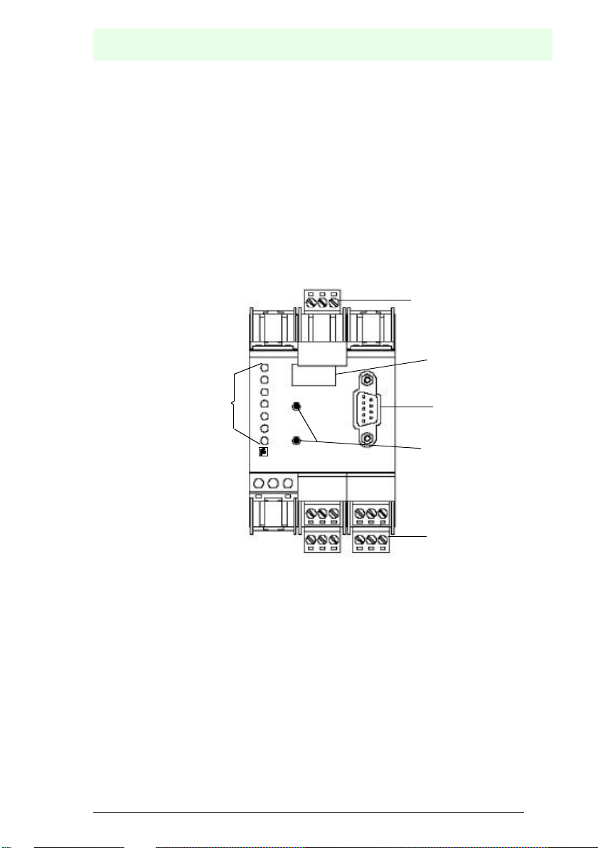
The following are found on the front of the AS-i/Profibus gateway (see diagram below):
1. Connection terminals for the AS-i circuit, also used for the power supply
2. A nine pin SUB-D connector as a Profibus-interface (see chapter 4.5),
3. 7 LEDs
4. A four position, seven section display for indicating the gateway's operating status
5. 2 buttons for projecting the gateway.
1
1 2 3
POWER
PB active
CONFIG ERR
3
U ASI
ASI active
PRG ENABLE
PRJ MODE
VAG-PB-KF-R4
192820
21
30 31 32
29
22 23 24 25
7
8
RS485
26
33 34 35 36
9
4
2
27
5
1
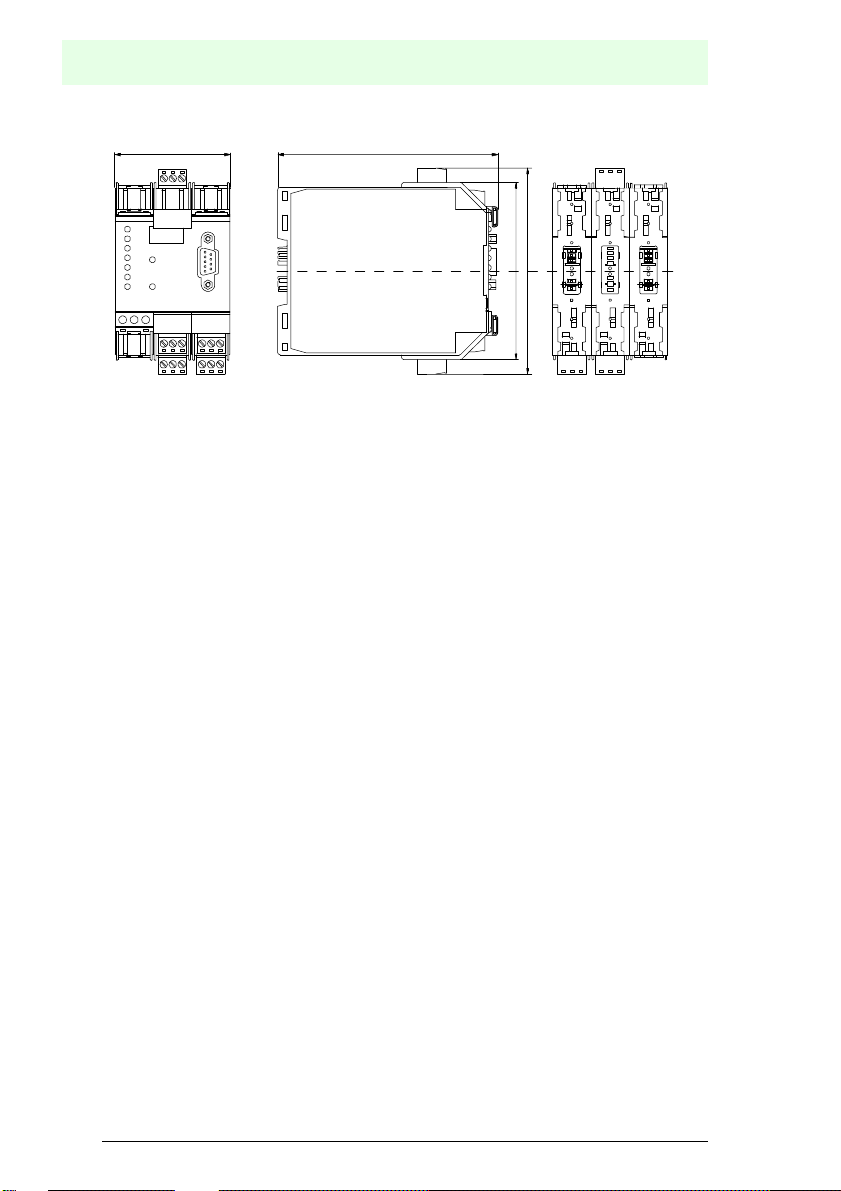
The following diagram provides the dimensions of the AS-i/PROFIBUS-gateway.
issue date 12.10.199 9
Subject to reasonable modifications due to technical advances. Copyright Pepperl+Fuchs, Printed in Germany
Pepperl+Fuchs Group · Tel.: Germany (621) 776-0 · USA (330) 4253555 · Singapore 7799091 · Internet http://www.pepperl-fuchs.com
13
Page 14
AS-Interface
Connections, Displays and Controls
60
115
107
92,5
5.2 Displays and Controls
The seven LEDs on the front of the gateway signal the following:
power The gateway is sufficiently supplied with power.
PB active LED on: The PROFIBUS communications are active.
LED off:PROFIBUS communications are inactive.
config err A configuration error is imminent or no PROFIBUS communications
are taking place (when the "PB active" LED is not illuminated). This
means that with configuration errors, at least one projected slave is
missing or the actual configuration data does not correspond with the
reference configuration data for a projected and recognized slave.
U AS-i The AS-i line is sufficiently supplied with power.
(AS-i Flag "APO").
AS-i active Standard operation is active (AS-i Flag "Normalbetrieb").
prg enable Automatic address programming is possible
(AS-i Flag "Auto_prog_available").
Precisely one slave is missing in the protected operating mode. This
slave can be replaced with a slave of similar design and an address
of 0. The gateway automatically programs the new slave to the faulty
address and thereby resolves the configuration error.
prj mode The gateway is in the projection mode
(AS-i Flag "projecting_active").
Subject to reasonable modifications due to technical advances. Copyright Pepperl+Fuchs, Printed in Germany
Pepperl+Fuchs Group · Tel.: Germany (621) 776-0 · USA (330) 4253555 · Singapore 7799091 · Internet http://www.pepperl-fuchs.com
14
issue date 12.10.199 9
Page 15

AS-i/PROFIBUS Gateway
Connections, Displays and Controls
The two buttons have the following functions:
mode Used to switch between the projection mode and the protected oper-
ating mode and to store the actual AS-i configuration as the reference
configuration.
set Selection and storage of an AS-i slave address.
5.3 Mounting and Connections
5.3.1 Mounting
The KF… design of the gateway can be mounted on a 35 mm DIN rail in accordance
with EN 50022 and facilitates electrical connection through the "Power Rail". It is also
possible to use the more conventional and expensive method of cable connections to
terminals with this design.
The gateway is snapped directly onto the DIN rail. When using the power rail, an electrical connection is automatically made (to the AS-i Bus) by snapping the gateway
onto the rail leads..
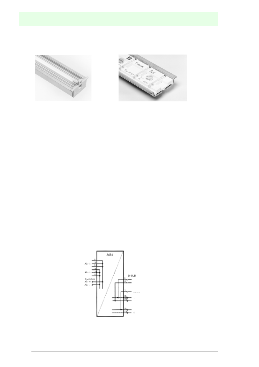
5.3.2 Connection via the Power Rail
The PR05 power rail is an insert for the DIN rail in accordance with EN 50 022. The
UPR 05 is delivered with the appropriate DIN rail.
The 5 pin version of the power rail must be used during the establishment of AS-interface circuits. Two of the five power rails make up the AS-i bus.
issue date 12.10.199 9
Subject to reasonable modifications due to technical advances. Copyright Pepperl+Fuchs, Printed in Germany
Pepperl+Fuchs Group · Tel.: Germany (621) 776-0 · USA (330) 4253555 · Singapore 7799091 · Internet http://www.pepperl-fuchs.com
15
Page 16
AS-Interface
Connections, Displays and Controls
Lead breakage as well as a short circuit caused by the power rail is prevented due to
the power rail's solid construction..
UPR 05
PR 05
5.3.3 Device Terminal Connections
In addition to or in combination with power rail connections, the KF… designs can be
conventionally connected by means of removable device terminals. The terminal arrangement is shown below.
The device terminals consist of screw type cable piercing terminals which allow for
the connection of 14 AWG cables (2.5 mm²). The connectors are 3 pin connectors;
they can be keyed to prevent connection errors.
Removable terminals simplify the assembly of the switch encloser and allow for the
replacement of components without taking the system off line.
5.3.4 Gateway Power Supply
The gateway is supplied through the AS-i circuit. A connection to the AS-i cable is established by means of the power rail and/or with the device terminals. The terminal
layout is displayed in the diagram above.
It is important to note when using the power unit that these AS-Interfaces are compatible and have the necessary decoupling coils.
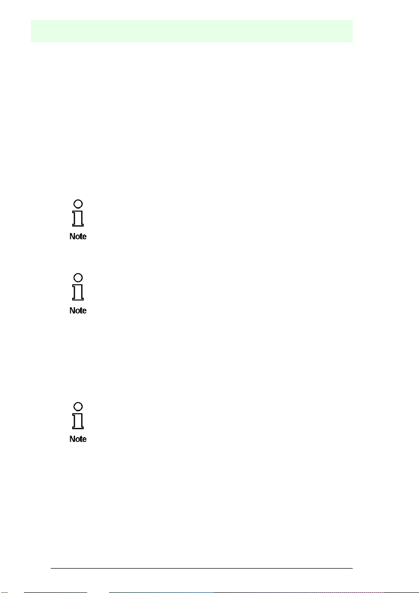
5.4 The PROFIBUS Interface
The serial interface is a 9 pin SUB-D connector. It is located on the right side of the
device front. The other possibility is to use the device terminals. The wiring is shown
in the picture below:
RxD/TxD-P
RxD/TxD-N
Shield
PROFIBUS
RxD/TxD-P
interface
RxD/TxD-N
Shield
The AS-i/Profibus-Gateway with an RS485 interface transmitts and receives through
pins 3 and 8 of the SUB-D connector or terminals 25 and 26 of the device terminals.
The RxD-TxD-P signal (B cable per PROFIBUS specifications) is assigned to pin 3
Subject to reasonable modifications due to technical advances. Copyright Pepperl+Fuchs, Printed in Germany
Pepperl+Fuchs Group · Tel.: Germany (621) 776-0 · USA (330) 4253555 · Singapore 7799091 · Internet http://www.pepperl-fuchs.com
16
issue date 12.10.199 9
Page 17

AS-i/PROFIBUS Gateway
Connections, Displays and Controls
and to terminal 25. The RxD/TxD-N signal (A cable per PROFIBUS specifications) is
assigned to pin 8 and to terminal 26.
In order to prevent equalizing currents, the interface cable's shielding is connected
with the gateways grounding clamp through a capacitor. Otherwise, it should be galvanically grounded.
issue date 12.10.199 9
Subject to reasonable modifications due to technical advances. Copyright Pepperl+Fuchs, Printed in Germany
Pepperl+Fuchs Group · Tel.: Germany (621) 776-0 · USA (330) 4253555 · Singapore 7799091 · Internet http://www.pepperl-fuchs.com
17
Page 18

AS-Interface
Connections, Displays and Controls
Subject to reasonable modifications due to technical advances. Copyright Pepperl+Fuchs, Printed in Germany
Pepperl+Fuchs Group · Tel.: Germany (621) 776-0 · USA (330) 4253555 · Singapore 7799091 · Internet http://www.pepperl-fuchs.com
18
issue date 12.10.199 9
Page 19
AS-i/PROFIBUS Gateway
Operating the AS-i/PROFIBUS Gateway
6 Operating the AS-i/PROFIBUS Gateway
6.1 Master Start-Up
After powering on, all segments of the figure display and all LEDs light up for approximately one second (self-test). Afterwards, the LEDs display the condition of their respective flags. The LCD displays the condition of the master:
40 Off-line Phase
The AS-i Master initializes—there is no data communication on the AS-i.
If the AS-i circuit is insufficiently powered (“U ASI” does
not light up) or there is no communication relationship
between the Profibus master and the AS-i/PROFIBUS
Gateway, the master remains in the off-line phase.
In configuration mode or when an AS-i Control program is started automatically the device can leave the Off-line phase.
In protected mode, if the Profibus communication is interrupted, the AS-i
Master switches to the off-line phase after the watchdog time of the Profibus has expired unless an AS-i Control program is running and was
started automatically.
41 Detection Phase
Start of the start-up phase, where the system looks for slaves located on
the AS-i. The master remains in the detection phase until it finds at least
one slave.
42 Activation Phase
Condition at the end of the start-up operation where the parameters are
transmitted to all connected and recognized slaves. This enables access
to the AS-i slaves’ data connections.
431Start of Normal Operation
In normal operation the AS-i master can exchange data with all active
slaves. It transmits management messages and looks for and activates
newly connected slaves. During normal operation, the system keeps the
maximum cycle time of 5 milliseconds.
6.2 Configuration Mode
The configuration mode serves to configure the AS-i circuit.
In the configuration mode, all recognized slaves are activated even
when the desired and actual configurations do not match.
1. Activation phase and the start of normal operation maybe so short that the numbers can not be seen in the display.
issue date 12.10.199 9
Subject to reasonable modifications due to technical advances. Copyright Pepperl+Fuchs, Printed in Germany
Pepperl+Fuchs Group · Tel.: Germany (621) 776-0 · USA (330) 4253555 · Singapore 7799091 · Internet http://www.pepperl-fuchs.com
19
Page 20
AS-Interface
Operating the AS-i/PROFIBUS Gateway
Pressing the “mode” button for at least five seconds switches the master to configuration mode. While in configuration mode, the yellow “prj mode” LED lights up.
The system then displays one after the other all detected slaves at a speed of two per
second. If the display is empty, no slaves were detached on the AS-i circuit.
In configuration mode, all recognized slaves are activated except of slave zero. The
AS-i Master is in normal operation. There is data exchange between the AS-i Master
and all AS-i slaves detected by the master regardless of whether the detected AS-i
slaves were projected before.
When delivered the AS-i/PROFIBUS Gateway is in configuration mode.
6.3 Protected Operating Mode
In contrast with the configuration mode in the protected mode there is
only data exchange between the AS-i Master and the projected AS-i
slaves.
6.3.1 Switching to Protected Operating Mode
You leave the configuration mode by pressing the “mode” button.
Pressing the button shortly:
Exits the configuration mode without projecting the current AS-i configuration.
Pressing the button for more than five seconds:
Exits the configuration mode and projects the actual AS-i configuration. Simultaneously the actual AS-i configuration is stored as nominal configuration
in the EEPROM.
If the system detects an AS-i slave with address zero on the AS-i, it can
not leave the configuration mode.
In the protected operating mode, only AS-i slaves that are projected and whose actual
configurations match the nominal configurations will be activated.
6.3.2 Configuration Errors in Protected Operating Mode
As long as there is no configuration error, the numeric display is turned off while in
protected operating mode. Otherwise, the that address a faulty assignment is displayed. A faulty assignment occurs when a slave has been recognized or projected
but cannot be activated.
Subject to reasonable modifications due to technical advances. Copyright Pepperl+Fuchs, Printed in Germany
Pepperl+Fuchs Group · Tel.: Germany (621) 776-0 · USA (330) 4253555 · Singapore 7799091 · Internet http://www.pepperl-fuchs.com
20
issue date 12.10.199 9
Page 21

AS-i/PROFIBUS Gateway
Operating the AS-i/PROFIBUS Gateway
If there are more than one faulty assignments the one that was first detected is displayed. Pressing the “set” button shortly displays the next higher faulty address.
Shortly appearing configuration errors are stored in the device (advanced AS-i diagnosis). The last error that occurred can be displayed by pressing the set button. If a
short AS-i power failure is responsible for the configuration error the display shows a
“39“.
6.4 Assigning an AS-i Address in Configuration Mode
AS-i can be put into operation in a very comfortable manner by using the Windows
software AS-i Control Tools (see chapter 9.1)(addressing directly or with the AS-i address assistant).
Furthermore you can use a hand held addressing device.
If you don’t have neither a PC nor a hand held addressing device, address assigning
of the AS-i slaves is also possible with the AS-i/PROFIBUS Gateway using the push
buttons. How it works is described as follows.
6.4.1 Assigning a Slave Address
(assigning an available address to a slave with address zero)
In configuration mode, the addresses of all detected slaves are displayed one after
the other. To display the next higher available operating address, press the “set” button shortly. Each time you press the “set” button, the next available address is displayed.
Chose the displayed address as your target address by pressing the button for more
than five seconds. The address display blinks. The master is ready for programming;
pressing the “set” button again addresses the connected slave with address zero to
the target (blinking address.
Any errors will be displayed by their error codes according to chapter 10. Otherwise,
the detected slaves are displayed again as described in chapter 6.2.
6.4.2 Erasing the Slave Address
AS-iIn configuration mode, the addresses of all recognized slaves are displayed one
after the other. By pressing and releasing the “set” button, the master displays the
next available address. If you press the button for more than five seconds while the
address of a detected slave is displayed, this slave is will get the address zero and
the display shows “00”.
When you release the button, the display continues to display the detected slaves.
issue date 12.10.199 9
Subject to reasonable modifications due to technical advances. Copyright Pepperl+Fuchs, Printed in Germany
Pepperl+Fuchs Group · Tel.: Germany (621) 776-0 · USA (330) 4253555 · Singapore 7799091 · Internet http://www.pepperl-fuchs.com
21
Page 22

AS-Interface
Operating the AS-i/PROFIBUS Gateway
6.5 Programming the Address in Case of Configuration Errors
6.5.1 Automatic Address Assignment
One of AS-i’s great advantages is the automatic address assignment. If
a slave fails, it can be replaced by one of the same type with address
zero. The master will detect the replacement and automatically
addresses the new slave with the address of the faulty one.
For automatic programming to work, some requirements must be met:
1.The AS-i master must be in the protected operating mode.
2.The “Auto_Address_Assign” release flag must be set.
3.Only one of the projected slaves may not be detected.
If these requirements are met, the AS-i master’s “prg enable” LED lights up and a
slave with address zero will be automatically assigned to the operating address of the
missing slave.
If the two slaves have different configuration data, i.e. are not of the
same type as far as AS-i is concerned, the automatic address assignment will not be carried out.
6.5.2 Manual Address Assignment
If several slaves fail, they cannot be replaced automatically by the AS-i
master. You must set their addresses manually. If this should not be
done via the Profibus interface (using the AS-i Control Tools) or with a
hand held addressing device, you can set them with the push buttons
and the figure display of the device.
In protected operating mode, wrong assignments are displayed as errors (see chapter
6.3). By pressing the “set” button, you can display all faulty assignments one after the
other. By pressing the “set” button for more than five seconds, you can select the currently displayed address as a potential target address, and the display starts to blink.
If the faulty slave was previously replaced by a slave with address zero, the new slave
can now be programmed for the blinking address by pressing the “set” key again. As
a requirement, the new slave’s configuration data must match the configuration data
for the blinking address.
After the address has been successfully set, the next faulty assignment is displayed
and the address assignment can begin from the start. Otherwise, the system displays
an error code (chapter 10). When all faulty assignment are eliminated the display is
empty.
Subject to reasonable modifications due to technical advances. Copyright Pepperl+Fuchs, Printed in Germany
Pepperl+Fuchs Group · Tel.: Germany (621) 776-0 · USA (330) 4253555 · Singapore 7799091 · Internet http://www.pepperl-fuchs.com
22
issue date 12.10.199 9
Page 23

AS-i/PROFIBUS Gateway
Operating the AS-i/PROFIBUS Gateway
6.6 Setting of the Profibus Station Address and the Protocol Type
6.6.1 Profibus Station Address
The addressing of the AS-i/PROFIBUS Gateway as a Profibus slave
can be done locally at the gateway or via Profibus according to the
Profibus norm.
Station addresses from 1 to 99 can be set, when delivered station address 3 is set.
For the relocation, both the "set" button and the "mode" button have to be pushed si-
multaneously for at least 5 seconds until the current bus address is shown on the LCD
display. With every pushing of the "set" button, the station address can now be increased by 1.
Once the desired Profibus station address is shown on the display, it will be stored
non-volatile in the EEPROM by pushing the “mode“ button.
6.7 Error Messages
The system displays error codes for error messages that do not point to
faulty assignments on the AS-icircuit. The code numbers are larger than
50 and are therefore outside the slave address range. These codes are
described in the appendix, chapter 10.
issue date 12.10.199 9
Subject to reasonable modifications due to technical advances. Copyright Pepperl+Fuchs, Printed in Germany
Pepperl+Fuchs Group · Tel.: Germany (621) 776-0 · USA (330) 4253555 · Singapore 7799091 · Internet http://www.pepperl-fuchs.com
23
Page 24

AS-Interface
Operating the AS-i/PROFIBUS Gateway
Subject to reasonable modifications due to technical advances. Copyright Pepperl+Fuchs, Printed in Germany
Pepperl+Fuchs Group · Tel.: Germany (621) 776-0 · USA (330) 4253555 · Singapore 7799091 · Internet http://www.pepperl-fuchs.com
24
issue date 12.10.199 9
Page 25

AS-i/PROFIBUS Gateway
Advanced Diagnostics for AS-i Masters
7 Advanced Diagnostics for AS-i Masters
The advanced AS-i diagnostics serves to locate occasionally occurring errors and to
judge the quality of data transmission on AS-i without additional diagnostics tools.
The AS-i Control Tools, Bihl+Wiedemann’s software for the comfortable commissioning of the AS-Interface and the programming of AS-i Control, will include the operation
of the Advanced Diagnostics from version 3.0 on.
7.1 List of Corrupted AS-i Slaves (LCS)
To locate occasionally occurring short-time configuration errors the AS-i Masters with
advanced diagnostics manage beside the list of projected slaves (LPS), the list of detected slaves (LDS) and the list of activated slaves (LAS) a forth list, the list of cor-
rupted slaves (LCS). This list contains entries of all AS-i slaves which were
responsible for at least one configuration error since powering up the AS-i master or
reading the list. Short-time AS-i power failures are represented in the LCS at the position of AS-i slave with address 0.
With every read access the LCS will be deleted.
The last short-time configuration error can also be displayed on the AS-i
Master:
Pressing the “set“ button of the AS-i Master shows the AS-i slave which
was responsible for the last short-time configuration error. Was there a
short-time AS-i power failure the display shows “39“ after pressing the
“set“ button.
7.2 Error Counter: Counter of corrupted data telegrams
The AS-i Master with advanced diagnostics has an error counter for each AS-i slave,
which is increased every time there is a corrupted AS-i telegram. This makes it possible to judge the quality of the AS-i network, even if only a few corrupted telegrams
occurred and the AS-i slave did not cause any configuration errors.
The counter values can be read via the host interface and will be
deleted with every read access. The counter value is limited to 254. 255
means counter overflow.
The error counter is included in the command Master | AS-i Diagnostics of AS-i Control Tools version 3.0.
7.3 Off-line Phase on Configuration Errors
The AS-i Masters with advanced diagnostics offer the possibility to put themselves
into the Off-line Phase when a configuration error on the AS-Interface occurs. In this
issue date 12.10.199 9
Subject to reasonable modifications due to technical advances. Copyright Pepperl+Fuchs, Printed in Germany
Pepperl+Fuchs Group · Tel.: Germany (621) 776-0 · USA (330) 4253555 · Singapore 7799091 · Internet http://www.pepperl-fuchs.com
25
Page 26

AS-Interface
Advanced Diagnostics for AS-i Masters
way the security of the application can be ensured. The reaction to a configuration error is very fast and the host can be relieved from this task. If there are any problems
on the AS-i network, the AS-interface can be switched to a secure state.
There are two different ways to parameterize the AS-i Master for this feature:
• Every configuration error during normal operation in protected mode releases the
Off-line Phase.
• For each slave address can be chosen whether a configuration error on this ad-
dress will release the Off-line Phase or not. This information is stored in the List of
Off-line Slaves (LOS).
The user himself can decide how the system reacts to a configuration error on the
AS-interface. The AS-i Master can release the Off-line Phase in critical situations,
i.e. only with certain slave addresses, while in less critical situations (if one of the
other AS-i slaves have a configuration error) only the error message configuration
error is sent to the host, but AS-i is still running.
The parameterization of Off-line Phase on Configuration Error is also supported by
the AS-i Control Tools version 3.0.
Subject to reasonable modifications due to technical advances. Copyright Pepperl+Fuchs, Printed in Germany
Pepperl+Fuchs Group · Tel.: Germany (621) 776-0 · USA (330) 4253555 · Singapore 7799091 · Internet http://www.pepperl-fuchs.com
26
issue date 12.10.199 9
Page 27

AS-i/PROFIBUS Gateway
Profibus-DP
8 Profibus-DP
In this chapter, you learn everything necessary to run the AS-i/PROFIBUS Gateway
in a Profibus-DP network.
For data exchange on Profibus-DP there are three operation modes: the easy mode,
the advanced mode and the professional mode (advanced mode with management
channel).
Hint: If you try to put an AS-i/PROFIBUS Gateway in operation the first
time it is advisable to use the easy mode because it is much easier than
the advanced modes.
The following table shows the differences between the three modes:
following Functions are available
Transmission of AS-i input and
outut data
AS-i circuit can be configured
locally on the gateway
Putting into Operation without additional parameterization of the Profibus master
Working with a standard I/O-configuration on Profibus-DP
Detection of AS-i errors via DPdiagnosis
Transmission of AS-i parameters to
the gateway while the system is
running (e.g. switching of the measurement range of sensors)
Configuring and parameterizing the
AS-i circuit by the DP-master
Reading and Writing AS-i Control
programs via Profibus-DP
AS-i Transmission of user flags for
the AS-i Control program via Profibus DP
Adjust the size of the I/O windows
to the actual extension of the AS-i
circuit
Transmission of additional AS-i
commands and advanced diagnosis
in easy mode in advanced
mode
X X X
X - X
X - -
X - -
X X X
- X X
- X X
- X -
- X X
- X X
- X X
in professional
mode
issue date 12.10.199 9
Subject to reasonable modifications due to technical advances. Copyright Pepperl+Fuchs, Printed in Germany
Pepperl+Fuchs Group · Tel.: Germany (621) 776-0 · USA (330) 4253555 · Singapore 7799091 · Internet http://www.pepperl-fuchs.com
27
Page 28

AS-Interface
Profibus-DP
8.1 Easy Mode
8.1.1 Mapping of the AS-i data in the Profibus-DP-Telegram
The inputs and outputs of the AS-i network are mapped identically in the DP master's
input or output memory area respectively. In the easy mode the DP-telegram contains
16 bytes in- and output data with a single master.
AS-i circuit 1:
Byte 0 Byte 1 ... Byte 15
Slave 1, AS-i flags Slave 3, Slave 2 ... Slave 31, Slave 30
The AS-i flags and every AS-i slave take up four bits. The meaning and allocation of
these bits is explained in the appendix, chapter 11.3.1.
If the AS-i flags shall not be used, you have to make sure that by all
means these four bits are set to zero.
8.1.2 Configuration of the AS-i Network
The AS-i network can be put into operation without the Profibus-DP master. A connection to the Profibus-DP master is not necessary.
A comfortable way to configure the AS-i circuit on the AS-i/PROFIBUS Gateway is to
use the Windows software AS-i Control Tools.
However it is also possible to configure the AS-i network locally on the gateway by
using the push buttons “set“ and “mode“ (see chapter 6.4)
8.1.3 Projecting of the Profibus-DP Master
To project the Profibus-DP network you have to copy a GSD-file (enclosed on diskette) to the working directory of your Profibus configuration software (some programs have a directory named GSD, where the GSD-files have to be copied to,
please see the manual of the used software). Depending on the software you may
have to dispatch a command like „read GSD-files“.
The GSD-files can be found on the enclosed diskette „AS-i/PROFIBUS-Gateway IBM
PC Software“ in the directory GSD.
For the easy mode the following GSD-files are available:
bwes1742.gsd
device: AS-i/PROFIBUS-DP Gateway,
model name in the GSD-file: „AS-i/DP“
If the Profibus configuration software needs the older type files instead of the GSDfiles, please read the file \gsd\readme.txt on the enclosed diskette.
8.1.4 Parameterization of the Profibus-DP Slave
The parameters the gateway needs are completely appropriated by the GSD-file,
there is no need to state user-parameters. If nevertheless user-parameters are transmitted, the device will switch to easy mode, if the first byte (element selection) is
00
.
hex
Subject to reasonable modifications due to technical advances. Copyright Pepperl+Fuchs, Printed in Germany
Pepperl+Fuchs Group · Tel.: Germany (621) 776-0 · USA (330) 4253555 · Singapore 7799091 · Internet http://www.pepperl-fuchs.com
28
issue date 12.10.199 9
Page 29

AS-i/PROFIBUS Gateway
Profibus-DP
8.1.5 Configuration of the Profibus-DP Slave
In the easy mode the gateway uses a fixed I/O-configuration. If you use the GSD-file
select the module “Standardmodus“.
If you configure the master without the GSD-file, select the identification byte
3F
(=63
hex
For double masters you need this identification byte for each AS-i circuit.
8.2 Advanced Mode
The extended functionality of the advanced mode affords a more extensive configuration of Profibus-DP. The I/O window can be adjusted optimally to the additional
transmitted data (AS-i parameters, user memory, AS-i Control Code). The length of
the I/O-window depends on the following factors:
• number of the AS-i slaves (number of input and output bytes)
• shall AS-i parameters be transmitted?
• shall AS-i Control code be transmitted?
• shall user memory be transmitted?
Size of the Window for the AS-i Input and Output Data
The size of the window for the AS-i input and output data is automatically adjusted to
the AS-i configuration that is transmitted in the Profibus parameter telegram (user-parameter).
However, you must pay attention to this when configuring the Profibus-DP slave (see
chapter 8.2.3).
Transmission of AS-i Parameters
For the transmission of AS-i parameters the DP-input and output data fields are enlarged by two bytes each. The AS-i slave address and the AS-i parameters are entered to these bytes. In the output data field, the DP master deposits the AS-i
parameters to be written; in the input data field, the gateway deposits the data read
during the AS-i parameterization.
The AS-i slaves are parameterized sequentially, i. e. only one slave can be parameterized in one Profibus cycle. The gateway signals errors of the parameterization by
setting the leftmost bit in the slave address.
Transmission of AS-i Control code
).
dec
For AS-i/PROFIBUS Gateways with 2 AS-i Masters and/or the advanced AS-i diagnostics1 we recommend to use the professional
mode instead of the older advanced mode.
1. these are all devices that were delivered since September 1998; these devices have the following feature string:
„*B..Dc..***.....“ oder „*B..Dc2.***.....“, * is a placeholder for various characters
(this string can be read with AS-i Control Tools with the command Master | Identity)
issue date 12.10.199 9
Subject to reasonable modifications due to technical advances. Copyright Pepperl+Fuchs, Printed in Germany
Pepperl+Fuchs Group · Tel.: Germany (621) 776-0 · USA (330) 4253555 · Singapore 7799091 · Internet http://www.pepperl-fuchs.com
29
Page 30

AS-Interface
Profibus-DP
For the programming of AS-i Control, the I/O field is further enlarged by 5-17 additional bytes. They contain an identification byte (read/write/start/stop), the base address
and 2-14 bytes user data. It is not possible to read and write at the same time.
Transmission of user memory
User memory can be transmitted in the I/O field by adding bytes for the memory locations to be written (O-field) or to be read (I-field). The amount of user memory to be
written or read can be different.
8.2.1 Mapping of the AS-i Data in the Profibus-DP Telegram
The data in the DP telegram is always mapped in the same fixed order:
• AS-i I/O data
• AS-i parameters
• AS-i Control code
• user memory
If some elements are missing (e.g. no transfer of the AS-i Control code), subsequent
elements are added directly.
The individual parts of the DP-telegram are coded as follows:
N bytes
AS-i I/O data
2 bytes
AS-i parameter
5-17 bytes
AS-i Control
M bytes
user memory
code
user memory 0..
user memory M-1
high address, control byte
low-address, L bytes data
AS-i slave address, AS-i parameter
byte 0. .. byte N-1
slave 1 AS-i flags ... slave (K-1) slave (K-2)
with K = number of AS-i slaves + 1
(instead of slave 0 the AS-i flags are transmitted)
N = K/2
M = number of user memory bytes up to 128 bytes
L = number of bytes of AS-i Control code
(calculated out of value in element selection of the user-parameter telegram)
Subject to reasonable modifications due to technical advances. Copyright Pepperl+Fuchs, Printed in Germany
Pepperl+Fuchs Group · Tel.: Germany (621) 776-0 · USA (330) 4253555 · Singapore 7799091 · Internet http://www.pepperl-fuchs.com
30
issue date 12.10.199 9
Page 31

AS-i/PROFIBUS Gateway
Profibus-DP
The AS-i flags and every AS-i slave take up four bits. The meaning and allocation of
these bits is explained in the appendix, chapter 11.3.2.
If the AS-i flags shall not be used, you have to make sure that by all
means these four bits are set to zero.
Bit allocation AS-i parameters: see appendix, chapter 11.3.2.
Constants for the control byte in the DP-telegram's AS-i Control part: see appendix,
see chapter 11.3.3.
8.2.2 Configuration of the AS-i Network
During the building up of the connection to a Profibus-DP master, the AS-i network is
configured via the Profibus. The AS-i configuration does not have to be stored locally
(via the push buttons mode and set or the AS-i Control Tools). Merely the AS-i slaves
have to get the designated addresses.
The AS-i/PROFIBUS Gateway compares the nominated AS-i configuration received
from the DP-master with the actual configuration of the AS-i network. If they match,
the gateway does data exchange on AS-i. (This does not affect the data exchange on
Profibus).
The AS-i configuration data of the AS-i slaves (ID-code and I/O-configuration) should
be known before configuring the DP-master. You find them in the AS-i slave's documentation.
The configuration via Profibus-DP offers the following advantage: The
AS-i configuration data of the AS-i network is stored in the DP-master.
This way, an immediate start-up without any need for manual intervention is possible when exchanging the gateway (one exception is the
Profibus station address).
8.2.3 Configuration of the Profibus-DP Master
To project the Profibus-DP network you have to copy a GSD-file (enclosed on diskette) to the working directory of your Profibus configuration software (some programs have a directory named GSD, where the GSD-files have to be copied to,
please see the manual of the used software). Depending on the software you may
have to dispatch a command like „read GSD-files“.
The GSD-files can be found on the enclosed diskette „AS-i/PROFIBUS-Gateway IBM
PC Software“ in the directory \GSD.
For the advanced mode the following GSD-files are available:
bwas1742.gsd
device: AS-i/PROFIBUS-DP Gateway,
model name in the GSD-file: „AS-i/DP-A“
If the Profibus configuration software needs the older type files instead of the GSDfiles, please read the file \gsd\readme.txt on the enclosed diskette.
issue date 12.10.199 9
Subject to reasonable modifications due to technical advances. Copyright Pepperl+Fuchs, Printed in Germany
Pepperl+Fuchs Group · Tel.: Germany (621) 776-0 · USA (330) 4253555 · Singapore 7799091 · Internet http://www.pepperl-fuchs.com
31
Page 32

AS-Interface
Profibus-DP
Parameterization of the Profibus-DP-Slave
The parameters needed by the gateway are coded in the user-parameters. They contain one byte element selection, the AS-i configuration data and AS-i parameters for
all the AS-i slaves and the statements about user memory bytes to be read and to be
written.
Element
selection
AS-i configuration data and
AS-i (startup-) parameters
user memory
statement
The fields are constructed as follows:
• Element selection (1 byte)
Bit field for the selection of the data to be transmitted:
Bit 0 = 1 Transmission of AS-i parameters
= 0 No transmission of AS-i parameters
Bit 1 = 1 Transmission of user memory
= 0 No transmission of user memory
Bit 2 = 1 Transmission of 2 bytes of AS-i Control code additionally
Bit 3 = 1 Transmission of 4 bytes of AS-i Control code additionally
Bit 4 = 1 Transmission of 8 bytes of AS-i Control code additionally
Bit 5 = 0 (reserved, 0 cogently necessary)
Bit 6 = 1 Transmission of AS-i input data
= 0 AS-i input data field is left out
Bit 7 = 1 Transmission of AS-i output data
= 0 AS-i output data field is left out
If the ID-Byte is set to 00hex, the device will switch to the easy mode.
• AS-i configuration data and AS-i (startup) parameters (62 bytes)
For each AS-i slave 2 bytes are used. AS-i slave 0 is disregarded.
In the first byte, the AS-i configuration data is specified. The AS-i ID-code is coded in the byte's high nibble and the I/O-configuration in its low nibble.
bit 7 bit 6 bit 5 bit 4 bit 3 bit 2 bit 1 bit 0
ID-code IO-configuration
In the second byte's low nibble, the AS-i (startup) parameters are transmitted.
The upper half of this byte is unused.
bit 7 bit 6 bit 5 bit 4 bit 3 bit 2 bit 1 bit 0
0 0 0 0 P3 P2 P1 P0
unused (=0) AS-i parameter
The default parameter for an AS-i slave is F
0F
is stated.
hex
Subject to reasonable modifications due to technical advances. Copyright Pepperl+Fuchs, Printed in Germany
Pepperl+Fuchs Group · Tel.: Germany (621) 776-0 · USA (330) 4253555 · Singapore 7799091 · Internet http://www.pepperl-fuchs.com
32
, so that normally as second byte
hex
issue date 12.10.199 9
Page 33

AS-i/PROFIBUS Gateway
Profibus-DP
If a slave address is to remain unused, either FF
hex
, FF
hex
or 256
dec
, 256
to be entered.
The highest slave address used determines the size of the
window for input and output data in the DP-data telegram.
The configuration of the DP-slave has to be adjusted accordingly (see below).
• user memory statement (4 bytes)
The user memory statement always has to be stated.
Byte 0:Start address of the user memory window in the input data telegram
(read user memory)
Byte 1:Length of the user memory window in the input data telegram
Byte 2:Start address of the user memory window in the output data telegram
(write user memory)
Byte 3:Length of the user memory window in the output data telegram
If user memory bytes shall only to be read or written, the appurtenant length byte
has to be set to 0.
If no user memory bytes shall be transmitted it is recommended to set the user
memory statement to FF
hex
FF
hex
FF
hex
FF
hex
.
The maximum length of the user memory window is 128 bytes.
Example: Parameter telegram for the advanced mode:
3 AS-i slaves and transmission of user memory, all slaves AS-i ID 0
Slave 1: 4 inputs
Slave 2: 4 outputs
Slave 3: 2 inputs, 2 outputs
from user memory byte 0 read 4 bytes of user memory
no writing of user memory
dec
has
El. slave 1 slave 2 slave 3 slave 4 slave 31 user mem. st.
conf
ID,IO
par conf
ID,IO
par conf
ID,IO
par conf
ID,IO
par conf
ID,IO
par
C2 00 0F 08 0F 03 0F FF FF ... FF FF 00 04 00 00
(all data stated in hexadecimal code)
Configuration of the Profibus-DP slave
In contrast to the easy mode, the size of the I/O window can be matched to the extension of the AS-i network. Its size in bytes amounts:
(highest AS-i slave address + 1) / 2
Any non-integer value has to be rounded up to a full byte. Extra bytes have to be added for possible AS-i (startup) parameters, user memory or AS-i Control code.
issue date 12.10.199 9
Subject to reasonable modifications due to technical advances. Copyright Pepperl+Fuchs, Printed in Germany
Pepperl+Fuchs Group · Tel.: Germany (621) 776-0 · USA (330) 4253555 · Singapore 7799091 · Internet http://www.pepperl-fuchs.com
33
Page 34

AS-Interface
Profibus-DP
Only "standard identification bytes" with a maximum size of 16 bytes or words may be
used as identification bytes. If the data windows to be transmitted shall be bigger than
16 bytes or words, they have to be out together out of several "standard identification
bytes".
If the requested data field length is smaller than the one calculated out of the parameter telegram, the gateway will not take up any communication relationship with the
DP-master.
The maximum data field length for input respectively output data is 149 bytes with a
device with one AS-i Master and 160 bytes with a device with two AS-i Masters.
8.3 Professional Mode
All AS-i/PROFIBUS Gateways with 2 AS-i Masters and/or the advanced AS-i diagnostics1 have a third operation mode, which we call the professional mode. We recommend the use of the professional mode instead of the older advanced mode.
The AS-i/PROFIBUS Gateways with 2 AS-i Masters only allow the use of the easy
mode or the professional mode. The AS-i/PROFIBUS Gateways (FMS/DP) only run
in the easy mode or the advanced mode.
The extended functionality of the advanced mode affords a more extensive configuration of Profibus-DP. The I/O-window has to be enlarged for the additional data
(management commands and user memory). The length of the I/O-window depends
on the following factors:
• number of the AS-i slaves (number of input and output bytes)
• size of the management channel (0, 3 or 5 Bytes)
• number of the user memory bytes
Size of the Window for the AS-i Input and Output Data
The size of the window for the AS-i input and output data has to be adjusted to the
AS-i configuration (see chapter 8.3.3).
Transmission of Management Commands (0, 3 or 5 bytes)
With the management commands you can transmit acyclically additional AS-i data
like e.g. AS-i parameters or reading the LDS or also writing the AS-i Control flags e.g.
to start an AS-i Control program.
The management channel uses either 3 or 5 bytes. If the commands write LPS, read
LPS, read LAS, read LDS, read LCS, read communication errors, write LOS or read
LOS shall be used, the management channel has to have a length of 5 bytes because
these commands use 4 bytes of data.
The management channel is built up as follows:
byte 0 byte 1 - 2 respectively 1 - 4
Profibus output data command byte output data
Profibus input data mirrored command byte input data
1. these are all devices that were delivered since September 1998; these devices have the following feature string:
„*B..Dc..***.....“ oder „*B..Dc2.***.....“, * is a placeholder for various characters
(this string can be read with AS-i Control Tools with the command Master | Identity)
Subject to reasonable modifications due to technical advances. Copyright Pepperl+Fuchs, Printed in Germany
Pepperl+Fuchs Group · Tel.: Germany (621) 776-0 · USA (330) 4253555 · Singapore 7799091 · Internet http://www.pepperl-fuchs.com
34
issue date 12.10.199 9
Page 35

AS-i/PROFIBUS Gateway
Profibus-DP
If the same command byte shall be sent several times one after the other, the bit 7
(valence 27) has to be toggled each repetition.
The bit 6 (valence 26) of the command byte states the number of the AS-i Masters to
address to. If this bit is 0, AS-i Master 1 is addressed, otherwise AS-i Master 2. With
single masters this bit has to be 0, with double masters the AS-i circuit to address can
be selected. (e.g. command read AS-i Control Flags of AS-i circuit 2: 4D
After execution of the command the command byte is mirrored. Illegal commands
(AS-i circuit number 2 with single masters, illegal command byte or a data field which
is too short) always return as mirrored command byte 00
was set.
Commands that may fail return an error code (00
hex
hex
: OK, FF
or 80
hex
: error) in data byte[0]
hex
(status).
The possible commands are listed as follows:
)
hex
, if the toggle bit
AS-i function command
Idle
(no function)
write projected
parameter
read projected
parameter
output 00
input 00
output 01
input 01
output 02
input 02
write parameter output 03
input 03
read actual
paramter
write (project)
actual parameter
write projected
coniguration
read projected
coniguration
write projected
coniguration
read actual configuation
output 04
input 04
output 05
input 05
output 06
input 06
output 07
input 07
output 08
input 08
output 09
input 09
address AS-i slave output 0A
input 0A
byte
hex
hex
hex
hex
hex
hex
hex
hex
hex
hex
hex
hex
hex
hex
hex
hex
hex
hex
hex
hex
hex
hex
data
byte[0]
data
byte[1]
data
byte[2]
data
byte[3]
- - - -
- - - -
slave address parameter - -
status - - -
slave address - - -
status parameter - -
slave address parameter - -
status parameter - -
slave address - - -
status parameter - -
- - - -
status - - -
slave address conf.-daten - -
status - - -
slave address - - -
status conf.-daten - -
- - - -
status - - -
slave address - - -
status conf.-daten - -
old address new address - -
status - - -
issue date 12.10.199 9
Subject to reasonable modifications due to technical advances. Copyright Pepperl+Fuchs, Printed in Germany
Pepperl+Fuchs Group · Tel.: Germany (621) 776-0 · USA (330) 4253555 · Singapore 7799091 · Internet http://www.pepperl-fuchs.com
35
Page 36

AS-Interface
Profibus-DP
AS-i function command
AS-i command call output 0B
input 0B
write AS-i Control
flags
read AS-i Control
flags
output 0C
input 0C
output 0D
input 0D
write LPS output 0E
input 0E
read LPS output 0F
input 0F
read LAS output 10
input 10
read LDS output 11
input 11
read LCS output 12
input 12
read communication error
output 13
input 13
write LOS output 14
input 14
read LOS output 15
input 15
remarks to the table:
• possible values for status:
The status byte, which is returned from certain commands, can have the follow-
ing values:
FF error occurred at execution of the host command
00 no error occurred
If errors occur while changing slave addresses, the status byte contains one of
the following error codes:
01 no failure.
02 the slave, whose address should be changed does not exist.
03 There is a slave with address zero.
byte
hex
hex
hex
hex
hex
hex
hex
hex
hex
hex
hex
hex
hex
hex
hex
hex
hex
hex
hex
hex
hex
hex
data
byte[0]
data
byte[1]
data
byte[2]
data
byte[3]
slave address data - -
status answer - -
flags - - flags - - -
- - - -
flags - - -
LPS LPS LPS LPS
status - - -
- - - -
LPS LPS LPS LPS
- - - -
LAS LAS LAS LAS
- - - LDS LDS LDS LDS
LCS LCS LCS LCS
- - -
index (0-7) - - -
error error error error
LOS LOS LOS LOS
- - - -
- - - -
LOS LOS LOS LOS
Subject to reasonable modifications due to technical advances. Copyright Pepperl+Fuchs, Printed in Germany
Pepperl+Fuchs Group · Tel.: Germany (621) 776-0 · USA (330) 4253555 · Singapore 7799091 · Internet http://www.pepperl-fuchs.com
36
issue date 12.10.199 9
Page 37

AS-i/PROFIBUS Gateway
Profibus-DP
04 The address to which the slave shall be addressed
is reserved by another slave
05 The slave could not be addressed to address 0.
06 The new operation address could not be assigned.
07 The new operation address could not be stored
in the EEPROM of the slave.
• AS-i command call :
The function of the execution control Execute_Command() is executed. The in-
formation part of the master request has to be stated in “data“. (see AS-i specification).
The AS-i Master stores the slave answer in the byte “answer“.
• LPS, LAS, LDS, LCS, LOS:
Structure of the AS-i slave lists see appendix, chapter 11.1.
• read communication errors:
For each slave there is one byte for the number of communication errors that
occurred since the last read access. With every read access only 4 bytes are
read simultaneously. Therefore you have to state the index for the data you
want to read:
index = slave address / 4 (integer)
data byte number = slave address - (4 * index)
Transmission of user memory
The user memory is transmitted in an own Profibus slot. The amount of user memory
to be written or read can be different.
8.3.1 Mapping of the AS-i Data in the Profibus-DP Telegram
The data in the DP telegram is always mapped in the same fixed order:
• AS-i I/O data
• AS-i parameters
• AS-i Control code
• user memory
If some elements are missing (e.g. no transfer of the AS-i Control code), subsequent
elements are added directly.
The AS-i data is represented in the DP-telegram as follows:
byte 0 byte 1 ... byte N-1
slave 1, AS-i flags slave 2, slave 3 ... slave(K-1), slave(K-2)
with K = number of AS-i slaves + 1
(instead of slave 0 the AS-i flags are transmitted)
N = K/2
issue date 12.10.199 9
Subject to reasonable modifications due to technical advances. Copyright Pepperl+Fuchs, Printed in Germany
Pepperl+Fuchs Group · Tel.: Germany (621) 776-0 · USA (330) 4253555 · Singapore 7799091 · Internet http://www.pepperl-fuchs.com
37
Page 38

AS-Interface
Profibus-DP
The AS-i flags and every AS-i slave take up four bits. The meaning and allocation of
these bits is explained in the appendix, chapter 11.3.1.
If the AS-i flags shall not be used, you have to make sure that by all
means these four bits are set to zero.
8.3.2 Configuration of the AS-i Network
During the building up of the connection to a Profibus-DP master, the AS-i network is
configured via the Profibus, unless the AS-i configuration and the AS-i (startup) parameters are not stated in the Profibus parameter telegram. The AS-i configuration
only has to be stored locally (via the push buttons mode and set or the AS-i Control
Tools), if the configuration of AS-i was not stated in the Profibus parameter telegram.
Merely the AS-i slaves have to get the designated addresses.
The AS-i/PROFIBUS Gateway compares the nominated AS-i configuration received
from the DP-master with the actual configuration of the AS-i network. If they match,
the gateway does data exchange on AS-i. (This does not affect the data exchange on
Profibus).
The AS-i configuration data of the AS-i slaves (ID-code and I/O-configuration) should
be known before configuring the DP-master. You find them in the AS-i slave's documentation.
The configuration via Profibus-DP offers the following advantage: The
AS-i configuration data of the AS-i network is stored in the DP-master.
This way, an immediate start-up without any need for manual intervention is possible when exchanging the gateway (one exception is the
Profibus station address).
If the AS-i configuration and the AS-i (startup) parameters were not stated in the Profibus parameter telegram AS-i has to be projected (and the configuration stored) with
the push buttons at the device or with the windows software AS-i Control Tools.
8.3.3 Configuration of the Profibus-DP Master
To project the Profibus-DP network you have to copy a GSD-file (enclosed on diskette) to the working directory of your Profibus configuration software (some programs have a directory named GSD, where the GSD-files have to be copied to,
please see the manual of the used software). Depending on the software you may
have to dispatch a command like “read GSD-files“.
The GSD-files can be found on the enclosed diskette „AS-i/PROFIBUS-Gateway IBM
PC Software“ in the directory \GSD.
For the professional mode the following GSD-files are available:
bwps1742.gsd
device: AS-i/PROFIBUS-DP Gateway
model name in the GSD-file: „AS-i/DP-Profi“
Subject to reasonable modifications due to technical advances. Copyright Pepperl+Fuchs, Printed in Germany
Pepperl+Fuchs Group · Tel.: Germany (621) 776-0 · USA (330) 4253555 · Singapore 7799091 · Internet http://www.pepperl-fuchs.com
38
issue date 12.10.199 9
Page 39

AS-i/PROFIBUS Gateway
Profibus-DP
Parameterization of the Profibus-DP-Slave
The parameters needed by the gateway are coded in the user-parameters. They contain one byte to select the professional mode, the AS-i configuration data and AS-i parameters for all the AS-i slaves and the statements about user memory bytes to be
read and to be written.
20
user memory
hex
statement
(4bytes)
The fields user memory statement and AS-i configuration data and AS-i (startup-) parameters are optional. However the order of the fields is stipulated. Therefore the following four combinations are possible:
1.
20
hex
2.
20
user memory
hex
statement
(4bytes)
3.
AS-i configuration data
and AS-i (startup-)
parameters of
AS-icircuit1 (62 bytes)
AS-i configuration data
and AS-i (startup-)
parameters of
AS-icircuit2 (62bytes)
20
user memory
hex
statement
(4bytes)
AS-i configuration data
and AS-i (startup-)
parameters of
AS-icircuit1 (62 bytes)
4.
20
user memory
hex
statement
(4bytes)
AS-i configuration data
and AS-i (startup-)
parameters of
AS-icircuit1 (62 bytes)
AS-i configuration data
and AS-i (startup-)
parameters of
AS-icircuit2 (62bytes)
In the cases 1 and 2 no AS-i configuration data and AS-i (startup-) parameters are
stated in the user parameter telegram. In these cases the AS-i configurations stored
in the EEPROM of the AS-i/PROFIBUS Gateway are used. So AS-i can be projected
using the AS-i Control Tools or the push buttons on the device before Profibus is put
into operation.
The fields of the Profibus parameter telegram are constructed as follows:
• user memory statement (4 bytes)
Byte 0: Start address of the user memory window in the input data telegram
(read user memory)
Byte 1: Length of the user memory window in the input data telegram
issue date 12.10.199 9
Subject to reasonable modifications due to technical advances. Copyright Pepperl+Fuchs, Printed in Germany
Pepperl+Fuchs Group · Tel.: Germany (621) 776-0 · USA (330) 4253555 · Singapore 7799091 · Internet http://www.pepperl-fuchs.com
39
Page 40

AS-Interface
Profibus-DP
Byte 2: Start address of the user memory window in the output data telegram
(write user memory)
Byte 3: Length of the user memory window in the output data telegram
If user memory bytes shall only to be read or written, the appurtenant length
byte has to be set to 0.
If no user memory bytes shall be transmitted it is recommended to set the user
memory statement to FF
The maximum length of the user memory window is 128 bytes.
• AS-i configuration data and AS-i (startup) parameters (62 bytes)
For each AS-i slave 2 bytes are used. AS-i slave 0 is disregarded.
In the first byte, the AS-i configuration data is specified. The AS-i ID-code is
coded in the byte's high nibble and the I/O-configuration in its low nibble.
bit 7 bit 6 bit 5 bit 4 bit 3 bit 2 bit 1 bit 0
ID-code IO-configuration
In the second byte's low nibble, the AS-i (startup) parameters are transmitted.
The upper half of this byte is unused.
Furthermore during the operation of the system AS-i parameters can be transmitted via Profibus in the management channel as described above (command
write parameter).
hex
FF
hex
FF
hex
FF
hex
.
bit 7 bit 6 bit 5 bit 4 bit 3 bit 2 bit 1 bit 0
0 0 0 0 P3 P2 P1 P0
unused (=0) AS-i parameter
The default parameter for an AS-i slave is F
0Fhex is stated.
If a slave address is to remain unused, either FF
has to be entered.
, so that normally as second byte
hex
, FF
hex
or 256
hex
The configuration of the DP-slave (I/O data fields) has to be adjusted according
to the highest AS-i slave address.
Example: Parameter telegram for the professional mode:
3 AS-i slaves and transmission of user memory, all slaves AS-i ID 0
Slave 1: 4 inputs
Slave 2: 4 outputs
Slave 3: 2 inputs, 2 outputs
from user memory byte 0 read 4 bytes of user memory
no writing of user memory
user mem. st. slave 1 slave 2 slave 3 slave 4 slave 31
conf
par conf
ID,IO
20 00 04 00 00 00 0F 08 0F 03 0F FF FF
Subject to reasonable modifications due to technical advances. Copyright Pepperl+Fuchs, Printed in Germany
Pepperl+Fuchs Group · Tel.: Germany (621) 776-0 · USA (330) 4253555 · Singapore 7799091 · Internet http://www.pepperl-fuchs.com
40
ID,IO
par conf
ID,IO
par conf
ID,IO
par conf
...
, 256
hex
ID,IO
FF FF
hex
par
issue date 12.10.199 9
Page 41

AS-i/PROFIBUS Gateway
Profibus-DP
(all data stated in hexadecimal code)
Profibus Configuration of the Profibus-DP slave
The Profibus configuration of the AS-i/PROFIBUS Gateways built up out of the following Profibus slots:
process data/AS-i flags of AS-i Master 1
standard identification byte (1..16 bytes) or empty slot
management channel
standard identification byte 0xB2 (3 bytes) or 0xB4 (5 bytes) or empty slot
user memory (AS-i Control)
standard identification byte or extended identification byte (altogether up
to 128 bytes) or empty slot
Empty slots at the end of the configuration telegram can be left out.
In contrast to the easy mode, the size of the I/O window can be matched to the exten-
sion of the AS-i network. Its size in bytes amounts:
(highest AS-i slave address + 1) / 2
Any non-integer value has to be rounded up to a full byte.
If the requested data field length for the user memory is smaller than the calculated
length from the parameter telegram, the gateway will not take up any communication
relationship with the DP-master.
The maximum data field length for input respectively output data is 149 bytes with a
device with one AS-i Master.
8.4 Profibus Diagnosis telegram
Besides the on-the-spot-diagnosis via the figure display and the seven LEDs, there is
also the possibility of a diagnosis via the Profibus-DP. The Profibus diagnosis telegram meets the Profibus norm.
The Profibus diagnosis telegram depends on the operation mode.
8.4.1 Diagnosis telegram in easy mode and advanced mode
The diagnosis telegram contains 9 bytes in the easy mode or the advanced mode.
The structure is represented in the following table.
byte content
0 station status 1
1 station status 1
2 station status 1
3 station number DP-master
4-5 manufacturer code
6 header and length of the device-based diagnosis
7 AS-i slave address
8 type of configuration error
issue date 12.10.199 9
Subject to reasonable modifications due to technical advances. Copyright Pepperl+Fuchs, Printed in Germany
Pepperl+Fuchs Group · Tel.: Germany (621) 776-0 · USA (330) 4253555 · Singapore 7799091 · Internet http://www.pepperl-fuchs.com
41
Page 42

AS-Interface
Profibus-DP
Whereas the bytes 0 to 5 of the diagnosis telegram are stipulated by the Profibus-DP
norm and independent of the used DP slave, bytes 6 to 8 of the diagnosis telegram
are used by the AS-i/PROFIBUS Gateway to display any deviation of the actual configuration of the AS-i network from the projected AS-i configuration. If there is no discrepancy the bytes 6 to 8 are left out.
Byte 6:
Header and length of the device-based diagnosis.
This byte always is 03hex.
Byte 7:
Lowest slave address with a configuration error (hexadecimal representation).
Byte 8:
Type of configuration error (hexadecimal representation).
00
: Projected AS-i slave is missing
hex
F0
: Actual configuration data differ from projected configuration data
hex
Differences between projected and actual ID-code and I/O-code (only in
protected mode of AS-i Master)
FF
: Not projected AS-i slave on the AS-i circuit detected.
hex
The number of the first detected erroneous slave is transmitted.
Special Error Messages:
• AS-i power fail: The voltage supply on the AS-i network is insufficient.
byte 6 byte 7 byte 8
03
hexFFhex00hex
• At least one slave's actual ID-code and I/O-configuration differ from the projected
values (only in configuration mode).
byte 6 byte 7 byte 8
03
hexFFhexF0hex
• Device is not in normal operation, but no AS-i power fail occurred.
byte 6 byte 7 byte 8
03
hexFFhexFFhex
• No failure.
byte 6 byte 7 byte 8
03
hex00hex00hex
Subject to reasonable modifications due to technical advances. Copyright Pepperl+Fuchs, Printed in Germany
Pepperl+Fuchs Group · Tel.: Germany (621) 776-0 · USA (330) 4253555 · Singapore 7799091 · Internet http://www.pepperl-fuchs.com
42
issue date 12.10.199 9
Page 43

AS-i/PROFIBUS Gateway
Profibus-DP
8.4.2 Diagnosis telegram in professional mode
The diagnosis telegram contains 24 bytes in the professional mode. The structure is
represented in the following table.
byte content
0 station status 1
1 station status 2
2 station status 3
3 station number DP-master
4-5 manufacturer code
6 length of the device-based diagnosis (19
7 execution control flags
8-11 configuration error list AS-i Master 1
12-15 LCS (List of Corrupted Slaves)
16 execution control flags
17-20 configuration error list AS-i Master 2
21-24 LCS (List of Corrupted Slaves)
execution control flags see appendix, chapter 11.2.
The configuration error list is built up as the LPS (see appendix, chapter 11.1). A bit
in the configuration error list is set, if the concerning bit in the LPS (List of Projected
Slaves) differs from the one in the LDS (List of Detected Slaves) or if the projected
AS-i configuration data (I/O- and ID-code) of the concerning AS-i slave differ from the
detected configuration in the AS-i circuit.
The LCS is explained in chapter 7 (advanced AS-i diagnostics).
dez
=13
hex
)
issue date 12.10.199 9
Subject to reasonable modifications due to technical advances. Copyright Pepperl+Fuchs, Printed in Germany
Pepperl+Fuchs Group · Tel.: Germany (621) 776-0 · USA (330) 4253555 · Singapore 7799091 · Internet http://www.pepperl-fuchs.com
43
Page 44

AS-Interface
Profibus-DP
Subject to reasonable modifications due to technical advances. Copyright Pepperl+Fuchs, Printed in Germany
Pepperl+Fuchs Group · Tel.: Germany (621) 776-0 · USA (330) 4253555 · Singapore 7799091 · Internet http://www.pepperl-fuchs.com
44
issue date 12.10.199 9
Page 45

AS-i/PROFIBUS Gateway
Accessories for Putting AS-i into Operation and Test Tools
9 Accessories for Putting AS-i into Operation and Test Tools
The AS-i circuit on the AS-i/Profibus Gateway can be put into operation with the comfortable Windows software AS-i Control Tools. This software communicates with the
AS-i/Profibus Gateway by means of the Profibus converter, which converts the
RS232-signals of the PC to Profibus.
The Profibus DP Master Simulator is recommended for testing the gateway. With the
Profibus DP Master Simulator the AS-i/Profibus Gateway can be put into operation
with or without GSD-file. The user parameter string that is needed for advanced mode
or professional mode can be edited and tested. The Profibus DP Master Simulator
can also be used as a Profibus converter. Furthermore the Profibus DP Master Simulator can be used for putting any Profibus-DP slave into operation which is very useful for diagnostic purposes.
9.1 Windows Software AS-i Control Tools
The Windows software AS-i Control Tools enables you to configure the AS-i circuit in
a very comfortable manner.
1. For that purpose plug in a Bihl+Wiedemann Profibus converter to the D-SUB-connector of the AS-i/PROFIBUS Gateway and connect the device with a fully covered
cable to the serial interface of your PC.
2. Start the AS-i Control Tools.
3. Call the command Master | New.
4. Choose Profibus as protocol.
issue date 12.10.199 9
Subject to reasonable modifications due to technical advances. Copyright Pepperl+Fuchs, Printed in Germany
Pepperl+Fuchs Group · Tel.: Germany (621) 776-0 · USA (330) 4253555 · Singapore 7799091 · Internet http://www.pepperl-fuchs.com
45
Page 46

AS-Interface
Accessories for Putting AS-i into Operation and Test Tools
5. Do the appropriate settings (e.g. serial interface COM 2, station address <auto>,
AS-i circuit 1)
6. Call the command Master | AS-i configuration.
The AS-i configuration editor will be started. All detected and projected AS-i slaves
are displayed in this window.
Subject to reasonable modifications due to technical advances. Copyright Pepperl+Fuchs, Printed in Germany
Pepperl+Fuchs Group · Tel.: Germany (621) 776-0 · USA (330) 4253555 · Singapore 7799091 · Internet http://www.pepperl-fuchs.com
46
issue date 12.10.199 9
Page 47

AS-i/PROFIBUS Gateway
Accessories for Putting AS-i into Operation and Test Tools
7. Click on a slave entry to open the dialogbox slave configuration.
This dialog box is for changing a slave address, setting AS-i parameters or AS-i
configuration data. Additionally you can test inputs and outputs.
A very easy approach to configure the AS-i circuit is connecting each AS-i slave to the
line and setting the AS-i slave address one after the other. After that press the button
“Store configuration“ to adopt the detected AS-i circuit to the AS-i Master as projected
data.
Moreover you can use the AS-i Address Assistant. This tool changes automatically
the address of an AS-i slave to the desired address after plugging the slave to the AS-i
line. The desired AS-i configuration can be created off-line before and stored to a file.
When you build up the plant you only have to plug the AS-i slaves to the AS-i line one
after the other.
Further descriptions to all features of the software can be obtained from the integrated
help.
issue date 12.10.199 9
Subject to reasonable modifications due to technical advances. Copyright Pepperl+Fuchs, Printed in Germany
Pepperl+Fuchs Group · Tel.: Germany (621) 776-0 · USA (330) 4253555 · Singapore 7799091 · Internet http://www.pepperl-fuchs.com
47
Page 48

AS-Interface
Accessories for Putting AS-i into Operation and Test Tools
9.2 Profibus-DP-Mastersimulator
The Profibus DP Mastersimulator is a simple universal tool for data exchange with
Profibus slaves of almost all manufacturers via Profibus DP. The Profibus DP Mastersimulator can exchange data with a Profibus slave even without GSD file, without type
file and without a Profibus master. Without further inputs or additional files the Profibus Slave can be put into operation with the default I/O width. Input data can be read
and output data be written. This is particularly important with time-critical troubleshoot
at the Profibus, if e.g. diskettes of several manufacturers are not seizable. Beyond
that the Profibus DP Mastersimulator enables also the use of GSD files, of course, as
well as the input of special configurations for starting data exchange with Profibus
slaves. Addressing of Profibus Slaves - above all the IP67-Module without address
switches - is likewise possible. In the scope of supply of the Profibus DP
The scope of supply of the Profibus DP Mastersimulator contains a simple Profibus
converter. The Profibus converter is the ideal interface converter between the RS232
interface of the PC and the Profibus. The converter is very compact and needs no additional external power supply. Therefore it is in the best way suitable also for mobile
build-up with a laptop or a notebook. The Profibus converter can simply be connected
between the Profibus slave and the RS232 interface cable.
Subject to reasonable modifications due to technical advances. Copyright Pepperl+Fuchs, Printed in Germany
Pepperl+Fuchs Group · Tel.: Germany (621) 776-0 · USA (330) 4253555 · Singapore 7799091 · Internet http://www.pepperl-fuchs.com
48
issue date 12.10.199 9
Page 49

AS-i/PROFIBUS Gateway
Displays of the Figure Display
10 Displays of the Figure Display
In the basic state of the configuration mode, the display shows one after the other the
addresses of all detected slaves at a rate of two per second. A blank display means
that the LDS is empty, i.e. no slaves were detected.
In the basic state of the protected operating mode, the display is either blank or displays the address of a faulty assignment (see chapter 6.3.2).
During manual address programming, the slave address display has a different
meaning, of course (see chapter 6.4 and 6.5).
All displayed numbers that are bigger than 31 and therefore can not be interpreted as
a slave address are status or error messages of the master. They have the following
meanings:
40 The AS-i master is in off-line phase.
41 The AS-i master is in detection phase.
42 The AS-i master is in activation phase.
43 The AS-i master starts normal operating mode.
70 Hardware error: The AS-i master’s EEPROM cannot be written to.
72 Hardware error: The PIC processor does not respond.
73 Hardware error: The PIC processor does not respond.
74 Checksum error in the EEPROM.
75 Error in the external RAM.
76 Error in the external RAM.
80 Error while attempting to exit the configuration mode: A slave with address
zero exists.
81 General error while changing a slave address.
82 The front panel operation is blocked. Until the next power-up of the AS-i mas-
ter the accessing to the device from the host via the interface.
83 Program reset of the AS-i Control programm: The AS-i Control programm is
just readed out of EEPROM and copied into the RAM.
88 Display test while starting up the AS-i master
90 Error while changing a slave address in protected operating mode: No slave
with address 0 existing.
91 Error while changing slave address: Target address is already occupied.
92 Error while changing slave address: New address could not be set.
93 Error while changing slave address: New address could only be stored vola-
tile in the slave.
94 Error while changing slave address in protected operating mode: Slave has
wrong configuration data.
95 Error while changing slave address in protected operating mode: The config-
uration error caused by one slave too many (instad by missing slave).
issue date 12.10.199 9
Subject to reasonable modifications due to technical advances. Copyright Pepperl+Fuchs, Printed in Germany
Pepperl+Fuchs Group · Tel.: Germany (621) 776-0 · USA (330) 4253555 · Singapore 7799091 · Internet http://www.pepperl-fuchs.com
49
Page 50

AS-Interface
Displays of the Figure Display
Subject to reasonable modifications due to technical advances. Copyright Pepperl+Fuchs, Printed in Germany
Pepperl+Fuchs Group · Tel.: Germany (621) 776-0 · USA (330) 4253555 · Singapore 7799091 · Internet http://www.pepperl-fuchs.com
50
issue date 12.10.199 9
Page 51

AS-i/PROFIBUS Gateway
Appendix: AS-i Slave Lists and Data Telegrams
11 Appendix: AS-i Slave Lists and Data Telegrams
11.1 AS-i Slave Lists
The AS-i Slave lists LPS, LDS, LAS, LCS, LOS and the configuration error list are built
up as follows:
byte 0 1
bit 0 1 2 3 4 5 6 7 0 1 2 3 4 5 6 7
slave - 1 2 3 4 5 6 7 8 9 10 11 12 13 14 15
byte 2 3
bit 0 1 2 3 4 5 6 7 0 1 2 3 4 5 6 7
slave 16 17 18 19 20 21 22 23 24 25 26 27 28 29 30 31
Meaning of the Lists:
LPS List of Projected Slaves
LDS List of Detected Slaves
LAS List of Activated Slaves
LCS List of Corrupted Slaves
List of those slaves, that have caused a short-time configuration error.
LOS List of Off-line Slaves
List of those slaves, with that in case of configuration error the AS-i Master
shall switch to the Off-line phase.
configuration error list
A bit in the configuration error list is set, if the concerning bit in the LPS (List
of Projected Slaves) differs from the one in the LDS (List of Detected Slaves)
or if the projected AS-i configuration data (I/O- and ID-code) of the concerning AS-i slave differ from the detected configuration in the AS-i circuit.
11.2 Execution Control Flags
The execution control flags are transmitted in the diagnosis telegram, if the gateway
is operated in the professional mode.
When set, the individual bits have the following meaning:
bit 0: config_OK no configuration error
bit 1: LDS.0 slave with address 0 present
bit 2: Auto_Address_Assign automatic programming permitted
bit 3: Auto_Address_Available automatic programming available
bit 4: Configuration_Active configuration mode active
bit 5: Normal_Operation_Active normal operation active
bit 6: AS-i power failure
issue date 12.10.199 9
Subject to reasonable modifications due to technical advances. Copyright Pepperl+Fuchs, Printed in Germany
Pepperl+Fuchs Group · Tel.: Germany (621) 776-0 · USA (330) 4253555 · Singapore 7799091 · Internet http://www.pepperl-fuchs.com
51
Page 52

AS-Interface
Appendix: AS-i Slave Lists and Data Telegrams
Bit 7: Offline_Ready off-line mode active
11.3 Structure of the Profibus-DP Data Telegram
11.3.1 Structure of the AS-i data window
byte 0 ... byte N-1
slave 1 AS-i flags ... slave(K-1) slave(K-2)
with K = number of AS-i slaves + 1 (the AS-i flags are always additionally transmitted)
N = K/2
Bit allocation by slave 3 and slave 2 in byte 1
byte 1
bit 7 bit 6 bit 5 bit 4 bit 3 bit 2 bit 1 bit 0
slave 3 slave 2
D3 D2 D1 D0 D3 D2 D1 D0
Bit allocation by slave (K-1) and slave (K-2) in byte (N-1)
byte (N-1)
bit 7 bit 6 bit 5 bit 4 bit 3 bit 2 bit 1 bit 0
slave (K-1) slave (K-2))
D3 D2 D1 D0 D3 D2 D1 D0
The following AS-i Master flags are transmitted in the I/O field of the DP data telegram
in place of the input data of slave 0:
Bit 0 (Config_OK):
0 = configuration OK
1 = configuration error
Bit 1 (APF, AS-i power fail):
0 = power supply on AS-i sufficient
1 = power supply on AS-i insufficient
Bit 2 (Normal_operation_active):
0 = normal operation active
1 = normal operation not active
Bit 3 (Configuration_active):
0 = protected mode
1 = configuration mode
The following AS-i Master flags are transmitted in the I/O-field of the DP data telegram
in place of the output data of slave 0:
If the AS-i flags shall not be used you have to make sure that these four
bits in the I/O-field are set to zero!
Subject to reasonable modifications due to technical advances. Copyright Pepperl+Fuchs, Printed in Germany
Pepperl+Fuchs Group · Tel.: Germany (621) 776-0 · USA (330) 4253555 · Singapore 7799091 · Internet http://www.pepperl-fuchs.com
52
issue date 12.10.199 9
Page 53

AS-i/PROFIBUS Gateway
Appendix: AS-i Slave Lists and Data Telegrams
Bit 0 (Off-line):
0 = The AS-i Master leaves the off-line phase.
1 = The AS-i Master is switched to the off-line phase.
Bit 1 (Auto_adress_enable):
0 = activates automatic slave addressing
1 = inhibits automatic slave addressing
Bit 2 (Configuration mode):
Changing the state of this bit from 0 to 1 puts the device into the configuration mode.
Bit 3 (Protected mode):
Changing the state of this bit from 0 to 1 puts the device into the protected
mode.
11.3.2 Data Window for Transmission of AS-i Parameters in Advanced Mode
If in advanced mode in the byte element selection the bit for the transmission of AS-i
parameters is set, the DP I/O window is enlarged by 2 bytes. These bytes are added
to the window of the input or output data.
Structure of the bytes
DP master call:
byte 0 byte 1
0 0 0 bit4 bit3 bit2 bit1 bit0 0 0 0 0 bit3 bit2 bit1 bit0
AS-i slave address answer of the AS-i slave
DP slave answer: (AS-i/PROFIBUS-Gateway)
byte 0 byte 1
0 0 0 bit4 bit3 bit2 bit1 bit0 Err 0 0 0 bit3 bit2 bit1 bit0
AS-i slave address answer of the AS-i slave
If the bit 7 in the answer byte is set, the corresponding AS-i slave could not be parameterized.
11.3.3 Transmission Window for AS-i Control Code in Advanced Mode
In advanced mode the additional bytes for the transfer of AS-i Control code (control
program) are filed behind the I/O data and possible AS-i parameter data in the DPtelegram.
The length of the AS-i Control-code window is specified in the parameterization telegram. It amounts between 5 and 17 bytes.
control byte address byte 0 address byte 1 data byte 0 ... data byte 13
States of the Control byte:
00
: Read AS-i Control flags
hex
80
: Write AS-i Control flags
hex
81
: Download
issue date 12.10.199 9
Subject to reasonable modifications due to technical advances. Copyright Pepperl+Fuchs, Printed in Germany
Pepperl+Fuchs Group · Tel.: Germany (621) 776-0 · USA (330) 4253555 · Singapore 7799091 · Internet http://www.pepperl-fuchs.com
hex
53
Page 54

AS-Interface
Appendix: AS-i Slave Lists and Data Telegrams
82
: Upload
hex
The information about the reading and the writing of the AS-i Control flags is deposited in place of address byte 0. Address byte 1 and all data bytes are set to the value
00
.
hex
Coding Read AS-i Control flags (00
hex
)
byte 0 byte n
DP-request 00
DP-responset 00
Coding Write AS-i Control flags (80
00
hex
Flags ...
hex
hex
hex
00
hex
)
00
byte 0 byte n
DP-request 80
DP-response 80
Flags 00
hex
Flags ...
hex
hex
00
address byte 0 = flags
address byte 0 = flags
bit 7 bit 6 bit 5 bit 4 bit 3 bit 2 bit 1 bit 0
DP-request: 0-->1 transition:
reset of AS-i control program
DP-response: 0
Ignore_config_errors
Auto_Start
Map_Counters
0
0
DP-request: 0
DP-response: AS-i control program running
hex
hex
start/stop
... 00
... 00
hex
hex
Example: Starting the AS-i Control program in the AS-i/PROFIBUS Gateway:
(Ignore_config_errors = no, Auto_Start = no, Map_Counters = no)
DP-request: 80
Coding Download (81
hex
01
hex
hex
00
00
hex
... 00
hex
hex
)
byte 0 byte n
DP-request 81
DP-response 81
B0 B1 D0 ... Dn
hex
B0 B1 State 0 0
hex
state:00hexdownload successful
state:FFhexerror during download
Subject to reasonable modifications due to technical advances. Copyright Pepperl+Fuchs, Printed in Germany
Pepperl+Fuchs Group · Tel.: Germany (621) 776-0 · USA (330) 4253555 · Singapore 7799091 · Internet http://www.pepperl-fuchs.com
54
issue date 12.10.199 9
Page 55

AS-i/PROFIBUS Gateway
Appendix: AS-i Slave Lists and Data Telegrams
Coding Upload (82
DP-request 82
DP-response 82
)
hex
byte 0 byte n
B0 B1 0 0 0
hex
B0 B1 D0 ... Dn
hex
B0 = address high byte
B1 = address low byte
D0 = data at address B0,B1
D1 = data at next address
issue date 12.10.199 9
Subject to reasonable modifications due to technical advances. Copyright Pepperl+Fuchs, Printed in Germany
Pepperl+Fuchs Group · Tel.: Germany (621) 776-0 · USA (330) 4253555 · Singapore 7799091 · Internet http://www.pepperl-fuchs.com
55
Page 56

AS-Interface
Appendix: AS-i Slave Lists and Data Telegrams
Subject to reasonable modifications due to technical advances. Copyright Pepperl+Fuchs, Printed in Germany
Pepperl+Fuchs Group · Tel.: Germany (621) 776-0 · USA (330) 4253555 · Singapore 7799091 · Internet http://www.pepperl-fuchs.com
56
issue date 12.10.199 9
Page 57

AS-i/PROFIBUS Gateway
Appendix: The First Commissioning of AS-i
12 Appendix: The First Commissioning of AS-i
In this chapter an example is given of how to put an AS-i network into
operation quickly and easily and without the need for external devices.
The addressing of the components connected to the AS i network can
be performed directly on the AS i master. It is of course more comfortable to do the addressing with a hand-held programming device or a
PC. However, it is possible to configure even complex networks using
only the AS i master.
What to do ? How to go about it?
See to it that the AS-i master is properly
supplied with power.
After the self-test: the LEDs "power", "config err", "U ASI" and "prj mode" are on.
The LCD shows "40": the AS-i master is in the off-line phase. Shortly after that a
"41" will be displayed: the AS-i master stays in the detection phase.
Switch the device to the projecting
mode, if the yellow LED does not light
up.
The yellow LED "prj mode" lights up. The device is now in projecting mode.
Add a slave with the address 0 to the
AS-i line.
The green LED "ASI active" lights up. The LCD shows "0". This means the AS-i
master has detected the slave.
Change the slave address to address 1. Select address 1 by pressing the "set"
The AS-i master detects the slave with address 1 and displays "1".
Connect another slave with address 0 to
the AS-i line and allocate the address 2
to it.
The addresses of all slaves detected are now displayed sequentially.
issue date 12.10.199 9
Subject to reasonable modifications due to technical advances. Copyright Pepperl+Fuchs, Printed in Germany
Pepperl+Fuchs Group · Tel.: Germany (621) 776-0 · USA (330) 4253555 · Singapore 7799091 · Internet http://www.pepperl-fuchs.com
Using AS-i master with power supply
"A": connect the AS-i power supply unit
to the terminals AS-i + and AS-i - of the
master, connect the ground terminal.
Using AS-i master with power supply
"N": connect the 24 V DC standard
power supply with the terminals 24V and
0V of the master, connect the ground
terminal.
Turn on the power supply.
Press the "mode"-button for approx. five
seconds.
Connect the slave's terminals with the
terminals AS-i + / - of the master.
button shortly, if necessary repeatedly.
When a ”1” appears on the display press
the ”set” button for approx. five seconds
until the display blinks. Press again
shortly the ”set” button to assign the new
address to the slave.
Connect the slave to the AS-i line. The
addressing is the same as for the previous slave.
57
Page 58

AS-Interface
Appendix: The First Commissioning of AS-i
What to do ? How to go about it?
Change to the protected operating mode
and store the AS-i configuration.
The configuration of the master is now finished.
If the AS-i Master is a gateway, the hierarchically higher fieldbus system can be put
into operation now.
The gateway stays in the off-line phase (the display shows "40"), the LED
"config err" lights up), until the hierarchically higher fieldbus system operates properly.
Leave the configuration mode by pressing the "mode" button for at least five
seconds until the "prj mode" LED goes
out.
Subject to reasonable modifications due to technical advances. Copyright Pepperl+Fuchs, Printed in Germany
Pepperl+Fuchs Group · Tel.: Germany (621) 776-0 · USA (330) 4253555 · Singapore 7799091 · Internet http://www.pepperl-fuchs.com
58
issue date 12.10.199 9
Page 59

AS-i/PROFIBUS Gateway
Appendix: Putting Profibus into Operation with a Siemens S5
13 Appendix: Putting Profibus into Operation with a Siemens S5
This chapter shows exemplarily the putting into operation of an AS-i/PROFIBUS
Gateway on Profibus for the PLC Simatic S5 135 of Siemens with the Profibus master
card IM 308 C. The configuration software used is the Siemens COM PROFIBUS 3.0
(German version).
13.1 Putting into Operation in Easy Mode
1. Copy the GSD-file “bwes1742.gsd“ (or all GSD-files) from the diskette “AS-i/
PROFIBUS Gateway IBM PC Software“ from the directory A:\GSD to the directory
\GSD of the software COM PROFIBUS 3.0.
2. Start the configuration software COM PROFIBUS 3.0
3. Execute the command “File | Scan GSD-Files“.
4. Execute the command “File | New“.
The dialog box “Master & Host Selection“ appears.
Select your Profibus master.
5. With the command “Configure | Master Parameters...“ you can select the baudrate
and other bus parameters.
issue date 12.10.199 9
Subject to reasonable modifications due to technical advances. Copyright Pepperl+Fuchs, Printed in Germany
Pepperl+Fuchs Group · Tel.: Germany (621) 776-0 · USA (330) 4253555 · Singapore 7799091 · Internet http://www.pepperl-fuchs.com
59
Page 60

AS-Interface
Appendix: Putting Profibus into Operation with a Siemens S5
6. In the window “DP Master System“ there is a ledge with several Profibus slaves.
Click on AS-i and drag the icon to the Profibus in the window above.
7. After a second mouse click the dialogbox for the selection of the Profibus station
address appears:
Subject to reasonable modifications due to technical advances. Copyright Pepperl+Fuchs, Printed in Germany
Pepperl+Fuchs Group · Tel.: Germany (621) 776-0 · USA (330) 4253555 · Singapore 7799091 · Internet http://www.pepperl-fuchs.com
60
issue date 12.10.199 9
Page 61

AS-i/PROFIBUS Gateway
Appendix: Putting Profibus into Operation with a Siemens S5
8. and afterwards the dialogbox for the selection of the device type (Slave Parameters):
Choose „AS-i /DP“ as station type. This name stands for the GSD-file with the settings for the easy mode.
9. Afterwards, your Profibus system looks like as follows:
issue date 12.10.199 9
Subject to reasonable modifications due to technical advances. Copyright Pepperl+Fuchs, Printed in Germany
Pepperl+Fuchs Group · Tel.: Germany (621) 776-0 · USA (330) 4253555 · Singapore 7799091 · Internet http://www.pepperl-fuchs.com
61
Page 62

AS-Interface
Appendix: Putting Profibus into Operation with a Siemens S5
10.Select the Profibus slave. With the command “Configure | Slave Parameters... |
Configure...“ you get to the dialogbox “Configure“.
The fields “I Addr.“ and “O Addr.“ hold the start addresses for the AS-i data. The
easiest way to set the addresses is with “Auto Addr.“. From these addresses 16
bytes of AS-i data each are mapped to the address space of your PLC.
This AS-i data can be processed with your user program by means of load and
transfer operations.
11.After closing this dialogbox save your project with the command “File | Save“.
12.The last step is exporting the data to a memory card with the command “File | Export | Memory Card...“
13.2 Putting into Operation in Professional Mode
The AS-i/PROFIBUS-DP Gateway shall now be put into operation for the following
AS-i circuit:
3 AS-i slaves, all slaves AS-i ID 0
Slave 1: 4 inputs
Slave 2: 4 outputs
Slave 3: 2 inputs, 2 outputs
The transmission of AS-i Control user memory shall be possible:
from user memory byte 0 read 21 user memory bytes
don’t write user memory bytes
1. Copy the GSD file “bwps1742.gsd“ (or all GSD files) from the diskette “AS-i/PROFI-
BUS-Gateway IBM PC Software“ from the directory A:\GSD to the directory \GSD
of the software COM PROFIBUS 3.0.
2. Start the configuration software COM PROFIBUS 3.0
3. Execute the command “File | Scan GSD-Files“.
Subject to reasonable modifications due to technical advances. Copyright Pepperl+Fuchs, Printed in Germany
Pepperl+Fuchs Group · Tel.: Germany (621) 776-0 · USA (330) 4253555 · Singapore 7799091 · Internet http://www.pepperl-fuchs.com
62
issue date 12.10.199 9
Page 63

AS-i/PROFIBUS Gateway
Appendix: Putting Profibus into Operation with a Siemens S5
4. Execute the command “File | New“.
The dialogbox “Master & Host Selection“ appears.
Select your Profibus master.
5. With the command “Configure | Master Parameters...“ you can select the baudrate
and other bus parameters.
6. In the window “DP Master System“ there is a ledge with several Profibus slaves.
issue date 12.10.199 9
Subject to reasonable modifications due to technical advances. Copyright Pepperl+Fuchs, Printed in Germany
Pepperl+Fuchs Group · Tel.: Germany (621) 776-0 · USA (330) 4253555 · Singapore 7799091 · Internet http://www.pepperl-fuchs.com
63
Page 64

AS-Interface
Appendix: Putting Profibus into Operation with a Siemens S5
Click on AS-i and drag the icon to the Profibus in the window above.
7. After a second mouse click the dialogbox for the selection of the Profibus station
address appears:
8. and afterwards the dialogbox for the selection of the device type (Slave Parameters):
Choose “AS-i /DP-Profi“ as station type. This name stands for the GSD-file with
the settings for the professional mode.
Subject to reasonable modifications due to technical advances. Copyright Pepperl+Fuchs, Printed in Germany
Pepperl+Fuchs Group · Tel.: Germany (621) 776-0 · USA (330) 4253555 · Singapore 7799091 · Internet http://www.pepperl-fuchs.com
64
issue date 12.10.199 9
Page 65

AS-i/PROFIBUS Gateway
Appendix: Putting Profibus into Operation with a Siemens S5
9. Afterwards, your Profibus system looks like as follows:
10.Select the Profibus slave. With the command “Configure | Slave Parameters... |
Configure...“ you get to the dialogbox “Configure“.
11.Choose as first identification from the dialogbox “Order No.“ an identification for
the largest used AS-i slave address:
issue date 12.10.199 9
Subject to reasonable modifications due to technical advances. Copyright Pepperl+Fuchs, Printed in Germany
Pepperl+Fuchs Group · Tel.: Germany (621) 776-0 · USA (330) 4253555 · Singapore 7799091 · Internet http://www.pepperl-fuchs.com
65
Page 66

AS-Interface
Appendix: Putting Profibus into Operation with a Siemens S5
12.Choose as second identification from the dialogbox “Order No.“ the identification
“Managementkanal 3 Byte E/A“.
13.Choose as third identification from the dialogbox “ID“ the identification the appropriate length for user flag bytes.
14.If the AS-i Control user memory field is bigger than 16 bytes the identification has
to be put together out of several identification bytes. Therefore a fourth identification with the length 5 bytes has to be added, to transmit a whole user memory field
of 21 bytes.
15.The dialogbox “Configure“ now looks like as follows:
The fields “I Addr.“ and “O Addr.“ hold the start addresses for the AS-i data, the
management channel and the user memory bytes. The easiest way to set the addresses is with “Auto Addr.“
Subject to reasonable modifications due to technical advances. Copyright Pepperl+Fuchs, Printed in Germany
Pepperl+Fuchs Group · Tel.: Germany (621) 776-0 · USA (330) 4253555 · Singapore 7799091 · Internet http://www.pepperl-fuchs.com
66
issue date 12.10.199 9
Page 67

AS-i/PROFIBUS Gateway
Appendix: Putting Profibus into Operation with a Siemens S5
16.Select the Profibus slave. With the command “Configure | Slave parameters... |
Parameterize...“ you get to the dialogbox “Parameterize“.
Edit the dialogbox as shown above, to set the user memory fields and to state the
AS-i configuration in the parameterization telegram.
17.After closing this dialogbox save your project with the command “File | Save“.
18.The last step is exporting the data to a memory card with the command “File | Export | Memory Card...“
issue date 12.10.199 9
Subject to reasonable modifications due to technical advances. Copyright Pepperl+Fuchs, Printed in Germany
Pepperl+Fuchs Group · Tel.: Germany (621) 776-0 · USA (330) 4253555 · Singapore 7799091 · Internet http://www.pepperl-fuchs.com
67
Page 68

AS-Interface
Zumutbare Änderungen aufgrund technischer Verbesserungen vorbehalten. Copyright Pepperl+Fuchs, Printed in Germany
Pepperl+Fuchs Group · Tel.: Germany (621) 776-0 · USA (330) 4253555 · Singapore 7799091 · Internet http://www.pepperl-fuchs.com
68
issue dateissue date 27.07.98
Page 69

AS-i /PROFIBUS Gateway
Notes
Issue date 31.1.2000
Subject to reasonable modifications due to technical advances. Copyright Pepperl+Fuchs, Printed in Germany
Pepperl+Fuchs Group • Tel.: Germany (06 21) 7 76-0 • USA (330) 4 25 35 55 • Singapore 7 79 90 91 • Internet http://www.pepperl-fuchs.com
69
Page 70

AS-Interface
Notes
Subject to reasonable modifications due to technical advances. Copyright Pepperl+Fuchs, Printed in Germany
70
Pepperl+Fuchs Group • Tel.: Germany (06 21) 7 76-0 • USA (330) 4 25 35 55 • Singapore 7 79 90 91 • Internet http://www.pepperl-fuchs.com
Issue date 31.1.2000
Page 71

With regard to the supply of products, the current issue of the following document is applicable:
The General Terms of Delivery for Products and Services of the Electrical Industry, as published by
the Central Association of the 'Elektrotechnik und Elektroindustrie (ZVEI) e.V.',
including the supplementary clause "Extended reservation of title"
We at Pepperl+Fuchs recognise a duty to make a contribution to the future.
For this reason, this printed matter is produced on paper bleached without the use of chlorine.
Page 72

One Company, Two Divisions.
Factory AutomationFactory
Division
Product Range
Digital and analogue sensors
in different technologies
Inductive and capacitive sensors
Magnetic sensors
Ultrasonic sensors
Photoelectric sensors
Incremental and absolute rotary encoders
Counters and control equipment
Automation
Process AutomationProcess Automation
Division
Product Range
Signal conditioners
Intrinsically safe interface modules
Remote Process Interface (RPI)
Intrinsically safe field bus solutions
Level control sensors
Process measuring and control systems
engineering at the interface level
Intrinsic safety training
Identification Systems
AS-Interface
Areas of Application
Machine engineering
Conveyor or transport
Packaging and bottling
Automotive industry
Areas of Application
Chemical industry
Industrial and community sewage
Oil, gas and petrochemical industry
PLC and process control systems
Engineering companies for process systems
Service Area
Worldwide sales, customer service and consultation via competent and reliable Pepperl+Fuchs
associates ensure that you can contact us wherever or whenever you need us. We have
subsidiaries worldwide for your convenience.
The Pepperl+Fuchs Group
USA Headquarters
Pepperl+Fuchs Inc.
Twinsburg, Ohio 44087Cleveland-USA
Tel.(330)4253555
e-mail: sales@us.pepperl-fuchs.com
Asia Pacific Headquarters
Pepperl+Fuchs Pte Ltd.
18 Ayer Rajah CrescentSingapore 139942
Tel.(65)7799091
e-mail: sales@sg.pepperl-fuchs.com
Subject to reasonable modifications due to technical advances Copyright PEPPERL+FUCHS Printed in Germany Part. No.
1600 Enterprise Parkway
Fax(330)4259385
P+F Building
Fax(65)8731637
Worldwide Headquarters
Pepperl+Fuchs GmbH
68307 MannheimGermany
Tel. +49 621 7 76-0
http://www.pepperl-fuchs.com
e-mail: fa-info@de.pepperl-fuchs.com
Königsberger Allee 87
Fax +49 621 7 76-10 00
 Loading...