

Page 1
FACTORY AUTOMATION
MANUAL
VAA-4E4A-G20-ZEJ/M2L-P7-GEB
AS-Interface Motor Control Module
Page 2

VAA-4E4A-G20-ZEJ/M2L-P7-GEB
With regard to the supply of products, the current issue of the following document is ap-
plicable: The General Terms of Delivery for Products and Services of the Electrical Indus-
try, published by the Central Association of the Electrical Industry (Zentralverband
Elektrotechnik und Elektroindustrie (ZVEI) e.V.) in its most recent version as well as the
supplementary clause: "Expanded reservation of proprietorship"
Page 3

VAA-4E4A-G20-ZEJ/M2L-P7-GEB
1 Introduction................................................................................. 4
1.1 Content of this Document ................................................................... 4
1.2 Target Group, Personnel...................................................................... 4
1.3 Symbols Used ...................................................................................... 4
2 Product Description ................................................................... 6
2.1 Use and Application............................................................................. 6
2.2 Housing................................................................................................. 7
2.3 Displays and Operating Elements ...................................................... 7
2.4 Interfaces and Connections................................................................ 9
3 Installation................................................................................. 11
3.1 Storage and Transport ....................................................................... 11
3.2 Unpacking........................................................................................... 11
3.3 Connecting the AS-Interface and Auxiliary Power Flat Cable ....... 11
3.4 Connecting Motors and Sensors...................................................... 14
4 Commissioning......................................................................... 15
4.1 AS-Interface Communication............................................................ 15
4.2 Configuring the Start/Stop Ramps ................................................... 17
5 Troubleshooting........................................................................ 20
3
Page 4

VAA-4E4A-G20-ZEJ/M2L-P7-GEB
Introduction
1 Introduction
1.1 Content of this Document
This document contains information required to use the product in the relevant phases of the
product life cycle. This may include information on the following:
■
Product identification
■
Delivery, transport, and storage
■
Mounting and installation
■
Commissioning and operation
■
Maintenance and repair
■
Troubleshooting
■
Dism ounting
■
Disposal
Note!
For full information on the product, refer to the fur ther documentation on the Internet at
www.pepperl-fuchs.com.
The documentation comprises the following parts:
■
This document
■
Datasheet
In addition, the documentation may comprise the following parts, if applicable:
■
EU-type examination certificate
■
EU declaration of conformity
■
Attestation of conformity
■
Certificates
■
Control drawings
■
Instruction manual
■
Other documents
1.2 Target Group, Personnel
Responsibility for planning, assembly, commissioning, operation, maintenance, and
dismounting lies with the plant operator.
Only appropriately trained and qualified personnel may carry out mounting, installation,
commissioning, operation, m aintenance, and dismounting of the product. The personnel must
have read and understood the instruction manual and the further documentation.
Prior to using the product make yourself familiar with it. Read the document carefully.
2018-09
4
Page 5
VAA-4E4A-G20-ZEJ/M2L-P7-GEB
Introduction
1.3 Symbols Used
This document contains symbols for the identification of warning messages and of informative
messages.
Warning Messages
You will find warning messages, whenever dangers may arise from your actions. It is mandator y
that you observe these warning messages for your personal safety and in order to avoid
property damage.
Depending on the risk level, the warning messages are displayed in descending order as
follows:
Danger!
This symbol indicates an imminent danger.
Non-observance will result in personal injury or death.
Warning!
This symbol indicates a possible fault or danger.
Non-observance may cause personal injury or serious property damage.
Caution!
This symbol indicates a possible fault.
Non-observance could interrupt the device and any connected systems and plants, or resu lt in
their complete failure.
Informative Symbols
Note!
This symbol brings important information to your attention.
Action
This symbol indicates a paragraph with instructions. You are prompted to perform an action or
a sequence of actions.
2018-09
5
Page 6
VAA-4E4A-G20-ZEJ/M2L-P7-GEB
Product Description
2 Product Description
2.1 Use and Application
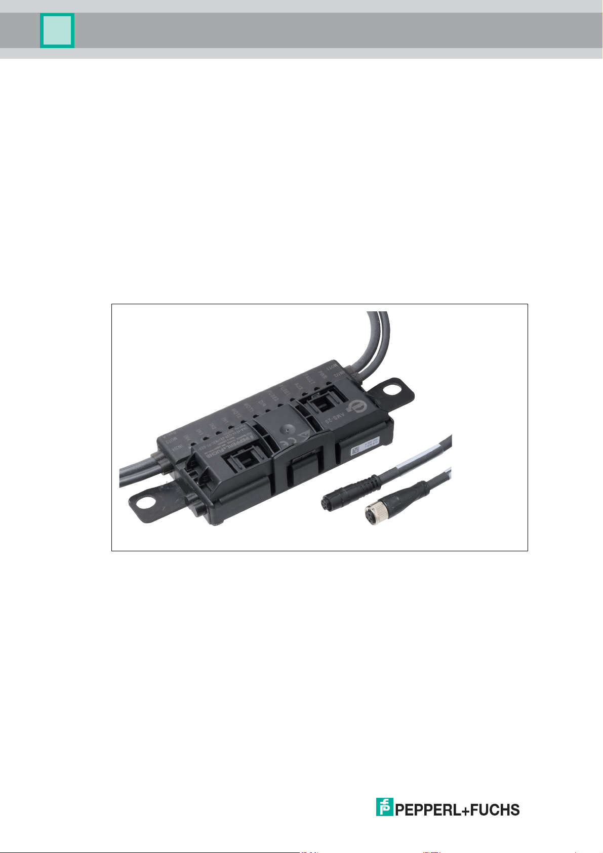
The VAA-4E4A-G20-ZEJ/M2L-P7-GEB motor control module is an AS-Interface connection
module for controlling 1 or 2 DC roller motors. The module is optimized for ITOH Denki
PM...XE/XP motors, but can also be used for compatible DC motors.
To record statuses in the field environment, the module also has 4 inputs for 3-wire sensors
with positive-switching outputs (PNP) or for mechanical contacts. The input characteristic of
the inputs corresponds to type 1 in accordance with EN 61131-2.
The motors are supplied with power via an external auxiliary voltage. Sensors a re supplied
from the AS-Interface. The auxiliary voltage is supplied to the motor control module via a 2nd
flat cable in addition to the AS-Interface flat cable.
■
The permissible auxiliary power is 18 V...30 V.
■
The sensor power supply may be loaded, in total, with 100 mA.
■
For each motor, a maximu m current load of 5 A is permitted briefly (<2 s).
Figure 2.1 VAA- 4E4A-G20-ZE J/M2 L-P7-GEB motor control module
Essential function and application characteristics of the motor control module are:
■
Compact housing for direct mounting in support profiles or cable ducts
■
Connection of the motors/sensors via cable outputs with M8 connectors
■
Piercing technology with gold-plated contact pins for contacting the AS-Interface flat cable
■
Function displays for the bus, external auxiliary voltage, status information, inputs, and
outputs
■
Communication m onitoring
■
Configurable start/stop ram ps for motor control
■
Supply of the connected motors from the external auxiliary voltage
■
Supply of the connected sensors from the AS-Interface
2018-09
6
Page 7
VAA-4E4A-G20-ZEJ/M2L-P7-GEB
53.3
13.5
27.2
152
3.5
18.6
100
136.5
138.5
15
27.5
YELLOW ASI
BLACK AUX
PWR
FAULT
AUX
FUSE1
FUSE2
DIR
MOT1
MOT2
IN1
IN2
IN3
IN4
IN1/3
MOT1
IN2/4
MOT2
Product Description
2.2 Housing
The housing is made entirely of plastic, with the exception of the hinge pins for the hinged cable
guide.
The main components are:
■
A mounting base with electronics coated in hot-melt adhesive
■
A folding guide cage as a cable guide for the AS-Interface flat cable.
Figure 2.2 Housing dimensions
2.3 Displays and Operating Elements
Figure 2.3 Status indic ations on the motor control module.
The operating status of the motor control module is displayed via 12 LEDs.
Status Indications for AS-Interface and Power Supply
The PWR LED and the FAULT LED show the AS-Interface operating status. Various error
statuses are displayed as a collective error message "Peripheral fault."
Display of the AS-Interface Operating Statuses
PWR LED, Green FAULT LED, Red Status
On Off AS-Interface power supply is OK
Flashing On Address = 0
On On AS-Interface communication error
2018-09
7
Page 8

VAA-4E4A-G20-ZEJ/M2L-P7-GEB
Product Description
PWR LED, Green FAULT LED, Red Status
Flashing Flashing Peripheral fault, collective error message for:
Off Off AS-Interface voltage missing
The AUX LED shows the status of the AUX external auxiliary voltage supply.
Display of the AUX External Auxiliary Voltage Supply
AUX LED
Red/green Status
Green on AUX external auxiliar y voltage is OK
Red on AUX external auxiliary voltage is inverted
Off AUX external auxiliary voltage is m issing
■
AUX external auxiliary power is missing or is
inverted
■
Overload of the sensor supply (IN+, IN-)
■
Overload of the speed signal SPEED
Status Indications for Motor Fuses
The FUSE1 LED for motor 1 and the FUSE2 LED for motor 2 show the status of the power
supplied to the motors.
Motor Fuse Indicator
LED FUSE1
LED FUSE2
Green Status
On Power supply for motor is O K
Off Power supply for motor is missing:
■
Fuse is faulty or
■
AUX external auxiliary voltage is not connected
Note!
Motor Fuses Are Safety Fuses
Fuses w ith a 5 A rated current act as protection against short circuits. Each motor is
safeguarded with a fuse. The fuses are not interchangeable. If a fuse is faulty, the module must
be replaced.
Status Indications for Motors MOT1, MOT2
The MOT1, MOT2, and DIR LEDs display information about the operating states of the
respective motor.
Motor Activity Indicators
LED MOT1
LED MOT2
Yellow Status
On Motor is in operation
Off Motor is off
2018-09
8
Page 9

VAA-4E4A-G20-ZEJ/M2L-P7-GEB
Product Description
Motor Direction of Rotation Indicator
LED DIR
Yellow Status
On Direction of rotation to the right (ITOH Denki)
Off Direction of rotation to the left (ITOH Denki)
Status Indicators for Sensors IN1, IN2, IN3, IN4
The LED IN1 for input 1, LED IN2 for input 2, LED IN3 for input 3, and LED IN4 for input 4
indicate the switch states of the inputs.
Display of the Inputs
LED IN1
LED IN2
LED IN3
LED IN4
Yellow Status
On Input is set (high)
Off Input is not set (low)
2.4 Interfaces and Connections
Flat Cable Specification
The AS-Interface motor control module is compatible with the AS-Interface standard cable in
accordance with IEC 62026-2.
The following AS-Interface cable types with "UL Recognized" approval are available:
AS-Interface Cable Types with UL Approval
Pepperl+Fuchs
Designation Color
VAZ-FK-R-YE Yellow TPE/TPE 2x 1.5 mm 2103
VAZ-FK-R-BK Black TPE/TPE 2x 1.5 mm 2103
VAZ-FK-PUR-YE Yellow PUR(TMPU)/TPM 2x 1.5 mm 20549
VAZ-FK-PUR-BK Black PUR(TMPU)/TPM 2x 1.5 mm 20549
Input/Output Connections
The sensors and motors are connected to the motor control module via cables with round M8
connectors:
Sheathing/wire
insulation material Cross section UL "Cable Style" Approval
■
Sensors: socket, 4-pin
■
Motors: socket, 5-pin
The cable length is 0.5 m.
2018-09
9
Page 10

VAA-4E4A-G20-ZEJ/M2L-P7-GEB
3 1
4 2
3 1
4 2
5
Product Description
Motor Supply from Auxiliary Power
The motors are supplied with power directly from the AUX external auxiliary power and this
cannot be switched. The voltage is always present at contacts 1 and 3 of the 5-pin M8
connector.
Connector Assignment
Connection for Connector
Sensor Input: in accordance w ith IEC/EN 61076-2-104
Motor Motor: in accordance with IEC/EN 61076-2-104
Connector type/assignment
M8, 4-pin, socket, screw-locking, coding A
Suitable counterpart connector:
M8, 4-pin, plug, screw-locking, coding A
IN1/IN3
1: IN+ sensor supply
2: IN3: Input
3: IN- sensor supply
4: IN1: Input
IN2/IN4
IN+ sensor supply
IN4: Input
IN- sensor supply
IN2: Input
M8, 5-pin, socket, screw-locking, coding B
Suitable counterpart connector:
M8, 5-pin, plug, screw-locking, coding B
1: MOT+ motor supply
2: DIR direction of rotation
3: MOT- (=AUX-) motor supply
4: RUN motor start
5: SPEED velocity signal
2018-09
10
Page 11

VAA-4E4A-G20-ZEJ/M2L-P7-GEB
Installation
3 Installation
3.1 Storage and Transport
For storage and transport purposes, package the unit using shockproof packaging material
and protect it against moisture. The best method of protection is to package the unit using the
original packaging. Furthermore, ensure that the ambient conditions are within allowable range.
3.2 Unpacking
Check the product for damage while unpacking. In the event of damage to the product, inform
the post office or parcel ser vice and notify the supplier.
Retain the original packaging in case the device must be stored or shipped again at a later
date.
Should you have any questions, please contact Pepperl+Fuchs.
3.3 Connecting the AS-Interface and Auxiliary Power Flat Cable
The motor control module is connected to the AS-Interface network and the AUX auxiliary
power via the AS-Interface flat cable. The yellow flat cable is for communication and the black
flat cable is for the AUX auxiliary power. The permissible auxiliary power is 18 V ... 30 V.
Contact between the motor control module and flat cables is established v ia two metal
mandrels and using insulation piercing technology. The flat cables are routed through a hinged
cable guide. When closed, the cable guide is locked using a locking bracket and can be
opened again without the needs for tools.
The profiled flat cables have a narrow upper side (with a visibly offset profile edge) and a wide
under side (profile edge not visible). The cable guide allows the flat cables to be inserted on
both sides, for flexible connection of flat cables already laid in cable ducts. However, you must
make sure that the profile edge always points to the motor control module. Mechanical reverse
polarity protection prevents complete closure of the cable guide if the flat cable is inserted
incorrectly.
Caution!
If one is inserted incorrectly, the motor control module will not work.
If the flat cable is inserted in the cable guide in the wrong direction, the voltage is inverted. The
motor control module will not work. H owever, internal electrical reverse polarity protection
protects it against breakage.
Connecting Flat Cables on the Narrow Side
The profile edge is visible from above.
1. Open the cable guide. To do this, push the locking bracket (1) slightly to one side.
2. Insert the black AUX flat cable with the profile edge (4) to the motor control module into the
lower guide (see the module tag "Black AUX").
3. Insert the yellow AS-Interface flat cable with the profile edge (3) to the motor control module
into the upper guide (see the module tag "YELLOW").
4. Make sure that the profile edges of both flat cables are under the respective reverse polarity
protection (2, 5).
5. Close the cable guide. It must engage securely in the locking bracket (1).
The metal mandrels contact the strands in the flat cables.
2018-09
11
Page 12

VAA-4E4A-G20-ZEJ/M2L-P7-GEB
YELLOW
BLACK AUX
1
2
3
5
4
Installation
Figure 3.1 Connecting Flat Cables on the Narrow Side
Connecting Flat Cables on the Wide Side
The profile edge is not visible from above. For orientation purposes in the figure below, the
edge is shown as a hidden edge drawn with a dotted line.
1. Open the cable guide. To do this, push the locking bracket (1) slightly to one side.
2. Insert the black AUX flat cable with the profile edge (3) to the motor control module into the
lower guide (see the module tag "Black AUX").
3. Insert the yellow AS-Interface flat cable with the profile edge (2) to the motor control module
into the upper guide (see the module tag "YELLOW").
4. Close the cable guide. It must engage securely in the locking bracket (1).
The profile edges (2, 3) of both flat cables are above the two reverse polarity protections.
The metal mandrels contact the strands in the flat cables.
12
2018-09
Page 13

VAA-4E4A-G20-ZEJ/M2L-P7-GEB
YELLOW
BLACK AUX
1
23
1
2
Installation
Figure 3.2 Connecting flat ca bles on the wide side (p rofile edge as dotted line)
Flat Cable Inserted Incorrectly
The figure below shows an incorrectly inserted flat cable. The profile edge (2) does not point to
the motor control module; the flat cable is therefore inserted with reverse polarity. The flat cable
is located on the reverse polarity protection (1) with a curvature, which means that the cable
guide cannot be closed completely (mechanical reverse polarity protection).
2018-09
Figure 3.3 Flat cable inserted incorrectly (profile edge as dotted line)
13
Page 14

VAA-4E4A-G20-ZEJ/M2L-P7-GEB
PWR
AUX+
AUX-
AS-Interface +
AS-Interface -
FAULT
AUX
1
4
3
2
IN
1
2
4
5
3
FUSE
IN1/3
IN+
IN1
ININ3
IN2/4
IN+
IN2
ININ4
MOT1 & MOT2
MOT+
DIR
RUN
SPEED
MOT-
3 1
4 2
M
3 1
4 2
5
DIR
MOT
Installation
3.4 Connecting Motors and Sensors
Figure 3.4 Connection wiring diagram for motors and sensors
14
2018-09
Page 15

VAA-4E4A-G20-ZEJ/M2L-P7-GEB
Commissioning
4 Commissioning
4.1 AS-Interface Communication
Assigning the AS-Interface Data Bits
4 data bits are available for communication between the motor control module and the m aster
and 4 data bits are available for controlling the motors.
The following designations apply below:
■
DI0...DI3 for AS-Interface input data (motor control module to master)
■
DO0...DO 3 for AS-Interface output data (master to motor control module)
DI0...DI3 motor control module to master
AS-Interface data bit Input DI
DI0 Switch state input IN1
DI1 Switch state input IN2
DI2 Switch state input IN3
DI3 Switch state input IN4
DO0...DO3 Master to Motor Control Module
AS-Interface data bit Output DO
DO0 Start/stop motor 1
DO1 Start/stop motor 2
DO2 Direction of rotation of motor 1 and motor 2
DO3 Slow rotation speed of motor 1 and motor 2
AS-Interface Communication Monitoring
The motor control module has a watchdog function. If there has been no communication with
the master for more than 40 ms, the motor control module sets the output data DO0...DO3 to
logical 0.
Starting/Stopping the Motors (DO0, DO1)
You can start or stop the motors separately via bits DO 0 and DO1. To start the motors, you
must set the corresponding data bit to logical 1. Via the shared SPEED control signal, the
motor control module uses an analog voltage value to actuate the respective motor that has
been switched on. The SPEED control signal is released for the relevant output only when data
bit DO0 or DO 1 is set. The analog voltage value corresponds to the set speed.
Data Bits DO0, DO1
Data bit State Function Motor start signal RUN LED MOT1/2
DO0 1 Start motor 1 1: ≥ (U
0 Stop motor 1 MOT1: off
DO1 1 Start motor 2 MOT2: on
0 Stop motor 2 MOT2: off
0: high impedance
- 2.5 V) in no-load operation
AUX
MOT1: on
2018-09
15
Page 16

VAA-4E4A-G20-ZEJ/M2L-P7-GEB
Commissioning
Switching the Motor Direction of Rotation (DO2)
You can switch the direction of rotation of the motors using the DIR control signal. The direction
of rotation signal applies to both motors. To control the direction of location, you must
param eterize data bit DO2 accordingly.
For ITOH Denki, logical 0 corresponds to a direction of rotation to the left. The motor control
module sw itches the DIR control signal to high impedance.
For ITOH Denki, logical 1 corresponds to a direction of rotation to the right. The m otor control
module sw itches the DIR control signal to AUX level.
Data Bit DO2
Data bit State Function DIR direction of rotation signal LED DIR
DO2 0 Direction of rotation left High impedance, approx. 0 V Off
1 Direction of rotation right ≥ (U
operation
Switching the Motor Speed (DO3)
- 2.5 V) in no-load
AUX
On
You can switch both motors to a slow speed via data bit DO3. The slow speed is determined
based on the set speed.
Data Bit DO3
Data bit State Function
DO3 0 Fast speed
1 Slow speed
Adjusting the Motor Speed (P0 ... P2)
You can adjust the speed via parameter bits P0...P2. This always applies to both motors
simultaneously. To do this, you must pa rameterize 1 of 8 predefined speed values. The speed
values correspond to analog voltage values.
If the master does not change the parameter bits when the AS-Interface network is switched
on, the 8th speed value (9.7 V) is set by default on the motor control module.
Geschwindigkeitswert (9,7 V) voreingestellt.
Using data bit DO3, you can switch the speed of both motors between fast and slow.
The motor control module issues the set control voltage to the motors via the SPEED control
signal as soon as the motors are switched on via data bits DO0 and DO1 (logical 1). The
control voltage is readjusted by the motor control module and is therefore independent of the
load within certain limits. If the control limits are exceeded due to an excessive load, the motor
control module issues a peripheral fault.
Parameter Bits P0 ... P2
DO0 (MOT1)
P2 P1 P0
x x x 0 < 1 V < 1 V
0 0 0 1 2.7 V 0.7 V
0 0 1 1 3.7 V 0.7 V
0 1 0 1 4.7 V 1.7 V
0 1 1 1 5.7 V 1.7 V
1 0 0 1 6.7 V 2.7 V
1 0 1 1 7.7 V 2.7 V
or DO 1 (MOT2)
Speed signal U
Fast (D3=0) Slow (D3=1)
S
16
2018-09
Page 17

VAA-4E4A-G20-ZEJ/M2L-P7-GEB
Commissioning
DO0 (MOT1)
P2 P1 P0
1 1 0 1 8.7 V 3.7 V
1 1 1 1 9.7 V 4.7 V
or DO1 (MOT2)
Speed signal U
Fast (D3=0) Slow (D3=1)
S
Default setting
Reversing the Direction of Rotation of MOT2 (P3)
You can reverse the direction of rotation of MOT2 via parameter bit P3.
Parameter Bit P3
Parameter bit State Function
P3 0 counter-rotating; direction of rotation of MOT2 inverted
1 synchronized, direction of rotation of MOT1 = direction of rotation of MOT2
(Default setting)
Status of Sensor Inputs (DI0 ... DI3)
The motor control module transfers the switch states of inputs IN1 to IN4 to the master via data
bits DI0 (IN 1) to DI3 (IN4).
There is a filter upstream of the inputs that suppresses pulses ≤ 2 ms.
Data Bits DI0 ... DI3
Data bit State Input switching status LEDs IN1 ... IN 4
DI0 0 Unattenuated, IIN ≤ 0.5 mA IN1: off
1 Attenuated, IIN ≥ 2.0 mA IN1: on
DI1 0 Unattenuated, IIN ≤ 0.5 mA IN2: off
1 Attenuated, IIN ≥ 2.0 mA IN2: on
DI2 0 Unattenuated, IIN ≤ 0.5 mA IN3: off
1 Attenuated, IIN ≥ 2.0 mA IN3: on
DI3 0 Unattenuated, IIN ≤ 0.5 mA IN4: off
1 Attenuated, IIN ≥ 2.0 mA IN4: on
4.2 Configuring the Start/Stop Ramps
Overview
To control the acceleration and to stop the motors, you can set 1 of 8 defined start/stop ramps
for the speed signal SPEED. These ramps always apply to both m otors simultaneously. The
ramp duration corresponds to the time from stopped to reaching the maximum speed or from
the maximum speed to stopped. The inclines of the ramps are constant for each of the 8 ramps
and independent of the set speed. The reference value for all ramps is the speed signal
SPEED = 9.7 V. For a lower parameterized speed, the ramp duration is proportionally shorter.
2018-09
17
Page 18

VAA-4E4A-G20-ZEJ/M2L-P7-GEB
Commissioning
Predefined Start/Stop Ramps
Ramp no. Ramp duration
0 no ramp
1 50 ms
2 100 ms
3 200 ms
4 300 ms
5 500 ms (default setting)
6 1000 ms
7 1500 ms
The ramp is not effective if the direction of rotation signal is switched when the motor is active.
In this case, the direction of rotation is reversed immediately.
Note!
Default Setting on Delivery
On outbound delivery, ramp no. 5 (500 ms) is the default.
Configuring Start/Stop Ramps
To adjust a start/stop ram p, you must change the motor control module to configuration mode.
The motor control module stores a new ramp configuration in the internal non-volatile memory.
This ramp is activated automatically after each switch-on. You can reconfigure a ram p as often
as required.
A prerequisite for configuration is that the flat cables for the AS-Interface and AUX are
connected. Communication must already be taking place between the master and motor
control module.
Note!
Configuration Mode Display via LEDs
If the motor control module is in configuration mode, the MOT1 and MOT2 LEDs flash
simultaneously at a frequency of approx. 2 Hz .
The configuration sequence consists of 9 steps. As part of this, defined data is transferred via
data bits DO0 ... DO3 and parameter bits P0... P3 between the m aster and the motor control
module. The master must keep the data and param eter bits constant for at least 10 ms for each
step. Longer intervals are possible as long as a period of 10 s is not exceeded for steps 1...6.
Configuring a new start/stop ramp involves the following phases:
■
In steps 1 ... 6, the master sends param eter values to the motor control module to activate
configuration mode (max. 10 s). For each step, DO0 ... DO3 must have the data value "4."
■
As soon as the motor control module is in configuration m ode, the 2 MOT1 and MOT2
LEDs start to flash.
18
■
In step 7, the master sends the selected ramp no. via DO0 ... DO3 to the motor control
module.
■
In step 8, the master sends the parameter value "4" via P0 ... P3 to the motor control
module. The motor control module stores the ram p number in the non-volatile memory.
■
In step 9, the master exits configuration mode. It sends the data value "4" via DO0 ... DO3
and the data value "7" via P0 ... P3. The motor control module switches to normal mode.
The MOT1 and MOT2 LEDs stop flashing.
2018-09
Page 19

VAA-4E4A-G20-ZEJ/M2L-P7-GEB
Commissioning
Note!
Sequence for Com mand Transmission
For each step, you generally send the data value via DO0 ... D03 first, and then the parameter
value P0 ... P3. The following table depicts the contexts of the communication between the
master and the motor control module. The value "x" represents any of the values in the table.
Sequence for Configuring a Start/Stop Ramp
Send the following data values and parameter values to the motor control module:
1. For each of steps 1...6, send the data value "4" via DO0 ... DO3 as well as, via P0 ... P3, the
corresponding value from the parameter sequence 3,1,6,3,1,6.
2. If configuration mode is active, as step 7, send the required ramp no. via DO0 ... DO3 and
via P0 ... P3 the parameter value "6."
3. As step 8, send the ramp no. again via DO0 ... DO3 and via P0 ... P3 the parameter value
"4."
4. As step 9 send data value "0" via DO0 ... DO3 and via P0 ... P3 the parameter value "7."
The motor control module has stored the new start/stop ramp and switched back to
normal mode.
Contexts of Module Communication
Step DO0...DO3 P0...P3 Comment
≠ 4 x Motor control module in normal mode
1 4 3 Start activation sequence for configuration mode
2 4 1
3 4 6
4 4 3
5 4 1
6 4 6 End activation sequence for configuration mode.
7 Ramp no. 6 Transfer of the ramp number to the motor control module
8 Ramp no. 4 The ramp is stored
9 0 7 Motor control module switches back to normal mode
Troubleshooting during Configuration
The following table describes the behavior of the motor control module if a fault occurs during
the 9-step configuration process.
Fault Scenarios
Step Possible fault Motor control module reaction
1 ... 6
7 or 8 Incorrect data or parameter values
2018-09
■
Incorrect data or parameter values or
■
steps 1 to 6 take longer than 10 s
Motor control module remains in normal mode
■
The motor control module changes to
normal operation only when the master
sends "0" via DO0 ... DO3 and "7" via P0 ...
P3.
■
If "0" or "7" has already been set by the
master in one of these steps, the motor
control module switches directly to normal
operation. The stored ramp is not
changed.
19
Page 20

VAA-4E4A-G20-ZEJ/M2L-P7-GEB
Troubleshooting
5 Troubleshooting
Fault Information and Remedy
Error LED indicator Possible cause Remedy
No data
communication
with AS-Interface
master
Motors will not
start
Sensors or
inputs IN1 ... IN4
not working
PWR off AS-Interface voltage is missing or is
inverted
PWR flashes and
FAULT on
PWR on and
FAULT on
AUX off AUX external power supply is
AUX red on AUX external power supply is
AUX green on
and
FUSE1 (motor 1)
off and/or FUSE2
(motor 2) off
PWR and FAULT
flash alternately
PWR and FAULT
flash alternately
Module address is 0 Program module address
AS-Interface Master is not switched
on (offline) or
There is duplicate addressing
missing
inverted
Motor fuse is faulty due to
overloading of the motor supply
Peripheral fault "Overload speed
signal SPEED:"
Motor, motor cable, or motor control
module is faulty
Peripheral fault: overload on sensor
supply
Check AS-Interface wiring
Switch on the AS-Interface master
or
Check the addresses of all modules
on the AS-Interface segment
Check AUX voltage and AUX flat
cable
Correct the polarity of the AUX flat
cable in the cable guide
Replace the m otor control module
(cannot be repaired) and remove
the cause of the overload before
starting the motor again
Replace motor or motor control
module
Check the sensors and eliminate
the overload
20
2018-09
Page 21

FACTORY AUTOMATION –
SENSING YOUR NEEDS
Worldwide Headquarters
Pepperl+Fuchs GmbH
68307 Mannheim · Germany
Tel. +49 621 776-0
E-mail: info@de.pepperl-fuchs.com
USA Headquarters
Pepperl+Fuchs Inc.
Twinsburg, Ohio 44087 · USA
Tel. +1 330 4253555
E-mail: sales@us.pepperl-fuchs.com
Asia Pacific Headquarters
Pepperl+Fuchs Pte Ltd.
Company Registration No. 199003130E
Singapore 139942
Tel. +65 67799091
E-mail: sales@sg.pepperl-fuchs.com
www.pepperl-fuchs.com
Subject to modifications
Copyright PEPPERL+FUCHS • Printed in Germany
/ DOCT-6161
09/2018
 Loading...