

Page 1
Instruction Manual
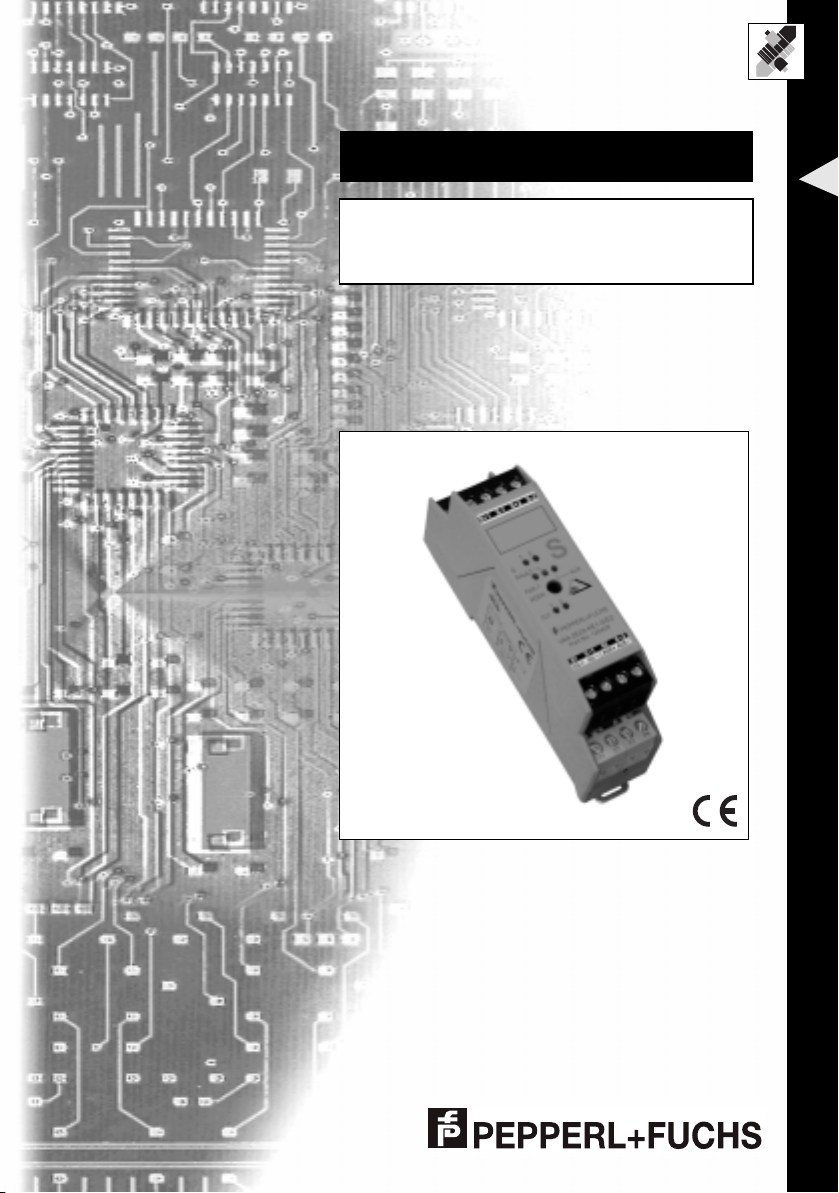
AS-Interface Safety at Work
VAA-2E2A-KE1-S/E2
Version 1.0
FACTORY AUTOMATION
Page 2

With regard to the supply of products, the current issue of the following document is applicable: The General
published by the Ce ntral Association of the "Elektrotechnik und Elektroindustrie (ZVEI) e.V.
in their most recent version as well as the supplementary clause: "Extended reservation of title".
For this reason, this printed matter is produced on paper bleached without the use of chlorine.
Terms of Delivery for Products and Services of the Electrical Industry,
We at Pepperl+Fuchs recognise a duty to make a contribution to the future,
Page 3

VAA-2E2A-KE1-S/E2
S
Table of contents
1 Declaration of conformity . . . . . . . . . . . . . . . . . . . . . . . . . . . . . . . . . . . . 2
2 Symbols used in this document . . . . . . . . . . . . . . . . . . . . . . . . . . . . . . . 3
3 Safety . . . . . . . . . . . . . . . . . . . . . . . . . . . . . . . . . . . . . . . . . . . . . . . . . . . . 4
3.1 Intended use . . . . . . . . . . . . . . . . . . . . . . . . . . . . . . . . . . . . . . . . . . . . . . . . . . . . . . 4
3.1.1 Non-secure outputs . . . . . . . . . . . . . . . . . . . . . . . . . . . . . . . . . . . . . . . . . . . . . . . . . 4
3.1.2 Requirements for the safety monitor . . . . . . . . . . . . . . . . . . . . . . . . . . . . . . . . . . . . 4
3.1.3 Requirements for wiring . . . . . . . . . . . . . . . . . . . . . . . . . . . . . . . . . . . . . . . . . . . . . . 4
3.1.4 Switches or sensors . . . . . . . . . . . . . . . . . . . . . . . . . . . . . . . . . . . . . . . . . . . . . . . . . 5
3.2 General safety instructions . . . . . . . . . . . . . . . . . . . . . . . . . . . . . . . . . . . . . . . . . 5
3.3 Transfer time of the safety-relevant information . . . . . . . . . . . . . . . . . . . . . . . . 5
3.4 PFD-calculation . . . . . . . . . . . . . . . . . . . . . . . . . . . . . . . . . . . . . . . . . . . . . . . . . . . 5
4 Working principles of the module . . . . . . . . . . . . . . . . . . . . . . . . . . . . . 6
4.1 Safety related inputs . . . . . . . . . . . . . . . . . . . . . . . . . . . . . . . . . . . . . . . . . . . . . . . 6
4.2 Non-secure outputs . . . . . . . . . . . . . . . . . . . . . . . . . . . . . . . . . . . . . . . . . . . . . . . . 7
5 Connections and displays . . . . . . . . . . . . . . . . . . . . . . . . . . . . . . . . . . . . 8
5.1 Connections . . . . . . . . . . . . . . . . . . . . . . . . . . . . . . . . . . . . . . . . . . . . . . . . . . . . . . 8
5.2 Displays . . . . . . . . . . . . . . . . . . . . . . . . . . . . . . . . . . . . . . . . . . . . . . . . . . . . . . . . . 9
6 Interface properties . . . . . . . . . . . . . . . . . . . . . . . . . . . . . . . . . . . . . . . . 10
6.1 AS-Interface, auxiliary energy . . . . . . . . . . . . . . . . . . . . . . . . . . . . . . . . . . . . . . 10
6.2 Inputs . . . . . . . . . . . . . . . . . . . . . . . . . . . . . . . . . . . . . . . . . . . . . . . . . . . . . . . . . . 10
6.2.1 General . . . . . . . . . . . . . . . . . . . . . . . . . . . . . . . . . . . . . . . . . . . . . . . . . . . . . . . . . 10
6.2.2 Safety category . . . . . . . . . . . . . . . . . . . . . . . . . . . . . . . . . . . . . . . . . . . . . . . . . . . 11
6.2.3 Cross fault monitoring . . . . . . . . . . . . . . . . . . . . . . . . . . . . . . . . . . . . . . . . . . . . . . 11
6.3 Outputs . . . . . . . . . . . . . . . . . . . . . . . . . . . . . . . . . . . . . . . . . . . . . . . . . . . . . . . . . 11
7 Commissioning . . . . . . . . . . . . . . . . . . . . . . . . . . . . . . . . . . . . . . . . . . . 13
7.1 Requirements for configuring the safety monitor . . . . . . . . . . . . . . . . . . . . . . 13
7.2 Installation . . . . . . . . . . . . . . . . . . . . . . . . . . . . . . . . . . . . . . . . . . . . . . . . . . . . . . 13
7.3 Addressing modules . . . . . . . . . . . . . . . . . . . . . . . . . . . . . . . . . . . . . . . . . . . . . . 13
7.4 Function test . . . . . . . . . . . . . . . . . . . . . . . . . . . . . . . . . . . . . . . . . . . . . . . . . . . . 13
7.5 Operating modes . . . . . . . . . . . . . . . . . . . . . . . . . . . . . . . . . . . . . . . . . . . . . . . . . 13
8 Operation of AS-Interface safety modules . . . . . . . . . . . . . . . . . . . . . . 14
9 Certificates . . . . . . . . . . . . . . . . . . . . . . . . . . . . . . . . . . . . . . . . . . . . . . . 14
A Application examples . . . . . . . . . . . . . . . . . . . . . . . . . . . . . . . . . . . . . . 15
A.1 Category 2 . . . . . . . . . . . . . . . . . . . . . . . . . . . . . . . . . . . . . . . . . . . . . . . . . . . . . . 15
A.2 Category 3 . . . . . . . . . . . . . . . . . . . . . . . . . . . . . . . . . . . . . . . . . . . . . . . . . . . . . . 16
A.3 Category 4 . . . . . . . . . . . . . . . . . . . . . . . . . . . . . . . . . . . . . . . . . . . . . . . . . . . . . . 18
B Summery of the requirements for categories . . . . . . . . . . . . . . . . . . . 20
Date of Issue 2003-11-28
ubject to reasonable modifications due to technical advances. Copyright Pepperl+Fuchs, Printed in Germany
Pepperl+Fuchs Group • Tel.: Germany +49 621 776-0 • USA +1 330 4253555 • Singapore +65 67799091 • Internet http://www.pepperl-fuchs.com
1
Page 4
VAA-2E2A-KE1-S/E2
S
Declaration of conformity
1 Declaration of conformity
The AS-Interface safety module VAA-2E2A-KE1-S/E2 with 2 safety-related inputs for
mechanical switches and 2 non-safety related outputs was developed and manufactured in observance of applicable European standards and regulations.
A corresponding declaration of conformity can be requested from the
manufacturer.
The manufacturer of the product, Pepperl+Fuchs GmbH in D-68307 Mannheim, has
a certified quality assurance program in accordance with ISO 9001.
ISO
9001
Date of Issue 2003-11-28
ubject to reasonable modifications due to technical advances. Copyright Pepperl+Fuchs, Printed in Germany
2
Pepperl+Fuchs Group • Tel.: Germany +49 621 776-0 • USA +1 330 4253555 • Singapore +65 67799091 • Internet http://www.pepperl-fuchs.com
Page 5
S
2 Symbols used in this document
This symbol warns of danger .
In the event the warning is ignored, the consequences may range from
personal injury to death of persons or from damage to destruction of
equipment.
This symbol warns of a possible fault.
Failure to observe may result in damage to the device or systems and
installations connected to it up to and including compete lack of proper
functionality.
This symbol brings important information to your attention.
VAA-2E2A-KE1-S/E2
Symbols used in this document
Date of Issue 2003-11-28
ubject to reasonable modifications due to technical advances. Copyright Pepperl+Fuchs, Printed in Germany
Pepperl+Fuchs Group • Tel.: Germany +49 621 776-0 • USA +1 330 4253555 • Singapore +65 67799091 • Internet http://www.pepperl-fuchs.com
3
Page 6
VAA-2E2A-KE1-S/E2
S
Safety
3 Safety
3.1 Intended use
The AS-Interface safety module described here, when used properly in combination
with an AS-Interface safety monitor programmed appropriately, allows for operation
of sensor-controlled devices for protection of persons up to Category 4 according to
EN 954-1 or up to SIL 3 according to EN/IEC 61508.
Protection of operating personnel and the system is not ensured if the
module is not used in accordance with its intended purpose.
3.1.1 Non-secure outputs
The outputs must not be used for safety-related functions.
3.1.2 Requirements for the safety monitor
The module must only be used in a proper manner as a safety-related slave on an
AS-Interface line with the corresponding AS-i safety monitor. The AS-Interface safety
monitor must meet the requirements of the system specification "Specification of safe
AS-Interface transfer" Version 2.01 dated May12, 2000.
All components must be evaluated for functionality according to this safety standard
for the evaluation of a safety-related function.
The correct execution of the desired safety function also depends on the wiring and
programming of the safety monitor. This also applies to the desired safety response
after a code malfuntion or failure. See also the documentation for the safety monitor.
The safety function (including all safety-related sensors) must be tested before it is
placed in service the first time.
3.1.3 Requirements for wiring
The requirements of EN/IEC 60204-1 (or similar standard) must always be observed.
The requirements for external wiring and the selection of sensors that are connected
are based on both the functionality to be provided as well as the required category
(EN 954-1/ISO 13849-1 or EN/IEC 61508). The category can be determined by
means of a risk analysis (for example as described by EN1050) or can be derived
from a C standard. The category or SIL of the safety monitor must at least correspond
to the category or SIL required by the application.
Date of Issue 2003-11-28
ubject to reasonable modifications due to technical advances. Copyright Pepperl+Fuchs, Printed in Germany
4
Pepperl+Fuchs Group • Tel.: Germany +49 621 776-0 • USA +1 330 4253555 • Singapore +65 67799091 • Internet http://www.pepperl-fuchs.com
Page 7
VAA-2E2A-KE1-S/E2
S
3.1.4 Switches or mechanical contacts
The switches must either be of the forced-opening variety or must have a defined failure behaviour. Combinations of switches that ensure comparable safety (error behaviour analysis) can be used.
3.2 General safety instructions
Any type of operation other than what is described in the instructions
places the safety and functionality of the module and connected systems in question.
The module can only be operated by trained professionals in accordance with the
available instruction manual (see section 8).
Connecting modules and performing maintenance tasks while the devices are connected to a power source must only be performed by trained electrical specialists.
If malfunctions cannot be eliminated, the module must be taken out of operation and
protected from being inadvertently placed back in operation.
Repairs must only be performed directly by the manufacturer.
Making changes to or tampering with the device is not permitted and will render the
warranty void.
When operating the device, care must be taken to ensure that the requirements for
installation of a housing in IP20 are also maintained.
The plant management is responsible for heeding local safety regulations.
Safety
3.3 Transfer time of the safety-relevant information
The transfer time depends essentially on the monitor. The corresponding documentation and the switch-off times of the actuators must be observed.
3.4 PFD-calculation
To calculate the PFD (probability of failure on demand) of a safety-related function, all
PFD values of all components used in this function must be taken into consideration.
The AS-Interface safety slave does not make any significant contribution to the PFD
or PDH (probability of dangerous failure per hour) of the overall system.
For the PFD or PFH-values of other components, especially of the safety monitor,
please refer to the relevant documentation.
Date of Issue 2003-11-28
ubject to reasonable modifications due to technical advances. Copyright Pepperl+Fuchs, Printed in Germany
Pepperl+Fuchs Group • Tel.: Germany +49 621 776-0 • USA +1 330 4253555 • Singapore +65 67799091 • Internet http://www.pepperl-fuchs.com
5
Page 8
VAA-2E2A-KE1-S/E2
S
Working principles of the module
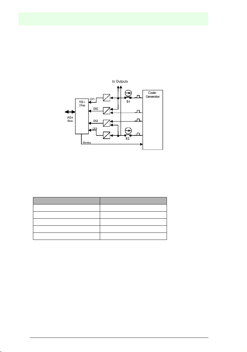
4 Working principles of the module
4.1 Safety related inputs
The module generates a code sequence internally. This code sequence is monitored
by a safety monitor (an additional bus station) for the correct sequence.
.
Figure 4.1: Code generation
The transfer of the code sequence is affected by the status of the externally connected mechanical switch.
Information on the activation of the connected mechanical switches (e. g. for emergency stop button activated, code transfer interrupted) is transferred as follows:
Activated input channel Code
DI3 DI2 DI1 DI0
1XX00
200XX
1 and 2 0 0 0 0
none X X X X
Code words 0000, XX00 and 00XX cause the safety monitor to bring the system to a
secure state (for example with the emergency stop button) without reporting a malfunction. If a bit of a code word deviates from the nominal code word, the safety monitor switches the system into the secure state and signals a malfunction of the slave.
The two input channels of the safety module are independent of each other. Parameters can be set in the safety monitor for monitoring the synchronicity of the two inputs
for two-channel applications. For more information, see also the application examples
in Appendix A.
Date of Issue 2003-11-28
ubject to reasonable modifications due to technical advances. Copyright Pepperl+Fuchs, Printed in Germany
6
Pepperl+Fuchs Group • Tel.: Germany +49 621 776-0 • USA +1 330 4253555 • Singapore +65 67799091 • Internet http://www.pepperl-fuchs.com
Page 9

VAA-2E2A-KE1-S/E2
S
Working principles of the module
.
Figure 4.2: Example: An emergency off button with two separate circuits is assigned to both module inputs.
4.2 Non-secure outputs
The outputs are designed according to the AS-Interface standard. These are switched
to positive potential (PNP technology).
The state of the outputs is set according to the operating mode, which in turn is adjusted by parameter on the AS-Interface master, either switched by the master or derived from the states of the inputs. For a more detailed description, see section 6.3.
Date of Issue 2003-11-28
ubject to reasonable modifications due to technical advances. Copyright Pepperl+Fuchs, Printed in Germany
Pepperl+Fuchs Group • Tel.: Germany +49 621 776-0 • USA +1 330 4253555 • Singapore +65 67799091 • Internet http://www.pepperl-fuchs.com
7
Page 10

VAA-2E2A-KE1-S/E2
S
Connections and displays
5 Connections and displays
.
S+1 S-1 S+2 S-2
1
S
FAULT
PWR
ADDR
OUT
01
AS-i AS-i
5.1 Connections
Safety related inputs Outputs and others
Designation Description Designation Description
S1+ Mechanical switch 1+ O1 Output 1+
S1+- Mechanical switch 1- O-1 Output 1-
S2+ Mechanical switch 2+ O2 Output 2+
S2- Mechanical switch 2- O-2 Output 2-
S
AUX
122
01
02
02
AUX AUX
++
ASi+ AS-Interface +
ASi- AS-Interface -
AUX+ Auxiliary power U
AUX- Auxiliary power U
AUX
AUX
+
-
Date of Issue 2003-11-28
ubject to reasonable modifications due to technical advances. Copyright Pepperl+Fuchs, Printed in Germany
8
Pepperl+Fuchs Group • Tel.: Germany +49 621 776-0 • USA +1 330 4253555 • Singapore +65 67799091 • Internet http://www.pepperl-fuchs.com
Page 11

VAA-2E2A-KE1-S/E2
S
Connections and displays
5.2 Displays
Designation Description Designation Description
S1 Yellow LED,
switching state of input
circuit 1
S2 Yellow LED,
switching state of input
circuit 2
PWR Green LED,
AS-Interface power
FAULT Red LED,
AS-Interface communication error
AUX Green LED,
auxiliary power
OUT1 Yellow LED,
switching state of
output 1, U
through with active LED
OUT2 Yellow LED,
switching state of
output 2, U
through with active LED
+ switched
AUX
+ switched
AUX
Date of Issue 2003-11-28
ubject to reasonable modifications due to technical advances. Copyright Pepperl+Fuchs, Printed in Germany
Pepperl+Fuchs Group • Tel.: Germany +49 621 776-0 • USA +1 330 4253555 • Singapore +65 67799091 • Internet http://www.pepperl-fuchs.com
9
Page 12

VAA-2E2A-KE1-S/E2
S
Interface properties
6 Interface properties
6.1 AS-Interface, auxiliary energy
In case of the KE1-series all interfaces are connected via removable terminals. Thus
also AS-Interface and auxiliary energy. The cable has to meet the minimum requirements for AS-Interface (e.g. AS-Interface flat band cable, VAZ-FK-S-YE for AS-Interface and VAZ-FK-S-BK for auxiliary energy).
6.2 Inputs
6.2.1 General
In this case the switches are also connected to removable terminals. One or more mechanical switches, switched in series, can be connected per channel.
.
Figure 6.1: 2 mechanical switches (or one two-channel switch)
.
Figure 6.2: 1 mechanical switch
If only one single-channel switch is used, input 1 must be used for this purpose. If input 2 is to remain unswitched, it must be jumpered.
Date of Issue 2003-11-28
ubject to reasonable modifications due to technical advances. Copyright Pepperl+Fuchs, Printed in Germany
10
Pepperl+Fuchs Group • Tel.: Germany +49 621 776-0 • USA +1 330 4253555 • Singapore +65 67799091 • Internet http://www.pepperl-fuchs.com
Page 13

VAA-2E2A-KE1-S/E2
S
Interface properties
6.2.2 Safety category
The module contains two input channels independent of each other and redundantly
structured that individually meet the requirements of Category 4 according to
EN 954-1.
6.2.3 Cross fault monitoring
The inputs are monitored for cross fault with each other. Cross fault monitoring is capable of detecting low-resistance cross faults between the two inputs caused by a metallic connection.
6.3 Outputs
The outputs are designed according to the AS-Interface standard. These are switched
to positive potential (PNP technology).
The outputs can be operated in two modes:
1. The outputs are controlled directly by the corresponding data bits of the AS-Interface master.
2. The output signals of the AS-Interface master are linked with the secure inputs. The
outputs are turned on if the master turns them on or if the inputs are in a secure
state.
This operating mode is used to control signal lights that must display the state of
the inputs without the master being involved.
.
Figure 6.3: Output modes
Date of Issue 2003-11-28
ubject to reasonable modifications due to technical advances. Copyright Pepperl+Fuchs, Printed in Germany
Pepperl+Fuchs Group • Tel.: Germany +49 621 776-0 • USA +1 330 4253555 • Singapore +65 67799091 • Internet http://www.pepperl-fuchs.com
11
Page 14

VAA-2E2A-KE1-S/E2
S
Interface properties
Modes and logic table of the outputs
The modes are selected by the Master with parameter bit P0:
P0
S1 / S2 1)DO0 / DO1
1
X / X 0 / 0 0 / 0
X / X 1 / 1 1 / 1
2)
OUT1 / OUT2 Mode
Outputs independent of
inputs
Open switch at the input
0 / 0 X / X 1 / 1
0
1 / 1 0 / 0 0 / 0 When the switches are
1 / 1 1 / 1 1 / 1
1)
0 corresponds to an open switch (secure state). 1 means closed switch.
X means any state that has no effect on the outputs.
2)
1 means outputs are turned on, 0 means outputs are voltage-free.
sets the corresponding
output
closed on the input, the
master controls the output
Date of Issue 2003-11-28
ubject to reasonable modifications due to technical advances. Copyright Pepperl+Fuchs, Printed in Germany
12
Pepperl+Fuchs Group • Tel.: Germany +49 621 776-0 • USA +1 330 4253555 • Singapore +65 67799091 • Internet http://www.pepperl-fuchs.com
Page 15

VAA-2E2A-KE1-S/E2
S
Commissioning
7 Commissioning
7.1 Requirements for configuring the safety monitor
On measures related to the safety monitor that are required for organisation, please
refer to the safety monitor documentation.
7.2 Installation
For installation of the module a suitable top hat DIN rail in accordance with DIN 50022
is recommended.
7.3 Addressing modules
Addressing of the module is performed by means of a manual addressing device or
with an AS-Interface master. If a manual addressing device is used, it should be connected and addressed to the addressing socket of the module (identified with ADDR)
using the addressing cable included with delivery. Addresses from 1 to 31 can be assigned. The state as supplied is address 0.
7.4 Function test
Function tests must be performed as part of the installation. Because of the cross fault
monitoring of the secure inputs, there is no need for a test for short circuits in the wiring. The function test covers all faults present at the time of installation.
7.5 Operating modes
No operating modes can be switched for the inputs. The parameters in the AS-Interface can affect the behaviour of the outputs. For a more detailed description of connecting peripheral devices, consult section 5.
Date of Issue 2003-11-28
ubject to reasonable modifications due to technical advances. Copyright Pepperl+Fuchs, Printed in Germany
Pepperl+Fuchs Group • Tel.: Germany +49 621 776-0 • USA +1 330 4253555 • Singapore +65 67799091 • Internet http://www.pepperl-fuchs.com
13
Page 16

VAA-2E2A-KE1-S/E2
S
Certificates
8 Operation of AS-Interface safety modules
The safety function of the module is determined by how the monitor is programmed.
Please observe the corresponding documentation. Depending on the safety category,
regular function tests may not be required.
9 Certificates
Approvals according to EN 954-1/ISO 13849-1 and EN/IEC 61508.
Date of Issue 2003-11-28
ubject to reasonable modifications due to technical advances. Copyright Pepperl+Fuchs, Printed in Germany
14
Pepperl+Fuchs Group • Tel.: Germany +49 621 776-0 • USA +1 330 4253555 • Singapore +65 67799091 • Internet http://www.pepperl-fuchs.com
Page 17

VAA-2E2A-KE1-S/E2
S
Application examples
A Application examples
The examples listed here correspond to our understanding of the categories according to EN 954-1 and should not be seen as binding.
A.1 Category 2
The safety function(s) must be tested at appropriate intervals of time by the machine
control system. Loss of the safety function will be detected by the test. The test intervals must be adjusted to match the application.
Connecting two independent mechanical position switches of Category 2:
.
Date of Issue 2003-11-28
ubject to reasonable modifications due to technical advances. Copyright Pepperl+Fuchs, Printed in Germany
Pepperl+Fuchs Group • Tel.: Germany +49 621 776-0 • USA +1 330 4253555 • Singapore +65 67799091 • Internet http://www.pepperl-fuchs.com
15
Page 18

VAA-2E2A-KE1-S/E2
S
Application examples
A.2 Category 3
Occurrence of a fault must not result in a loss of the safety function.
Connecting two dependent mechanical position switches per channel (2 safety functions)
Example 1
.
Example 2
If the possibility of a dangerous failure (short circuit) of the switch cannot be excluded,
these switches must be doubled and switched in series.
.
Date of Issue 2003-11-28
ubject to reasonable modifications due to technical advances. Copyright Pepperl+Fuchs, Printed in Germany
16
Pepperl+Fuchs Group • Tel.: Germany +49 621 776-0 • USA +1 330 4253555 • Singapore +65 67799091 • Internet http://www.pepperl-fuchs.com
Page 19

VAA-2E2A-KE1-S/E2
S
Application examples
Example 3
If the possibility of a short circuit in the wiring cannot be excluded with the switches,
both channels are required to achieve a Category 3 safety function.
.
.
Parameters can be set for the following function modules to achieve safety category
3 in this application while the AS-Interface safety module is in operation on a safety
monitor (for example VAS-1A-K12 or VAS-2A-K12):
Example 1 and 2:
Dual channel independent
Example 3:
Dual channel dependent
Dual channel force-guided
The function module 'two-channel independent' must not be used
in example 3.
Date of Issue 2003-11-28
ubject to reasonable modifications due to technical advances. Copyright Pepperl+Fuchs, Printed in Germany
Pepperl+Fuchs Group • Tel.: Germany +49 621 776-0 • USA +1 330 4253555 • Singapore +65 67799091 • Internet http://www.pepperl-fuchs.com
17
Page 20

VAA-2E2A-KE1-S/E2
S
Application examples
A.3 Category 4
Occurrence of a fault and an accumulation of faults must result in a loss of the safety
function.
Example 1
Connecting a dual-channel mechanical position switch.
The safety function must be tested to detect a dangerous accumulation of faults. The
test intervals must be adjusted to match the application.
.
Example 2
If it is not possible to exclude a dangerous failure (short circuit) for the switches, two
dependent mechanical switches must be used for each channel. The safety function
must be tested to detect a dangerous accumulation of faults. The test intervals must
be adjusted to match the application.
.
Date of Issue 2003-11-28
ubject to reasonable modifications due to technical advances. Copyright Pepperl+Fuchs, Printed in Germany
18
Pepperl+Fuchs Group • Tel.: Germany +49 621 776-0 • USA +1 330 4253555 • Singapore +65 67799091 • Internet http://www.pepperl-fuchs.com
Page 21

VAA-2E2A-KE1-S/E2
S
Application examples
Parameters can be set for the following function modules to achieve safety category
4 in this application while the AS-Interface safety module is in operation on a safety
monitor (for example VAS-1A-K12 or VAS-2A-K12):
Dual channel force-guided
Dual channel dependent
The function module 'two-channel independent' must not be used.
The cable length between the VAA-2E2A-KE1-S/E2 and the sensor is
limited to 30 m.
Date of Issue 2003-11-28
ubject to reasonable modifications due to technical advances. Copyright Pepperl+Fuchs, Printed in Germany
Pepperl+Fuchs Group • Tel.: Germany +49 621 776-0 • USA +1 330 4253555 • Singapore +65 67799091 • Internet http://www.pepperl-fuchs.com
19
Page 22

VAA-2E2A-KE1-S/E2
S
Summery of the requirements for categories
B Summery of the requirements for categories
to EN 954-1/ISO 13849-1
Summary of requirements System behaviour 1)Important prin-
ciple for
achieving
Category
The safety-related parts of the machine control
B
system and/or their components must be
designed, constructed, selected, put together
and combined to meet the requirements of the
corresponding standards in such a manner as to
be able to withstand anticipated effects.
The requirements of B must be met.
1
Use of components and principles with proven
safety-related effectiveness
The requirements of B and the use of compo-
2
nents and principles with proven safety-related
effectiveness must be satisfied.The safety function(s) must be tested at appropriate intervals of
time by the machine control system.
NOTE:
What is suitable depends on the application and
the type of machine.
The requirements of B and the use of compo-
3
nents and principles with proven safety-related
effectiveness must be satisfied.
The control systems must be designed in such a
manner that:
• an individual fault in the control system does
not result in a loss of the safety function an d
• the individual fault is dete cted whenever it is
practical to do so in a reasonable manner.
The requirements of B and the use of compo-
4
nents and principles with proven safety-related
effectiveness must be satisfied.
The control systems must be designed in such a
manner that:
• an individual fault in the control system does
not result in a loss of the safety function an d
• the individual fault is dete cted during or before
the next requirement for the safety function. If
this is not possible, then it must not be possible
for an accumulation of faults to result in loss of
the safety function.
1)
The risk evaluation indicates whether the complete or partial loss of safety function(s) resulting from
the occurrence of faults is acceptable.
If a fault occurs, it may
result in a loss of the safety
function.
As described for Category
B, but with higher safetyrelated reliability of the
safety function
• The occurrence of a fault
may result in a loss of the
safety function between
testing intervals.
• Loss of the safety function
will be detected by the
test.
• If the individual fault
occurs, the safety function
still remains intact.
• Some but not all fau lts are
detected.
• An accumulation of
unknown faults may result
in a loss of the safety
function.
If errors occur, the safety
function still remains intact.
The fault is detected with
sufficient time to prevent a
loss of the safety function.
safety
By selection of
components
by the structure
Date of ISsue 2003-11- 28
ubject to reasonable modifications due to technical advances. Copyright Pepperl+Fuchs, Printed in Germany
20
Pepperl+Fuchs Group • Tel.: Germany +49 621 776-0 • USA +1 330 4253555 • Singapore +65 67799091 • Internet http://www.pepperl-fuchs.com
Page 23

With regard to the supply of products, the current issue of the following document is applicable: The General Terms of
published by the Central Association of the "Elektrotechnik und Elektroindustrie (ZVEI) e.V.
in their most recent version as well as the supplementary clause: "Extended reservation of title".
For this reason, this printed matter is produced on paper bleached without the use of chlorine.
Delivery for Products and Services of the Electrical Industry,
We at Pepperl+Fuchs recognise a duty to make a contribution to the future,
Page 24

d
o
l
f
r
o
w
e
h
t
r
o
f
s
l
a
n
g
i
S
a
u
t
o
m
a
t
i
o
n
www.pepperl-fuchs.com
Worldwide Headquarters
Pepperl+Fuchs GmbH · Königsberger Allee 87
68307 Mannheim · Germany
Tel. +49 621 776-0 · Fax +49 621 776-1000
e-mail: info@de.pepperl-fuchs.com
USA Headquarters
Pepperl+Fuchs Inc. · 1600 Enterprise Parkway
Twinsburg, Ohio 44087 · USA
Tel. +1 330 4253555 · Fax +1 330 4254607
e-mail: sales@us.pepperl-fuchs.com
Subject to reasonable modifications due to technical advances Copyright PEPPERL+FUCHS Printed in Germany
Asia Pacific Headquarters
Pepperl+Fuchs Pte Ltd. · P+F Building
18 Ayer Rajah Crescent · Singapore 139942
Tel. +65 67799091 · Fax +65 68731637
e-mail: sales@sg.pepperl-fuchs.com
SIGNALS FOR THE WORLD OF AUTOMATION
130863 11/03 01
 Loading...