

Page 1
SAFETY AT WORK
FACTORY AUTOMATION
MANUAL
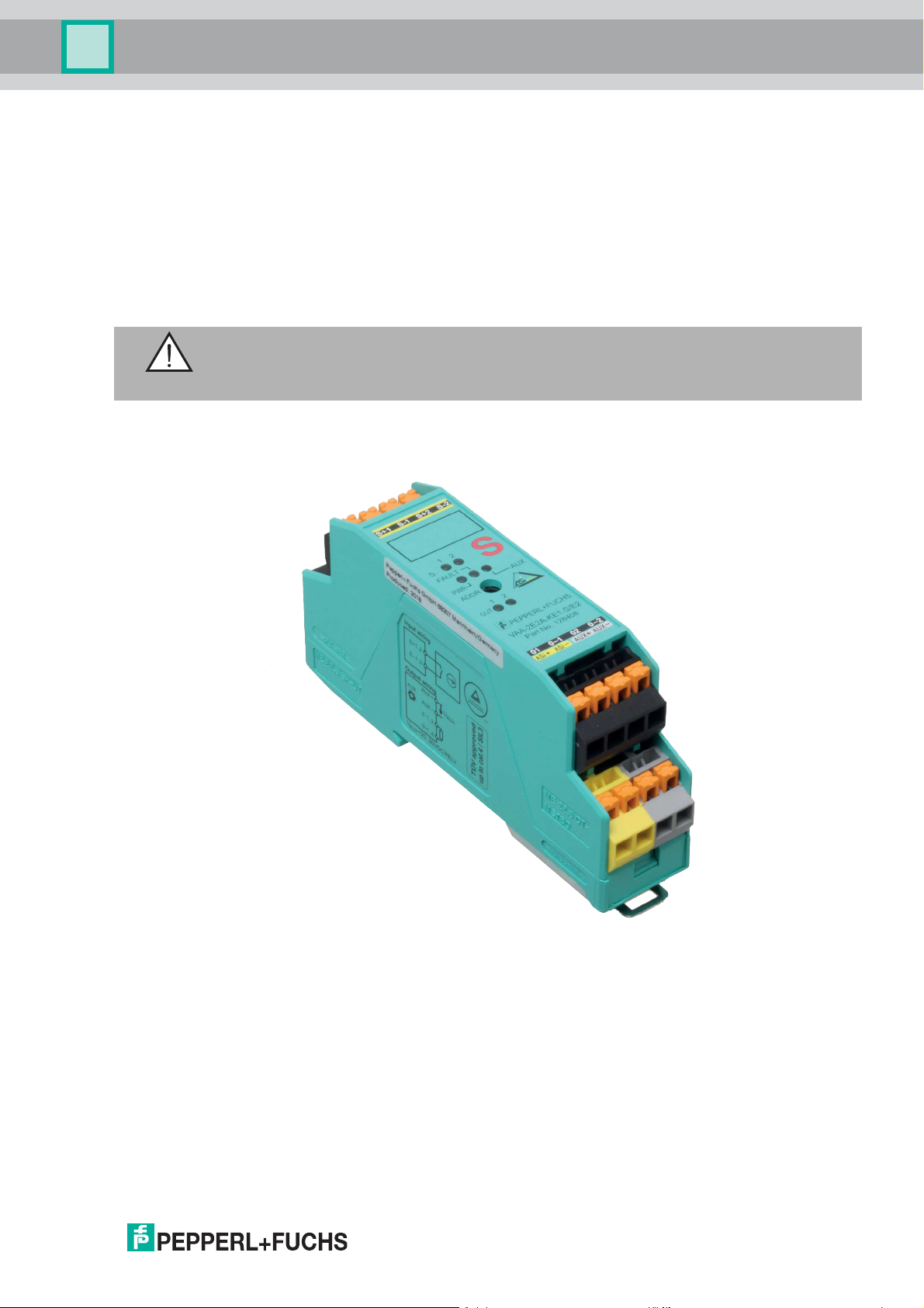
VAA-2E2A-KE1-S/E2,
VAA-2E2A-KE1P-S/E2
Original Operating Instructions
Page 2
VAA-2E2A-KE1-S/E2, VAA-2E2A-KE1P-S/E2
With regard to the supply of products, the current issue of the following document is ap-
plicable: The General Terms of Delivery for Products and Services of the Electrical Indus-
try, published by the Central Association of the Electrical Industry (Zentralverband
Elektrotechnik und Elektroindustrie (ZVEI) e.V.) in its most recent version as well as the
supplementary clause: "Expanded reservation of proprietorship"
Page 3

VAA-2E2A-KE1-S/E2, VAA-2E2A-KE1P-S/E2
1 Introduction................................................................................. 5
1.1 Content of this Document ................................................................... 5
1.2 Manufacturer ........................................................................................ 5
1.3 Target Group, Personnel...................................................................... 5
1.4 Symbols Used ...................................................................................... 6
2 Product Description ................................................................... 7
2.1 Intended Use ........................................................................................ 7
2.1.1 Non-Secure Outputs.......................................................................... 7
2.2 AS-Interface Safety at Work VAA-2E2A-KE1-S/E2 and VAA-2E2A-
KE1P-S/E2............................................................................................. 7
2.3 Peripheral Requirements..................................................................... 8
2.4 Connections and Displays .................................................................. 8
2.5 Interfaces and Connections................................................................ 9
2.5.1 AS-Interface, Auxiliary Energy ........................................................... 9
2.5.2 Inputs............................................................................................... 10
2.5.3 Outputs ............................................................................................ 10
3 Commissioning......................................................................... 12
3.1 Preparation ......................................................................................... 12
3.2 Configuring the AS-Interface Safety Monitor .................................. 12
3.3 Installation .......................................................................................... 12
3.4 Addressing Modules.......................................................................... 12
3.5 Operational Testing............................................................................ 12
3.6 Operating Mode.................................................................................. 13
3.7 Operation ............................................................................................ 13
4 Maintenance and Repair .......................................................... 14
4.1 Maintenance and Repair.................................................................... 14
5 Technical Data........................................................................... 15
3
Page 4
VAA-2E2A-KE1-S/E2, VAA-2E2A-KE1P-S/E2
6 Appendix A................................................................................ 18
6.1 Application Examples ........................................................................ 18
6.2 Category 2...........................................................................................18
6.3 Category 3...........................................................................................18
6.4 Category 4...........................................................................................21
7 Appendix B................................................................................ 24
7.1 Summary of the Requirements for Categories
in Accordance with EN 954-1/ISO 13849-1 ......................................24
7.2 Certificates ..........................................................................................25
7.3 Probability of Failure on Demand Calculation.................................25
7.4 Transfer Time of the Safety-Relevant Information ........................... 25
4
Page 5
VAA-2E2A-KE1-S/E2, VAA-2E2A-KE1P-S/E2
Introduction
1 Introduction
1.1 Content of this Document
This document contains information required to use the product in the relevant phases of the
product life cycle. This may include information on the following:
■
Product identification
■
Delivery, transport, and storage
■
Mounting and installation
■
Commissioning and operation
■
Maintenance and repair
■
Troubleshooting
■
Dismounting
■
Disposal
Note!
For full information on the product, refer to the further documentation on the Internet at
www.pepperl-fuchs.com.
The documentation comprises the following parts:
■
This document
■
Datasheet
In addition, the documentation may comprise the following parts, if applicable:
■
EU-type examination certificate
■
EU declaration of conformity
■
Attestation of conformity
■
Certificates
■
Control drawings
■
Instruction manua l
■
Other documents
1.2 Manufacturer
Pepperl+Fuchs Gm bH
Lilienthalstraße 200, 68307 Mannheim, Germany
Internet: www.pepperl-fuchs.com
1.3 Target Group, Personnel
Responsibility for planning, assembly, commissioning, operation, maintenance, and
dismounting lies with the plant operator.
Only appropriately trained and qualified personnel may carry out mounting, installation,
commissioning, operation, maintenance, and dismounting of the product. The personnel must
have read and understood the instruction manual and the further docum entation.
Prior to using the product make yourself familiar with it. Read the document carefully.
130863 2019-04
5
Page 6

VAA-2E2A-KE1-S/E2, VAA-2E2A-KE1P-S/E2
Introduction
1.4 Symbols Used
This document contains symbols for the identification of warning messages and of informative
messages.
Warning Messages
You will find warning messages, whenever dangers may arise from your actions. It is mandatory
that you observe these warning messages for your personal safety and in order to avoid
property damage.
Depending on the risk level, the warning messages are displayed in descending order as
follows:
Danger!
This symbol indicates an imminent danger.
Non-observance will result in personal injury or death.
Warning!
This symbol indicates a possible fault or danger.
Non-observance may cause personal injury or serious property damage.
Caution!
This symbol indicates a possible fault.
Non-observance could interrupt the device and any connected systems and plants, or result in
their complete failure.
Informative Symbols
Note!
This symbol brings important information to your attention.
Action
This symbol indicates a paragraph with instructions. You are prompted to per form an action or
a sequence of actions.
130863 2019-04
6
Page 7
VAA-2E2A-KE1-S/E2, VAA-2E2A-KE1P-S/E2
Product Description
2 Product Description
2.1 Intended Use
When used as intended, the AS-Interface safety module allows the operation of sensorcontrolled personal protective equipment up to category 4 and PL e as per ISO 13849 or up to
SIL 3 as per EN/IEC 61508 and EN/IEC 62061 in combination with an appropriately
programmed AS-Interface safety monitor. The safety level of the application is determined
either via a risk analysis, e.g., in accordance with EN 1050, or is taken from a C standard.
2.1.1 Non-secure outputs
Warning!
The outpu ts must not be used for safety-related functions.
2.2 AS-Interface Safety at Work VAA-2E2A-KE1-S/E2 and VAA-2E2A-KE1PS/E2
The VAA-2E2A-KE1*-S/E2 is an AS-Interface safety module with two safety-related inputs and
two outputs. A du al-channel mechanical switch can be connected to the two safety-related
inputs, or a single-channel mechanical switch can be connected to each input. The outputs are
conventional electronic outputs that can have a total load of 1 A (m ax 0.5 A per output). The
housing is only 22.5 mm wide and 48.5 mm tall and takes up little space in the switch cabinet.
The module is mounted by snapping it onto the 35 mm DIN rail in compliance with EN 50022.
An addressing socket is integrated into the module.
The connection is made via plug-in terminals. A four-way (black) terminal block is used for the
inputs. The AS-Interface is connected via a two-way (yellow) terminal block. Each channel has
an LED mounted on the top side of the module to display the current switching status. There is
an LED for monitoring AS-Interface communication and for displaying that the module has the
address 0.
130863 2019-04
7
Page 8
VAA-2E2A-KE1-S/E2, VAA-2E2A-KE1P-S/E2
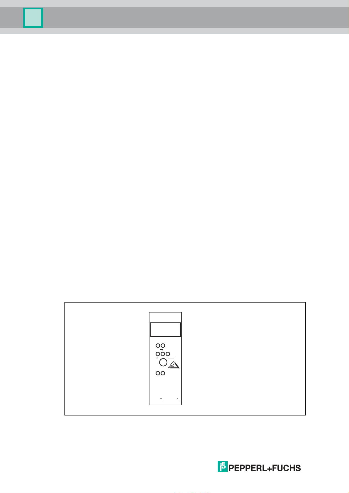
+ +
1
122
S
FAULT
AUX
PWR
ADDR
OUT
01
AS-i AS-i
0 1
02
AUX AUX
0 2
S
S+1 S-1 S+2 S-2
Product Description
If single-channel force-guided mechanical switches are connected, the module can be
upgraded to Performance Level c in accordance with EN ISO 13849-1 if wired appropriately
and if the switch is selected accordingly. If a dual-channel force-guided mechanical switch is
connected, the module can be upgraded to Performance Level e in accordance with
EN ISO 13849-1 if wired appropriately and if the switch is selected accordingly. As per the
approval in accordance with IEC 61508 and IEC 62061, a Safety Integrity Level of up to SIL 3
can be reached. Both module inputs are occupied. The two channels belonging to the
mechanical switch are monitored for crossed circuits. Each LED displays the voltage of the ASInterface and the external power supply.
2.3 Peripheral Requirements
Safety Monitor Requirements
The module must only be used as a safety-related slave in an AS-Interface segment with the
corresponding AS-Inter face safety monitor as intended. The AS-Interface safety monitor must
meet the requirements of the "Specification of Safe AS-Interface Transmission" system
specification (version 2.01) dated 05/12/2000.
To evaluate a safety-related function in accordance with a safety standard, all components
found in the function must be evaluated in accordance with this standard.
The wiring and programming of the safety monitor determine whether or not the required safety
function performs correctly. This also applies to the required safety response after a code fault
or failure (see also safety monitor documentation). The safety function (including all safetyrelated sensors) must be checked prior to initial commissioning. The safety monitor PL
category or SIL mu st, as a minimum, comply with the PL category or SIL required by the
application.
Cabling Requirements
The requirements set out in EN/IEC 60204-1 or similar must always be observed. The
requirements for the external cabling and selection of connected sensors are based both on
the level of functionality to be achieved, and on the required category (ISO 13849-1, EN/IEC
61508, or EN/IEC 62061).
Switches or Mechanical Contacts
The switches m ust be positive opening. Combinations of switches that provide an equivalent
level of safety (fault behavior analysis) can be used.
2.4 Connections and Displays
Figure 2.1
130863 2019-04
8
Page 9

VAA-2E2A-KE1-S/E2, VAA-2E2A-KE1P-S/E2
Product Description
Safety related inputs
Designation Description
S1+ Mechanical switch 1+
S1- Mechanical switch 1-
S2+ Mechanical switch 2+
S2- Mechanical switch 2-
Outputs
Designation Description
O1 Output 1+
O-1 Output 1-
O2 Output 2+
O-2 Output 2-
Supply
Designation Description
ASi+ AS-Interface +
ASi- AS-Interface -
AUX+ Auxiliary power U
AUX- Auxiliary power U
Aux
Aux
+
-
Displays
Designation Description
LED FAULT Error display; LED red
red: communication error or address is 0
red flashing: Output supply overload
LED PWR AS-Interface voltage; LED green
LED AUX Ext. auxiliary voltage U
LED IN Switching state (input); 2 LED yellow
LED OUT Switching state (output); 2 LED yellow
2.5 Interfaces and Connections
2.5.1 AS-Interface, Auxiliary energy
In case of the KE1-series all interfaces are connected via removable terminals. Thus also ASInterface and auxiliary energy. The cable has to meet the minimum requirements for ASInterface (e.g. AS-Interface flat band cable, VAZ-FK-S-YE for AS-Interface and VAZ-FK-S-BK
for auxiliar y energy).
; LED green
AUX
130863 2019-04
9
Page 10

VAA-2E2A-KE1-S/E2, VAA-2E2A-KE1P-S/E2
1 2
Short circuit jumper
1
2
Product Description
2.5.2 Inputs
General
The switches are connected to removable terminals. One or more mechanical switches can be
connected in series per channel.
Figure 2.2 = 2 mechanical switches (or one two-channel switch)
If only one single-channel switch is to be used, input 1 should be u sed in this case. If input 2 is
not connected, it must be bridged.
Safety Category
The module contains two independent and redundant input channels that individually meet the
requirements of category 4 in accordance with ISO 13849-1.
Crossed Circuit Monitoring
The inputs are m onitored for inter-crossed circuits. The crossed circuit monitoring function is
able to detect low-resistance crossed circuits between the two inputs caused by a metallic
connection.
2.5.3 Outputs
The outputs are designed according to the AS-Interface standard. These are switched to
positive potential (PNP technology).
The outputs can be operated in two modes:
= 1 me chanical switch
1. The outputs are controlled directly by the corresponding data bits of the AS-Interface master.
2. The output signals of the AS-Interface master are linked with the secure inputs. The outputs are turned on if the master turns them on or if the inputs are in a secure state.
This operating mode is used to control signal lights that must display the state of the inputs
without the master being involved.
130863 2019-04
10
Page 11

VAA-2E2A-KE1-S/E2, VAA-2E2A-KE1P-S/E2
U
24 V
PELV
AUX
OUT1
S1
AS-Interface
+
-
AS-i Chip
≥ 1
P0
DO0
Product Description
Figure 2.3 Output modes
Modes and logic table of the outputs
The modes are selected by the Master with parameter bit P0:
P0 S1 S2
1)
DO0 DO1
2)
OUT1 OUT2 Mode
1 X X 0 0 0 0 Outputs independend of inputs
X X 1 1 1 1
0 0 0 X X 1 1 Open switch at the input sets
the corresponding output
1 1 0 0 0 0 When the switches are closed
1 1 1 1 1 1
1)
0 = an open switch (secure state).
on the input, the master
controls the output
1 = closed switch.
X = any state that has no effect on the outputs.
2)
1 = outputs are turned on.
0 = outputs are voltage-free.
130863 2019-04
11
Page 12

VAA-2E2A-KE1-S/E2, VAA-2E2A-KE1P-S/E2
Commissioning
3 Commissioning
3.1 Preparation
Unpacking the device
1. Check the packaging and contents for damage.
In the event of damage, inform the shipping company and notify the supplier.
2. Check the package contents against your order and the shipping documents for
completeness and accuracy.
Should you have any questions, direct them to Pepperl+Fuchs.
3. Retain the original packaging in case the device is to be stored or shipped again at a later
date.
3.2 Configuring the AS-Interface Safety Monitor
For details of necessary organizational measures affecting configuration of the safety monitor,
please refer to the documentation for the safety monitor.
Safety Classification
The module contains two independent, redundant input channels. If both input channels are
used, the module is suitable for use up to category 4/PL e in accordance with ISO 13849-1, or
SIL 3 in accordance with EN/IEC 61508 and EN/IEC 62061. In this case, the monitor must be
programmed so that dual-channel switching is monitored.
If a single-channel switch is used, the module is suitable for use up to category 2/PL c in
accordance with ISO 13849-1, or SIL 1 in accordance with EN /IEC 61508 and EN/IEC 62061.
Only tested and certified power supplies with safe isolation may be used to supply power.
These power supplies m ust have PELV voltage in accordance with EN 50295/IEC 62026-2,
and a minimum MTBF of 50 years. The power supplies are designed to exclude a short circuit
between the primary and secondary sides.
3.3 Installation
For installation of the module a suitable top hat DIN rail in accordance with DIN 50022 is
recommended.
3.4 Addressing modules
Addressing of the module is performed by means of a manual addressing device or with an ASInterface master. If a manual addressing device is used, it should be connected and addressed
to the addressing socket of the module (identified with ADDR) using the addressing cable
included with delivery. Addresses from 1 to 31 can be assigned. The state as supplied is
address 0.
3.5 Operational Testing
12
Perform function tests as part of the installation by activating the safety function. The
operational test uncovers all existing faults at the time of installation. Because the safe inputs
are monitored for crossed circuits, it is not necessary to test for short circuits in the cabling.
Note!
In the case of single-channel safety functions, test the function for each channel.
For applications of category 4/PL e in accordance with ISO 13849-1 or SIL 3 in accordance
with EN/IEC 61508 and EN/IEC 62061, the two inputs must be monitored using the safety
monitor to ensure that they are synchronous.
130863 2019-04
Page 13

VAA-2E2A-KE1-S/E2, VAA-2E2A-KE1P-S/E2
Commissioning
Performing a Function Test
1. Activate the safety function by interrupting the inpu t. This can be done by actuating a connected m echanical switch or on the cable.
2. Check whether the safety monitor detects the interruption without issuing a fault message.
3. Stop the interruption on the input on the connected mechanical switch or on the cable.
4. Enable the input on the safety m onitor.
3.6 Operating Mode
Activating operating modes for the inputs is not possible.
The parameters in the AS interface may influence the performance of the outputs. The chapter
"Operating principle" contains a more accurate description.
3.7 Operation
Programming the safety monitor parameters defines the safety function of the device. Read the
corresponding documentation.
130863 2019-04
13
Page 14

VAA-2E2A-KE1-S/E2, VAA-2E2A-KE1P-S/E2
Maintenance and Repair
4 Maintenance and Repair
4.1 Maintenance and repair
Regular function tests may be necessary, depending on the safety category.
14
130863 2019-04
Page 15

VAA-2E2A-KE1-S/E2, VAA-2E2A-KE1P-S/E2
99.6
48.5
50.5
22.5
Technical Data
5 Technical Data
Figure 5.1
General Data
Slave type Safety slave
UL file number E223772
Functional Safety Data
Safety Integrity Level (SIL) SIL 3
Performance Level (PL) PL e
MTTF
PFH
d
d
200 a
0
PFD 0
Indicators/Operating Elements
FAULT LED Fault indication; LED red
Red: communication fault or address is 0
Red, flashing: output voltage overload
PWR LED AS-Interface voltage; green LED
AUX LED Ext. auxiliary voltage U
; green LED
AUX
IN LED Switching state (input); 2 yellow LEDs
OUT LED Switch state (output); 2 yellow LEDs
Electrical Data
Auxiliary power (output) 20 VDC ... 30 VDC PELV
Rated operating voltage 26.5 V ... 31.6 V from AS-Interface
Rated operating current ≤ 70 mA
Protection class III
Surge protection U
, Ue: Overvoltage category II, securely isolated power
AUX
supplies (PELV)
130863 2019-04
15
Page 16

VAA-2E2A-KE1-S/E2, VAA-2E2A-KE1P-S/E2
Technical Data
Input
Number/type 2 safety-related inputs for mechanical contacts, monitored for
crossed circuits:
2 single-channel contacts: up to category 2/PL c in accordance
with ISO 13849-1 or
1 dual-channel contact: up to category 4/PL e in accordance with
ISO 13849-1
Cable length must not exceed 300 m per input.
Power supply From AS-Interface
Voltage 20 VDC ... 30 VDC, pulsed
Current rating Input current limited ≤ 15 mA,
overload and short-circuit proof
Output
Number/type 2 conventional electronic outputs, PNP
Power supply From external auxiliary voltage U
Current 0.5 A per output
Voltage ≥ (U
AUX
- 0.5 V)
AUX
Programming Instructions
Profile S-7.B
IO code 7
ID code B
ID1 code F
ID2 code 0
Data bit (function via ASInterface)
D0 Dyn. security code 1 OUT 1
D1 Dyn. security code 1 OUT 2
D2 Dyn. security code 2 -
D3 Dyn. security code 2 -
Parameter bit (programmable
via AS-Interface)
P0 Output link:
P1 Not used
P2 Not used
P3 Not used
Input Output
Function
P0 = 1 (default setting): The outputs are controlled via the ASInterface.
P0 = 0: The outputs are controlled via the AS-Interface or the
inputs. When the contact of an input is opened, the
corresponding output is activated.
16
Directive Conformity
Electromagnetic compatibility
Directive 2014/30/EU EN 62026-2:2013 EN 61496-1:2004
130863 2019-04
Page 17

VAA-2E2A-KE1-S/E2, VAA-2E2A-KE1P-S/E2
Technical Data
Standard Conformity
Insulation coordination EN 50178:1998
Electromagnetic
compatibility
Degree of protection EN 60529:2000
Fieldbus standard EN 62026-2:2013
Electrical safety EN 50178:1998 IEC 60204-1:2007
Emitted interference EN 61000-6-4:2007
AS-Interface EN 62026-2:2013
Functional safety EN ISO 13849-1:2015 up to PL e, IEC 61508:2010 and
Standards NFPA 79:2002
Ambient Conditions
Ambient temperature -25 °C ... 50 °C (-13 °F ... 122 °F)
Storage temperature -25 °C ... 85 °C (-13 °F ... 185 °F)
Relative humidity 85 %, non-condensing
Climatic conditions For indoor use only
Operating altitude ≤ 2000 m ASL
Shock and impact
resistance
Vibration resistance 0.75 m m 10 Hz ... 57 Hz, 5 g 57 Hz ... 150 Hz, 20 cycles
Degree of pollution 2
EN 61000-6-2:2005, EN 61000-4-5:2005 1 kV asymmetrical,
criterion B, EN 61000-6-4:2007
IEC 62061:2005/A2:2015 up to SIL 3
10 g, 16 ms in 6 spatial directions, 1000 shocks
Mechanical Data
Degree of protection IP20
Connection
Material
Housing PA 66-FR
Mass 80 g
Mounting DIN m ounting rail
Clamping screw tightening
torque
Removable terminals, terminal connection ≤ 2.5 mm
0.5 Nm ... 0.6 Nm
2
130863 2019-04
17
Page 18

VAA-2E2A-KE1-S/E2, VAA-2E2A-KE1P-S/E2
Channel 1
Channel 2
Module
S+1
S-1
S+2
S-2
Channel 1
Channel 2
Module
S+1
S-1
S+2
S-2
Appendix A
6 Appendix A
6.1 Application Examples
Note!
The examples listed here correspond to our understanding of the categories in accordance
with ISO 13849-1 and should not be regarded as binding.
6.2 Category 2
The safety function(s) must be tested at appropriate intervals of time by the machine control
system. Loss of the safety function will be detected by the test. The test intervals must be
adjusted to match the application.
Connecting two independent mechanical position switches of Category 2:
Figure 6.1
6.3 Category 3
The occurrence of a fault must not lead to the loss of the safety function.
Connection of two dependent mechanical position switches per channel (two safety functions).
Example 1:
Figure 6.2
18
130863 2019-04
Page 19

VAA-2E2A-KE1-S/E2, VAA-2E2A-KE1P-S/E2
Channel 1
Channel 2
Module
S+1
S-1
S+2
S-2
S+1
S-1
S+2
S-2
Safety circuit
Module
separately
laid
separately
laid
Appendix A
Example 2:
If a dangerous failure (short circuit) of the switches cannot be excluded, these switches must
be duplicated and connected in series.
Figure 6.3
Example 3:
If a short circuit in the cabling across the switches cannot be excluded, both channels are
needed to achieve a category 3 safety fu nction.
Figure 6.4
The following function blocks can be parameterized to achieve sa fety category 3 in this
application during operation of the AS-Interface safety module on a safety monitor (e.g., VAS1A-K12 or VAS-2A-K12):
130863 2019-04
Examples 1 and 2:
Dual-channel, independent
19
Page 20

VAA-2E2A-KE1-S/E2, VAA-2E2A-KE1P-S/E2
Safety circuit
Module
S+1
S-1
S+2
S-2
Appendix A
Example 3:
Dual-channel, dependent
Dual-channel, force-guided
Danger!
The function block "Dual-channel, independent" must not be used in example 3.
6.4 Category 4
The occurrence of a fault and an accumulation of faults must not lead to the loss of the safety
function.
Example 1:
Connection of a dual-channel mechanical position switch.
To detect a dangerous accumulation of faults, the safety function must be tested. The test
intervals must be adapted to the application.
Figure 6.5
20
130863 2019-04
Page 21

VAA-2E2A-KE1-S/E2, VAA-2E2A-KE1P-S/E2
S+1
S-1
S+2
S-2
Safety circuit
Module
separately
laid
separately
laid
Appendix A
Example 2:
If a dangerous failure (short circuit) of the switch cannot be excluded, two dependent
mechanical switches must be used for each channel. To detect a dangerous accum ulation of
faults, the safety function must be tested. The test intervals must be adapted to the application.
Figure 6.6
The following function blocks can be parameterized to achieve sa fety category 4 in this
application during operation of the AS-Interface safety module on a safety monitor (e.g., VAS1A-K12 or VAS-2A-K12):
Dual-channel, dependent
Dual-channel, force-guided
Danger!
The function block "Dual-channel, independent" must not be used.
130863 2019-04
Warning!
The cable length between the module and the sensor is limited to 300 m .
21
Page 22

VAA-2E2A-KE1-S/E2, VAA-2E2A-KE1P-S/E2
Appendix B
7 Appendix B
7.1 Summary of the Requirements for Categories in Accordance with EN 954-1/ISO 13849-1
Essential
principle to
achieve
safety
Via the
selection of
components
Category Summary of the requirement System behavior
B The safety-related parts of machine
control and/or their components must
be designed, constructed, selected,
assembled, and combined in
accordance with the applicable
standards such that they can
withstand the expected influences.
1 The requ irements of B must be
fulfilled.
Use of components and principles
that are proven for safety engineering
purposes.
If a fault occurs, it can lead
to the loss of the safety
function.
As described for category B,
but with the safety function
providing a higher level of
safety-related reliability.
1)
24
130863 2019-04
Page 23

VAA-2E2A-KE1-S/E2, VAA-2E2A-KE1P-S/E2
Appendix B
Category Summary of the requirement System behavior
2 The requirements of B must be
fulfilled and principles that are proven
for safety engineering purposes must
be used.
The safety function(s) must be
checked by the machine control at
suitable intervals.
NOTE: What is suitable depends on
the application and the type of
machine.
3 The requirements of B must be
fulfilled and principles that are proven
for safety engineering purposes must
be used.
The control systems must be
designed such that:
■
An individual fault in the control
system does not lead to the loss
of the safety function, and
■
Whenever reasonably
practicable, individual faults are
detected.
4 The requirements of B must be
fulfilled and principles that are proven
for safety engineering purposes must
be used.
The control systems must be
designed such that:
■
An individual fault in the control
system does not lead to the loss
of the safety function, and
1)
■
The occurrence of a fault
can lead to the loss of
the safety function
between the test
intervals.
■
The loss of the safety
function is detected by
the test.
■
When an individual fault
occurs, the safety
function is always
maintained.
■
Some, but not all, faults
are detected.
■
An accumulation of
undetected faults can
lead to the loss of the
safety function.
When faults occur, the
safety function is always
maintained.
The faults are detected in
good time to prevent a loss
of the safety fu nctions.
Essential
principle to
achieve
safety
Via the
structure
■
The individual fault is detected
during or before the next time the
safety function is invoked. If this is
not possible, then an
accumulation of faults must not
lead to the loss of the safety
function.
1)
The risk assessment indicates whether the complete or partial loss of the safety
function(s) due to the occurrence of faults is acceptable.
130863 2019-04
25
Page 24

VAA-2E2A-KE1-S/E2, VAA-2E2A-KE1P-S/E2
Appendix B
7.2 Certificates
Approvals in accordance with EN/IEC 61508 and EN/IEC 62061.
7.3 Probability of Failure on Demand Calculation
To calculate the probability of dangerous failure on demand (PFD) of a safety-related function,
the PFD values for all components used within this function must be taken into consideration. In
the case of dual-channel applications, the AS-Interface safe input module does not significantly
contribute to the PFD or PFH (probability of dangerous failure per hour) of the overall system.
The PFD and PFH values for single-channel application can be found in the data sheet. The
PFD or PFH values of the other components, in particular the safety monitor, can be found in
the relevant documentation.
7.4 Transfer time of the safety-relevant information
The transfer time depends essentially on the monitor. The corresponding documentation and
the switch-off times of the actuators must be observed.
26
130863 2019-04
Page 25

FACTORY AUTOMATION –
SENSING YOUR NEEDS
Worldwide Headquarters
Pepperl+Fuchs GmbH
68307 Mannheim · Germany
Tel. +49 621 776-0
E-mail: info@de.pepperl-fuchs.com
USA Headquarters
Pepperl+Fuchs Inc.
Twinsburg, Ohio 44087 · USA
Tel. +1 330 4253555
E-mail: sales@us.pepperl-fuchs.com
Asia Pacific Headquarters
Pepperl+Fuchs Pte Ltd.
Company Registration No. 199003130E
Singapore 139942
Tel. +65 67799091
E-mail: sales@sg.pepperl-fuchs.com
www.pepperl-fuchs.com
Subject to modifications
Copyright PEPPERL+FUCHS • Printed in Germany
130863 / DOCT-0168E
04/2019
 Loading...