


Splice sensor UGB-18GM50-255-2E3-150MM-V15-Y
Technical data
General specifications
Sensing range 20 ... 60 mm , optimal distance: 45 mm
Transducer frequency 255 kHz
Indicators/operating means
LED green Display: readiness
LED yellow Display: splice detected
LED red Indication: No sheet detected (Air)
Electrical specifications
Model Number
UGB-18GM50-255-2E3-150MM-V15-Y
Features
• Ultrasonic system for splice
detection
• Insensitive to printing, colors, and
shining surfaces
• Very high processing speeds are
possible.
• Short version
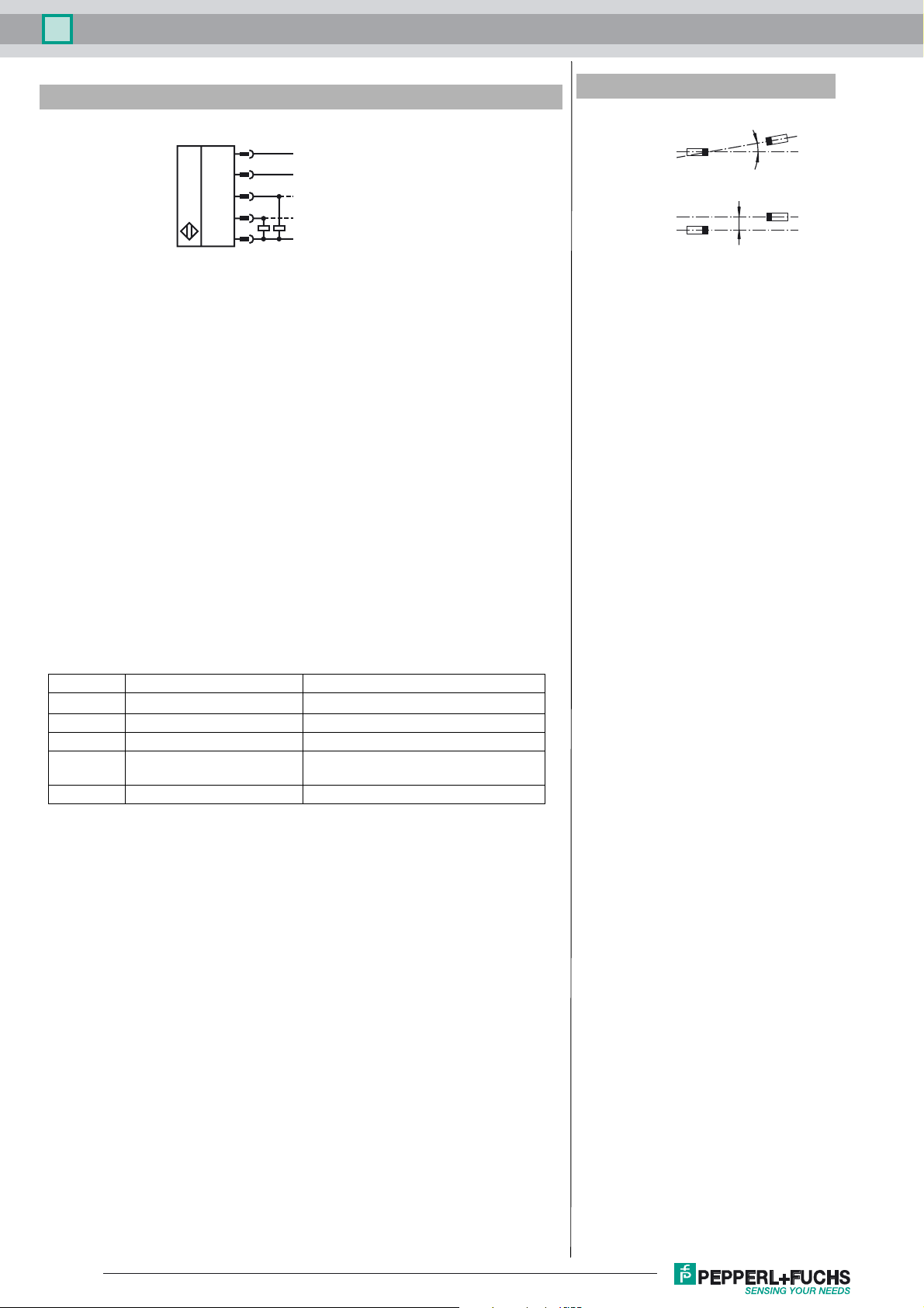
Diagrams
Mounting/Adjustment
Suggestions:
a = 5 mm ... 15 mm
b > 10 mm
d = 40 mm ... 45 mm
β = 20˚ ... 40˚
b
Operating voltage U
No-load supply current I
Time delay before availability t
Input
Input type Teach-In input
Pulse length ≥ 500 ms
Impedance ≥ 10 kΩ
Output
Output type 2 switch outputs PNP, NC
Rated operating current I
Voltage drop U
Switch-on delay t
Switch-off delay t
Pulse extension ≥ 120 ms programmable
Ambient conditions
Ambient temperature 0 ... 60 °C (32 ... 140 °F)
Storage temperature -40 ... 70 °C (-40 ... 158 °F)
Mechanical specifications
Connection type Cable connector M12 x 1 , 5-pin with PVC Cable, 150 mm
Degree of protection IP67
Material
Housing nickel plated brass; plastic components: PBT
Transducer
Mass 150 g
Cable length l1 = 0.3 m
Compliance with standards and
directives
Standard conformity
St
andard
Approvals and certificates
UL approval cULus Listed, General Purpose
CSA approval cCSAus Listed, General Purpose
CCC approval CCC approval / marking not required for products rated ≤36 V
B
0
v
e
d
on
off
s EN
Dimensions
18 ... 30 V DC , ripple 10 %
< 60 mA
< 500 ms
0-level: -U
1-level: +U
2 x 100 mA , short-circuit/overload protected
≤ 3 V
≤ 600 µs
≤ 600 µs
poxy resin/hollow glass sphere mixture; polyurethane foam
e
l2 = 0.15 m
IEC
... -UB + 1V
B
- 1 V ... +U
B
60947-5-2:2007+A1:20
60947-5-2:2007 + A1:2012
SS
B
12
β
a
Release date: 2017-09-25 08:48 Date of issue: 2017-09-25 281037_eng.xml
Refer to “General Notes Relating to Pepperl+Fuchs Product Information”.
d
l1
Emitter unit
24
Evaluation unit with
receiver unit
LEDs
22
12
M18 x 1
M18 x 1
24
30
50
53
l2
1
Splice sensor UGB-18GM50-255-2E3-150MM-V15-Y
Electrical Connection
1
5
4
U
2
3
Operation in applications with increased ESD requirements
Using the included metal screw caps, the sensor can be used in applications with increased
ESD requirements up to 30 kV (ESD = electrostatic discharge). The metal coupling nuts are
screwed on the front of the transmitter and receiver. The installation of the transmitter and receiver must ensure a large area electrical connection to the machine earth.
+UB
Teach-In
Output splice
Output air
-UB
Description of sensor functions
The ultrasonic double sheet monitor for splice detection can be used in all applications,
where an automatic detection of glue dots, splices, bondings or the absence of base material is required, to protect machines or to evade waste production. The double-sheet
monitor is based on the ultrasonic through-beam principle. The following can be detected:
- No base material, i.e. air,
- glue dots, splices, bondings
A microprocessor system evaluates the signals. The appropriate switch outputs are set
as a result of the evaluation. Changes in ambient conditions such as temperature and
humidity are compensated for automatically. The interface electronics is integrated into
a compact M18 metal housing together with a sensor head.
Additional Information
Angular misalignment
< +/- 1°
α
Sensor offset
s < +/- 1 mm
α
s
Electrical connection
The sensor is equipped with with a 5 pin connector. The functionality of the connections
is described in the following table. The teach input (pin 5) is used to teach the sensor.
Pin Switching on Comments
1+U
4 Switch output for splices Pulse width corresponds to the event
2 Switch output for air Pulse width corresponds to the event
5-U
3-UB
B
/ n.c. / +U
B
B
Normal operation / output pulse prolongation / TEACH-IN
Normal mode
The sensor is working in normal mode if the function input (pin 5) is applied to -UB or not
connected.
Displays:
LED yellow: Detection of splices
LED green: Power on
LED red: Detection of air (no base material)
Switch outputs:
The switch outputs are only active in normal operation!
pin 4: Splice output
pin 2: Air output
Output pulse extension
If the teach input (pin 5) is not connected, when switching on the power supply, the sensor operates with output pulse prolongation. Events, shorter than 120 ms cause an output
pulse duration of 120 ms at the Splice output. For sensor operation without pulse prolongation, the teach input (pin 5) has to be connected with
ched on.
Please note:
This can result in a condition in which more than one switch output is switched through!
-U
while power supply is swit-
B
Release date: 2017-09-25 08:48 Date of issue: 2017-09-25 281037_eng.xml
Refer to “General Notes Relating to Pepperl+Fuchs Product Information”.
2

Splice sensor UGB-18GM50-255-2E3-150MM-V15-Y
TEACH-IN mode
Connecting the teach input (pin 5) with +UB for at least 500 ms causes the sensor to change into TEACH-IN mode. The TEACH-IN
procedure has to be carried out with base material. In case of inhomogeneous base materials we suggest to teach the sensor with
activated material feeding and a corresponding prolongation of the TEACH-IN procedure.
During the TEACH-IN procedure flashes the yellow LED; the green LED is off.
After returning to the normal operation mode (teach input (pin 5) detached from
cedure was successful or not.
TEACH-IN procedure successful: green LED flashes 3 times
TEACH-IN procedure not successful: red LED flashes 3 times
Notes:
If two or more double sheet controls are used in the immediate vicinity of each other, there may be mutual interference between them,
which can result in improper functionality of the devices. Mutual interference can be prevented by introducing suitable countermeasures
when planning systems. Suitable measures can be:
- Mounting of sound absorbers (foam material)
- mounting of sound separators (sheet metal)
- insallation of the sensors with different directions of sound transmission.
+U
) the sensor indicates whether the TEACH-IN pro-
B
Release date: 2017-09-25 08:48 Date of issue: 2017-09-25 281037_eng.xml
Refer to “General Notes Relating to Pepperl+Fuchs Product Information”.
3
 Loading...