

Splice sensor UGB-18GM50-255-2E3
Technical data
General specifications
Sensing range 20 ... 60 mm , optimal distance: 45 mm
Transducer frequency 255 kHz
Indicators/operating means
LED green Display: readiness
LED yellow Display: splice detected
LED red Indication: No sheet detected (Air)
Electrical specifications
Model Number
UGB-18GM50-255-2E3
Features
• Ultrasonic system for splice
detection
• Short version
• Insensitive to printing, colors, and
shining surfaces
• Very high processing speeds are
possible.
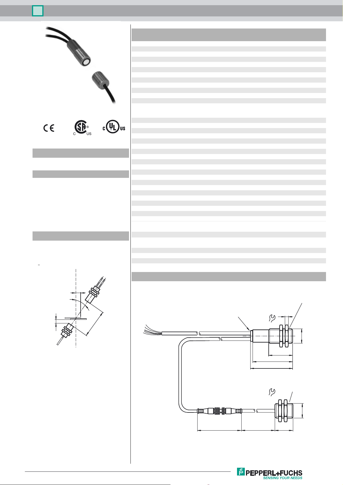
Diagrams
Mounting/Adjustment
Suggestions:
a = 5 mm ... 15 mm
b > 10 mm
d = 40 mm ... 45 mm
β = 20˚ ... 40˚
Operating voltage U
No-load supply current I
Time delay before availability t
Input
Input type Teach-In input
Pulse length ≥ 500 ms
Impedance ≥ 10 kΩ
Output
Output type 2 switch outputs PNP, NC
Rated operating current I
Voltage drop U
Switch-on delay t
Switch-off delay t
Pulse extension ≥ 120 ms programmable
Ambient conditions
Ambient temperature 0 ... 60 °C (32 ... 140 °F)
Storage temperature -40 ... 70 °C (-40 ... 158 °F)
Mechanical specifications
Connection type cable PVC , 2 m
Core cross-section 0.14 mm
Degree of protection IP67
Material
Housing nickel plated brass; plastic components: PBT
Transducer epoxy resin/hollow glass sphere mixture; polyurethane foam
Mass 150 g
Compliance with standards and
directives
Standard conformity
Standards EN 60947-5-2:2007 + A1:2012
Approvals and certificates
UL approval cULus Listed, General Purpose
CSA approval cCSAus Listed, General Purpose
CCC approval CCC approval / marking not required for products rated ≤36 V
B
0
v
e
d
on
off
Dimensions
18 ... 30 V DC , ripple 10 %
< 60 mA
< 500 ms
0-level: -U
1-level: +U
2 x 100 mA , short-circuit/overload protected
≤ 3 V
≤ 600 µs
≤ 600 µs
IEC 60947-5-2:2007 + A1:2012
... -UB + 1V
B
- 1 V ... +U
B
2
SS
B
b
β
wires 70 mm with
a
d
wire end ferrules
l = 2 m
l = 0.5 m
LEDs
53
Evaluation unit with
receiver unit
4
24
M18 x 1
30
50
Emitter unit
24
ø 15
M18 x 1
70
500
22
Release date: 2016-04-25 09:44 Date of issue: 2016-04-25 193008_eng.xml
Refer to “General Notes Relating to Pepperl+Fuchs Product Information”.
1
Splice sensor UGB-18GM50-255-2E3
Electrical Connection
Standard symbol/Connection:
Splice control
(BN)
(PK)
(WH)
(BK)
U
(GY)
(BU)
+U
B
TEACH IN
Output splice
Output air
n.c.
-U
B
Accessories
MH-UDB01
Mounting bracket for double sheet monitor
Operation in applications with increased ESD requirements
Using the included metal screw caps, the sensor can be used in applications with increased
ESD requirements up to 30 kV (ESD = electrostatic discharge). The metal coupling nuts are
screwed on the front of the transmitter and receiver. The installation of the transmitter and receiver must ensure a large area electrical connection to the machine earth.
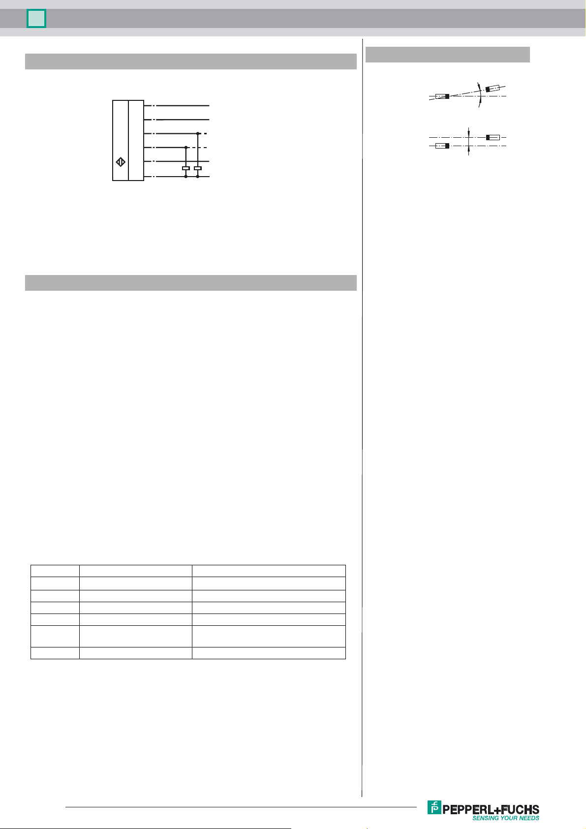
Additional Information
Angular misalignment
a < +/- 1°
Sensor offset
s < +/- 1 mm
a
s
Description of sensor functions
The ultrasonic double sheet monitor for splice detection can be used in all applications,
where an automatic detection of glue dots, splices, bondings or the absence of base material is required, to protect machines or to evade waste production. The double-sheet
monitor is based on the ultrasonic through-beam principle. The following can be detected:
- No base material, i.e. air,
- glue dots, splices, bondings
A microprocessor system evaluates the signals. The appropriate switch outputs are set
as a result of the evaluation. Changes in ambient conditions such as temperature and
humidity are compensated for automatically. The interface electronics is integrated into
a compact M18 metal housing together with a sensor head.
Electrical connection
The sensor is equipped with 6 connecting wires. The functionality of the connections is
described in the following table. The teach input (PK) is used to teach the sensor.
Colour Switching on Comments
BN +U
WH Switch output for splices Pulse width corresponds to the event
BK Switch output for air Pulse width corresponds to the event
GY not connected
PK -U
BU -UB
B
/ n.c. / +U
B
B
Normal operation / output pulse prolongation / TEACH-IN
Normal mode
The sensor is working in normal mode if the function input (PK) is applied to -UB or not
connected.
Displays:
LED yellow: Detection of splices
LED green: Power on
LED red: Detection of air (no base material)
Switch outputs:
The switch outputs are only active in normal operation!
White: WH Splice output
Black: BK Air output
Refer to “General Notes Relating to Pepperl+Fuchs Product Information”.
2
Release date: 2016-04-25 09:44 Date of issue: 2016-04-25 193008_eng.xml
 Loading...