

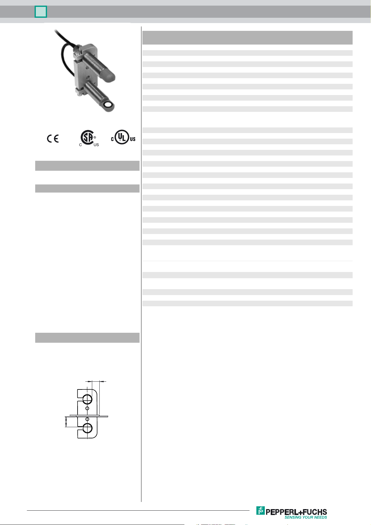
Double sheet sensor UDC-18GMA-400-3E3
Technical data
General specifications
Sensing range 20 ... 60 mm , optimal distance: 45 mm
Transducer frequency 395 kHz
Indicators/operating means
LED green indication: single sheet detected
LED yellow Indication: No sheet detected (Air)
LED red indication: double sheet detected
Electrical specifications
Model Number
UDC-18GMA-400-3E3
Features
• Ultrasonic system for reliable
detection of no, one, or two
overlapping sheet materials,
preferably papers
• No TEACH-IN required
• Function indicators visible from all
directions
• Insensitive to printing, colors, and
shining surfaces
2
• Material weight from 10 g/m
over 2000 g/m
2
• Very wide material spectrum,
finest papers up to thin sheet
metals as well as plastic- and
metal foils
• Perpendicular or inclined sensor
mounting relative to the sheet
plane possible
• Programmable
up to
Operating voltage U
No-load supply current I
Time delay before availability t
Input
Input type Function input
Pulse length ≥ 100 ms
Impedance ≥ 4 kΩ
Output
Output type 3 switch outputs PNP, NC
Rated operating current I
Voltage drop U
Switch-on delay t
Switch-off delay t
Pulse extension min. 120 ms programmable
Ambient conditions
Ambient temperature 0 ... 60 °C (32 ... 140 °F)
Storage temperature -40 ... 70 °C (-40 ... 158 °F)
Mechanical specifications
Connection type cable PVC , 2 m
Core cross-section 0.14 mm
Degree of protection IP67
Material
Housing nickel plated brass; plastic components: PBT
Transducer epoxy resin/hollow glass sphere mixture; polyurethane foam
Mass 150 g
General information
Supplementary information Switch settings of the external programming adapter:
Compliance with standards and
directives
Standard conformity
Standards EN 60947-5-2:2007+A1:2012
Approvals and certificates
UL approval cULus Listed, General Purpose, Class 2 Power Source
CSA approval cCSAus Listed, General Purpose, Class 2 Power Source
CCC approval CCC approval / marking not required for products rated ≤36 V
B
0
v
e
d
on
off
18 ... 30 V DC , ripple 10 %
< 80 mA
< 500 ms
0-level: -U
1-level: +U
3 x 100 mA , short-circuit/overload protected
≤ 3 V
approx. 15 ms (shorter response time on request)
approx. 15 ms (shorter response time on request)
"output load": pull-down
"output logic": inv
IEC 60947-5-2:2007 + A1:2012
... -UB + 1V
B
- 1 V ... +U
B
2
SS
B
Diagrams
Mounting/Adjustment
Recommended distances
a
= 5 ... 15 mm
b
≥ 10 mm
a
Release date: 2016-08-01 13:43 Date of issue: 2016-08-01 235851_eng.xml
Refer to “General Notes Relating to Pepperl+Fuchs Product Information”.
b
1
Double sheet sensor UDC-18GMA-400-3E3
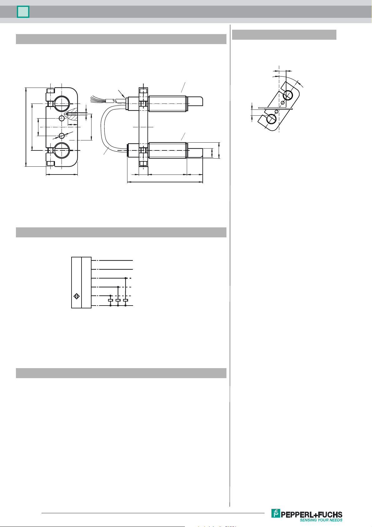
Dimensions
86
20
54
Additional Information
Mounting/Adjustment
(for very thick Papers)
wires 70 mm with
wire end ferrules
LEDs
l = 2 m
M6
11
ø6.3
36
30
l = 70 mm
Evaluation unit with
receiver unit
Emitter unit
4510
87
a
10
M18x1
18
β = 35˚
b
β
Electrical Connection
Standard symbol/Connection:
Double sheet control
U
Accessories
UC-PROG1-USB
Programming adapter
UDB-Cable-2M
UDB-Cable-1M
(BN)
(PK)
(WH)
(BK)
(GY)
(BU)
+U
B
Function input
Output single sheet
Output double sheet
Output air
-U
B
V15S-G-0,3M-PUR-WAGO
Male cordset, M12, 5-pin, PUR cable with WAGO terminals
Ultraschall-Sensoren DTM
DTM devices for communication with cube style and UMC... sensors
PACTware 4.X
FDT Framework
Refer to “General Notes Relating to Pepperl+Fuchs Product Information”.
2
Release date: 2016-08-01 13:43 Date of issue: 2016-08-01 235851_eng.xml

Double sheet sensor UDC-18GMA-400-3E3
Description of sensor functions
The ultrasonic double sheet monitor is used for double sheet detection in all situations in which the automatic distinction between double and single sheets is required in order to protect machines or avoid waste production. The double-sheet monitor is based on the ultrasonic through-beam principle. The following can be detected:
- No sheet, i.e. air,
- Individual sheet
- Double sheet
A microprocessor system evaluates the signals. The appropriate switch outputs are set as a result of the evaluation. Changes in ambient conditions such as temperature and humidity are compensated for automatically. The interface electronics is integrated into a
compact M18 metal housing together with a sensor head.
Switching on
The sensor is equipped with 6 connections. The functionality of the connections is described in the following table. The function input
(PK) is used to assign parameters to the sensor. (See Output pulse extension, Alignment aid and Program selection). During normal
operation, the function input must always be securely connected with +U
lity.
Colour Switching on Comments
BN +U
WH Switch output for single sheets Pulse width corresponds to the event
BK Switch output for double sheets Pulse width corresponds to the event
GY Switch output for air Pulse width corresponds to the event
PK -U
BU -UB
B
B
/+U
B
Function input for parameter assignment/
pulse prolongation
or -UB, to avoid possible interference or improper functiona-
B
Normal mode
The sensor is working in normal mode if the function input (PK) is applied to -UB or +UB when the power source (Power-On) is supplied,
as shown in the output pulse extension table (see below).
Displays:
LED yellow: Detection of air
LED green: Detection of single sheets
LED red: Detection of double sheets
Switch outputs:
The switch outputs are only active in normal operation!
White: WH Single sheet output
Black: BK Double sheet output
Gray: GY Air output
Output pulse extension
Switching the function input (PK) on to -UB or +UB makes it possible to select a minimum pulse width of 120 ms for all output pulses of
the three switch outputs.
Switching on (PK) Operating behaviour (after Power-On)
-U
B
+U
B
Please note:
This can result in a condition in which more than one switch output is switched through!
Display Mode
The selected parameter assignment of the sensor can be displayed by switching the function input (PK) to voltage-free during normal
operation. The green LED displays the program number (the number of flashing pulses (1 ... 4) = the program number).
The outputs are inactive during this time.
If the function input (PK) is switched to voltage-free when power is supplied (Power-On), the sensor will also work in display mode.
If the unit is switched to voltage-free while the function input (PK) is in operation due to an error (broken cable, coming loose because
of vibration), display mode acts as a fault display.
No output pulse extension for switch outputs
Output pulse extension of all switch outputs to at least 120 ms
Parameter assignment
The sensor is equipped with 4 programs for different ranges of application. This makes it possible to work with a wide range of material.
The user can select the program best suited for a specific application.
The default setting, Program 1, is designed so that no change in the setting is required for most applications.
Programs
Program number Notes: Range of materials
1 Default setting, standard paper
2 Thick paper, cardboard, fine corrugated
boards(DIN 55 468--1)and thin sheet metal**
Release date: 2016-08-01 13:43 Date of issue: 2016-08-01 235851_eng.xml
Refer to “General Notes Relating to Pepperl+Fuchs Product Information”.
3 Thin paper
20 - 1200 g/m
> 100 g/m
20 – 250 g/m
2
2
2
3

Double sheet sensor UDC-18GMA-400-3E3
4 Extremely fine paper
< 40 g/m
2
*) The measurements were made under the following conditions: d = 45 mm, a = 10 mm, β = 0°
*) The measurements were made under the following conditions: d = 45 mm, a = 10 mm,
β
= 35°
Procedure for assigning parameters
It is possible to switch to additional parameter assignment modes from the display mode:
Alignment mode -->
Program selection mode -->
Alignment aid mode --> (for checking)
When the function input (PK) is applied to -U
ching on function input (PK) on to +U
B
(for > 500 ms), the mode changes. When the "Program selection“ mode is active, swit-
B
(for > 500 ms) selects the next program level.
Disconnecting the power supply causes the system to exit the current mode with the selected program change.
The switch outputs are not active while parameters are being assigned to the sensor!
... and function input (PK)
Power ON Normal mode
... and function input
(PK) unconnected
connected to +U
Indication mode
-U
B
Alignment aid
(yellow LED)
B
or -U
-U
B
Indication mode
B
Program select
(green LED)
-U
B
Function input
(PK) unconnected
activate/deactivate
+U
B
output pulse
prolongation
+U
B
no function toggle cyclically
+U
B
next program
Modes
Amplitude control
During installation, the amplitude control can be used to check whether the ultrasonic amplitude at the receiver is sufficient. If the trans-
mitter is not aligned properly in relation to the receiver, maximum sound energy is not transmitted to the receiver, which may result in
the incorrect detection of materials.
When the sensor detects an area of air (yellow LED lights up), the UDC begins to display the strength of the measured amplitude signal:
- if the signal is weak, the yellow LED flashes at low frequency
- the flashing frequency increases in line with the signal strength
- the yellow LED lights up continuously when the signal strength is sufficient.
The single sheet function (green LED) and double sheet function (red LED) are now active. This can be used to check the correct
function of the sensor.
Program selection
In the program selection mode, the current program is displayed by the green LED (number of flashing pulses = program number).
Applying the adjustment input (PK) to +U
(for > 500 ms) causes the next program to be selected in cyclic sequence (program 1 fol-
B
lows through to program 4).
Notes:
A complete device consists of an ultrasonic emitter and an evaluation unit with an ultrasonic emitter. The sensor heads are optimally
adjusted to each other when they leave the factory. Therefore, they must not be used separately or exchanged with other devices of
the same type. The plug connector on the emitter/receiver connection cable is only intended to be used for easier mounting, not to
replace units.
Very light papers (for example handkerchiefs) or perforated papers are not always suitable for double sheet detection because of their
physical characteristics.
If two or more double sheet controls are used in the immediate vicinity of each other, there may be mutual interference between them,
which can result in improper functionality of the devices. Mutual interference can be prevented by introducing suitable countermeasures
when planning systems.
When installing, care has to be taken that the ultrasonic signal cannot pass around the material that is to be detected, due to
multiple reflections. This can happen if large surfaces are present at right angles to the direction of sound propagation. This can
be the case if unsuitable mounting brackets are used, or if assemblies with large surface are part of the machine. In the latter
case such machine parts should be covered by sound absorbing material or a different location for the installation should be
chosen.
Parameterization using PACTwa re DTM
The double sheet sensor can be connected using a V15S-G-0.3M-PUR-WAGO terminal adapter.
Release date: 2016-08-01 13:43 Date of issue: 2016-08-01 235851_eng.xml
Refer to “General Notes Relating to Pepperl+Fuchs Product Information”.
4

Double sheet sensor UDC-18GMA-400-3E3
M12 socket for
the UC-PROG1
V15S-G-0.3M-PUR-WAGO
Connection cable for
the double sheet sensor
Connect the sensor to the terminal adapter according to the table below.
Terminal adapter wire color Sensor cable wire color
Brown Brown
Blue Blue
Black Black
Gray Pink
The sensor features a time lock. If no communication request occurs, the time lock blocks parameterization of the sensor 30 seconds
after the supply voltage is connected. Start PACTware before switching on the sensor so that the communication request can be made
in time.
Release date: 2016-08-01 13:43 Date of issue: 2016-08-01 235851_eng.xml
Refer to “General Notes Relating to Pepperl+Fuchs Product Information”.
5
 Loading...