

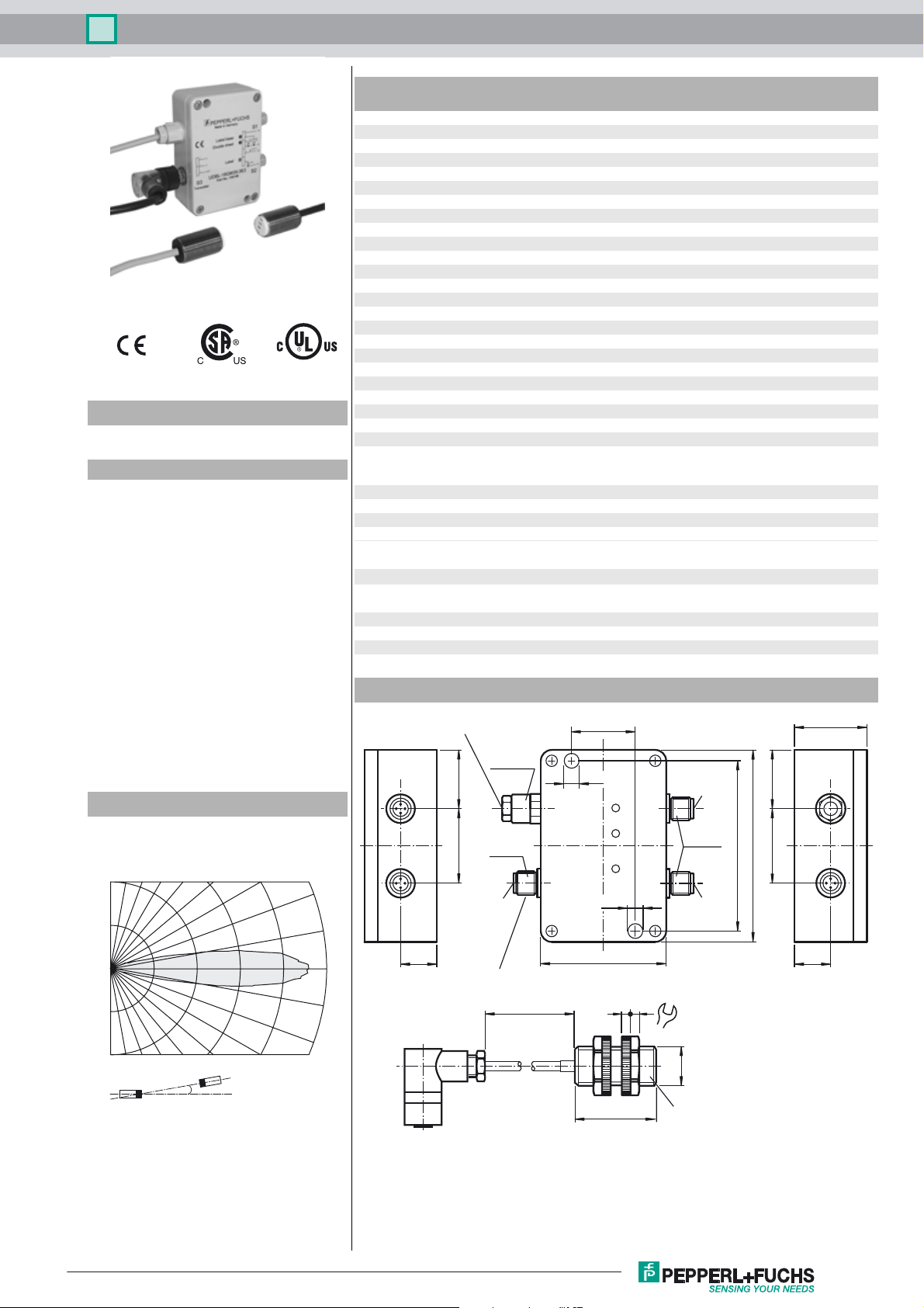
Splice sensor UDBK-18GM35-3E2
Technical data
General specifications
Transducer frequency 180 kHz
Indicators/operating means
LED green indication: single sheet detected
LED yellow indication: no sheet detected
LED red indication: double sheet or contact spot detected
Electrical specifications
Model Number
UDBK-18GM35-3E2
Features
• Ultrasonic system for detection of
single and pasted double sheet
• Weights of paper from 30 g up to
cartons weighing over 1200 g can
be detected
• It is also possible to detect thin
metal and plastic films.
• Various materials and thicknesses
are programmed in using a
TEACH-IN signal
• Automatic compensation of the
operating point with slowly
changing ambient condition
• Signal output via short-circuit
proof PNP switch outputs
• Very high processing speeds are
possible.
Diagrams
Operating voltage U
No-load supply current I
Input
Input type 1 pulse input for Teach-In
Pulse length ≥ 100 ms
Impedance ≥ 10 kOhm
Voltage 12 ... 30 V
Output
Output type 3 switch outputs PNP, NO
Rated operating current I
Voltage drop U
Switch-on delay t
Switch-off delay t
Ambient conditions
Ambient temperature 0 ... 60 °C (32 ... 140 °F)
Storage temperature -40 ... 70 °C (-40 ... 158 °F)
Mechanical specifications
Connection type emitter: V1-W connector with 2.5 m cable
Degree of protection IP65
Material
Housing Makrolon/nickel-plated brass
Mass 370 g
Compliance with standards and
directives
Standard conformity
Standards EN 60947-5-2:2007 + A1:2012
Approvals and certificates
UL approval cULus Listed, General Purpose
CSA approval cCSAus Listed, General Purpose
CCC approval CCC approval / marking not required for products rated ≤36 V
B
0
e
d
on
off
Dimensions
Connector Receiver
M12 x 1.5
3038
20 ... 30 V DC , ripple 10 %
< 80 mA
3 x 200 mA
≤ 2 V
≤ 1 ms
≤ 100 ms
receiver: 2.5 m fixed cable (not disconnectable)
S1,S2: 2 connectors V1-W, M12x1 (included with delivery)
IEC 60947-5-2:2007 + A1:2012
36
6.8
S1
SS
3038
37
Characteristic response curves
90 80 70 60 50 40 30
0.0
0.2
0.4
Distance [m]
Release date: 2016-04-25 09:35 Date of issue: 2016-04-25 106195_eng.xml
Refer to “General Notes Relating to Pepperl+Fuchs Product Information”.
0.6 0.8 1.0
α
Angle [degrees]
20
10
0
-10
-20
18.5
M12 x 1
S3
Connector Emitter
2.5 m
M12 x 1
6.8
64
44
S2
98
86
18.5
24
M18 x 1
35
Ultrasonic-Transducer (Emitter)
1
Splice sensor UDBK-18GM35-3E2
Electrical Connection
Standard symbol/Connection:
Double-sheet-control
U
Pinout
Connector V1
3
Additional Information
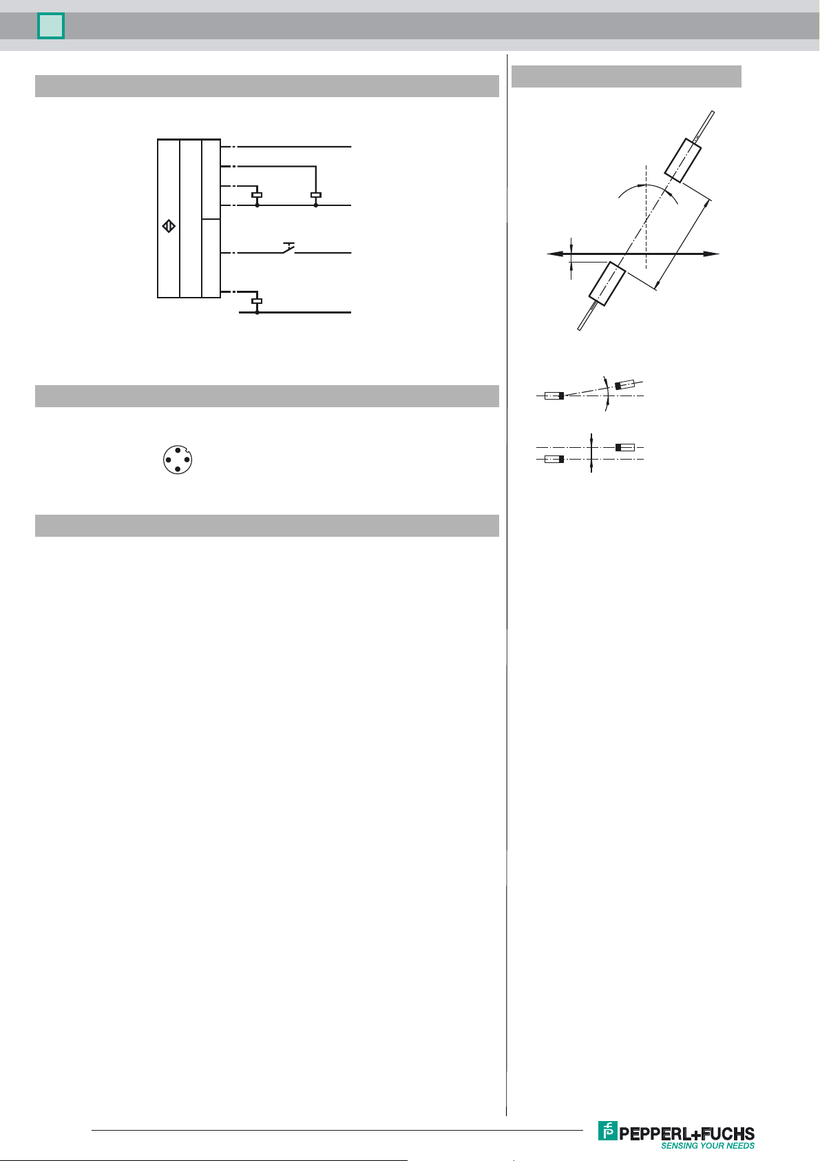
Mounting/Adjustment
Receiver
S1
S2
1
2
4
3
2
4
Double sheets
or splices
TEACH-IN key
No sheet
Single
sheet
+U
B
Relative position
-U
B
+U
B
-U
B
Paper position:
about 5 ... 15 mm above
the emitter
Angular alignment
α < +/- 2˚
Sensor offset
2
1
4
s < +/- 2 mm
20 ... 45˚
Emitter
(black cable)
α
s
(yellow cable)
d = 20 ... 80 mm
Accessories
MH-UDB01
Mounting bracket for double sheet monitor
Description of the sensor functions
Ultrasonic double-sheet monitoring to detect splice points is used in all situations in which
an automatic distinction must be made between splice points and double sheets in order
to protect machines or avoid waste production. Double-sheet monitoring for splice point
detection is based on the ultrasonic through-beam principle. The following can be detected:
- No sheet
- Individual sheet
- Splice point or double sheet
A microprocessor system evaluates the signals. The appropriate switch outputs are set
as a result of the evaluation. Changes in ambient conditions such as temperature and
humidity are automatically compensated. The evaluation electronics are installed in a
cuboid plastic housing separate from the sensor heads.
Measuring system
A complete system consists of an ultrasonic emitter, an ultrasonic receiver and an evaluation unit. These units have been optimally tuned to one another at the factory and may
not be used separately.
Alignment
When adjusting the emitter and receiver, take care to align them as precisely as possible.
Distance of the sensor heads: d = 20 mm ... 80 mm
Angular tolerance: α < +/- 2°
Maximum offset: s < +/- 2 mm
To ensure their correct function, the sensor heads must be aligned at an angle of
20° ... 45° from vertical onto the paper surface. The paper is guided over the emitter at a
distance of 5 mm ... 15 mm. The emitter is installed below in order to prevent dust deposits. Install the sensor heads using the included plastic nuts. The sound cone must be
completely covered by the paper. This means that the sensor heads must be installed
above the sheet of paper and at least 10 mm away from the side edge of the paper.
Feed speed of the sheet (approximate value)
v
= 0.035 m/s
min
v
[m/s] = overlapping of sheets [mm] / 1 ms (approx. value, overlapping > 20 mm)
max
Teach-In
2
Refer to “General Notes Relating to Pepperl+Fuchs Product Information”.
Release date: 2016-04-25 09:35 Date of issue: 2016-04-25 106195_eng.xml

Splice sensor UDBK-18GM35-3E2
1. After the operating voltage has been applied, a single sheet can be fed in as the first sheet. It will automatically be programmed as a reference value
by the system.
2. If a single sheet of paper is located between the ultrasonic emitter and receiver when the operating voltage is turned on, it will automatically be programmed as
a reference value by the system.
Automatic learning for thinner types of sheets
If you are inserting a thinner type of sheet, you can dispense with the use of the Teach-In signal to program the system. In order to do
this, a single sheet of paper must be between the emitter and receiver for at least 2 s.
Automatic learning for thicker types of sheets
If you are inserting a thicker type of sheet but still not one that will result in double-sheet output, you can dispense with learning by
means of the Teach-In signal. In order to do this, a single sheet of paper must be between the emitter and receiver for at least 2 s.
Teach-In for new type of sheet
If you are inserting a new type of sheet that will result in double-sheet output, the system must be reprogrammed. To do this, a single
sheet must be placed between the emitter and receiver. After the Teach-In signal has been applied, the corresponding reference value
will be accepted.
Caution!
The paper sheets may not touch the sensor heads during operation. Depending on physical conditions, reflections on the
edge of a single sheet may result in double-sheet output. This is not an error, and can be masked out in the higher-level control system.
Sensor systems for ultrasonic double-sheet monitoring can also be delivered with a customised time response for optimal adaptation
to specific applications.
Notes:
When installing, care has to be taken that the ultrasonic signal cannot pass around the material that is to be detected, due to multiple
reflections. This can happen if large surfaces are present at right angles to the direction of sound propagation. This can be the case if
unsuitable mounting brackets are used, or if assemblies with large surface are part of the machine. In the latter case such machine
parts should be covered by sound absorbing material or a different location for the installation should be chosen.
In cases where more than one system is needed per machine, acoustic isolation should be provided to avoid cross-talk. This can be
provided, for example, by appropriately positioning isolation panels.
Release date: 2016-04-25 09:35 Date of issue: 2016-04-25 106195_eng.xml
Refer to “General Notes Relating to Pepperl+Fuchs Product Information”.
3
 Loading...