

Ultrasonic sensor UCC2000-30GH70-IE2R2-K-V15
Technical data
General specifications
Sensing range 100 ... 2000 mm
Adjustment range 150 ... 2000 mm
Dead band 0 ... 100 mm
Standard target plate 100 mm x 100 mm
Transducer frequency approx. 200 kHz
Response delay ≤ 100 ms
Nominal ratings
Temperature drift ≤ ± 1.5 % of full-scale value
Model Number
UCC2000-30GH70-IE2R2-K-V15
Ultrasonic diffuse sensor with separate
transducer
Features
• Analog output 4 ... 20 mA
•1 switch output
• Temperature compensation
• Synchronization options
• Can be parameterized via the
ULTRA-PROG-IR software and
interface (accessories)
• High chemical resistance through
FEP coated transducer surface
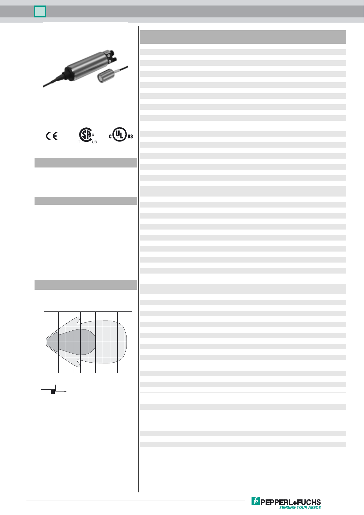
Diagrams
Characteristic response curve
Distance Y [mm]
500
250
0
-250
-500
0 250 500 750 1000 1250 1500 1750 2000 2250 2500 2750 3000
Y
Curve 1: flat surface 100 mm x 100 mm
Curve 2: round bar, Ø 25 mm
2
X
1
Distance X [mm]
Time delay before availability t
Limit data
Permissible cable length max. 300 m
Indicators/operating means
LED yellow switching state switch output
LED green/yellow yellow: object in evaluation range
Potentiometer switch output adjustable
Electrical specifications
Rated operating voltage U
Operating voltage U
Ripple ≤ 10 %
No-load supply current I
Interface
Interface type Infrared
Mode point-to-point connection
Input/Output
Input/output type 1 synchronization connection, bidirectional ( Factory setting:
0 Level ≤ 3 V
1 Level ≥ 15 V
Input impedance typ. 900 Ω
Number of sensors max. 10
Switching output
Output type 1 switch output PNP, NO ( NC contact programmable )
Default setting 150 ... 2000 mm ( adjustable via potentiometer )
Repeat accuracy R ± 3 mm
Operating current I
Switching frequency ≤ 4 Hz
Switching hysteresis 20 mm ( programmable )
Voltage drop ≤ 3 V
Off-state current ≤ 10 µA
Analog output
Output type 1 current output 4 ... 20 mA , ascending/descending
Default setting rising ramp ; evaluation limit A1: 150 mm ; evaluation limit A2:
Load resistor ≤ 500 Ω
Ambient conditions
Ambient temperature -25 ... 70 °C (-13 ... 158 °F)
Storage temperature -40 ... 85 °C (-40 ... 185 °F)
Shock resistance 30 g , 11 ms period
Vibration resistance 10 ... 55 Hz , Amplitude ± 1 mm
Mechanical specifications
Connection type Connector M12 x 1 , 5-pin
Degree of protection IP65
Material
Housing Stainless steel 1.4571 / AISI 316Ti plastic PBT
Cable PVC
Transducer FEP coated; epoxy resin/hollow glass sphere mixture;
Installation position any position
Mass 190 g
Construction type Cylindrical
Cable length 165 cm
Compliance with standards and
directives
Standard conformity
Standards EN 60947-5-2:2007+A1:2012
Approvals and certificates
UL approval cULus Listed, General Purpose
CSA approval cCSAus Listed, General Purpose
CCC approval CCC approval / marking not required for products rated ≤36 V
B
L
v
e
0
≤ 125 ms
green: Teach-In
24 V DC
20 ... 30 V DC (including ripple)
≤ 50 mA
synchronized mode ) / Teach-In input
300 mA , short-circuit/overload protected
programmable
2000 mm
polyurethane foam
IEC 60947-5-2:2007 + A1:2012
EN 60947-5-7:2003
IEC 60947-5-7:2003
Release date: 2017-04-03 09:55 Date of issue: 2017-04-03 238427_eng.xml
Refer to “General Notes Relating to Pepperl+Fuchs Product Information”.
1
Ultrasonic sensor UCC2000-30GH70-IE2R2-K-V15
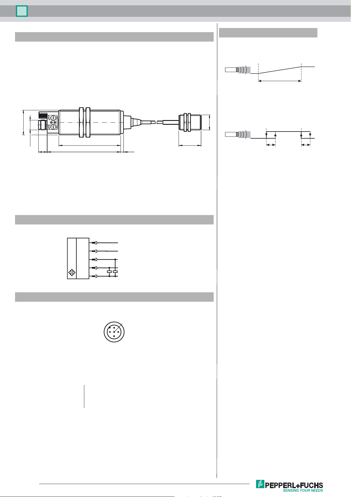
Dimensions
M30 x 1.5
M12 x 1
10.5 88.5 3.3
74.4
26.7
Additional Information
Analog output operating mode
Rising ramp
Evaluation limit A1
Blind zone
Evaluation range
Switching output operating mode
Window operation mode
M18 x 1
Blind zone
switching
point 1
Evaluation limit A2
switching
point 2
h2h1
Electrical Connection
Pinout
Wire colors in accordance with EN 60947-5-2
1 BN
2 WH
3 BU
4 BK
5 GY
1
2
4
5
3
2
1
3
(brown)
(white)
(blue)
(black)
(gray)
L+
XI
Switch output
Analog output
L-
5
4
Release date: 2017-04-03 09:55 Date of issue: 2017-04-03 238427_eng.xml
Refer to “General Notes Relating to Pepperl+Fuchs Product Information”.
2
 Loading...