

Ultrasonic sensor UC800-F77S-IU-IO-V31
Model Number
UC800-F77S-IU-IO-V31
Single head system
Features
• IO-Link interface for
parameterization
• Programmable via DTM with
PACTWARE
• Selectable sound lobe width
• Synchronization options
• Temperature compensation
•Analog output
Diagrams
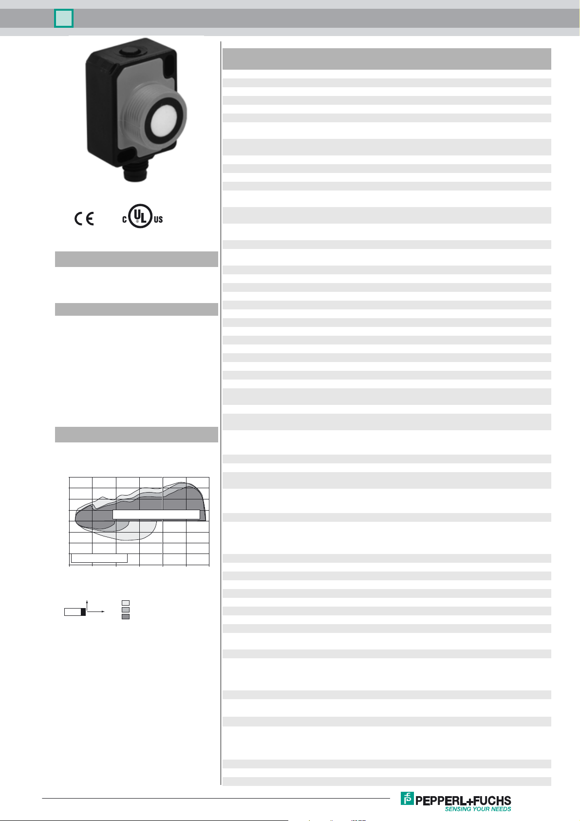
Characteristic response curve
Distance Y [mm]
200
150
100
50
0
-50
-100
-150
round bar, Ø 25 mm
-200
0 200 400 600 800 1000 1200
Release date: 2017-10-24 11:49 Date of issue: 2017-10-27 261248_eng.xml
Refer to “General Notes Relating to Pepperl+Fuchs Product Information”.
flat surface 100 mm x 100 mm
Y
wide sound beam
medium-sized sound beam
X
narrow sound beam
Distance X [mm]
Technical data
General specifications
Sensing range 60 ... 800 mm
Adjustment range 70 ... 800 mm
Dead band 0 ... 60 mm
Standard target plate 100 mm x 100 mm
Transducer frequency approx. 255 kHz
Response delay minimum : 13 ms
Sensor cycle time ≥ 13 ms (factory setting) ;
Memory
Non-volatile memory EEPROM
Write cycles 300000
Indicators/operating means
LED green solid: Power on
LED yellow solid: object in evaluation range
LED red solid: fault
Electrical specifications
Operating voltage U
No-load supply current I
Power consumption P
Time delay before availability t
Interface
Interface type IO-Link (after individual activation via programming button)
Input/Output
Input/output type 1 synchronization connection, bidirectional
0 Level 0 ... 1 V
1 Level 2.5 V ... U
Input impedance > 22 kΩ
Output rated operating current current source < 2.5 mA
Pulse length ≥ 1 ms with external control, low active
Synchronization frequency
Common mode operation ≤ 82 Hz
Multiplex operation ≤ 82 Hz / n , n = number of sensors , n ≤ 10
Output
Output type 1 analog output 0 (4) ... 20 mA or
Resolution current output: evaluation range [mm]/3200 but ≥ 0.35 mm
Deviation of the characteristic curve ≤ ± 1 % of full-scale value
Repeat accuracy ≤ ± 0.1 % of full-scale value
Load impedance current output: ≤ 500 Ohm
Temperature influence ≤ ± 0.75 % of the end value (with temperature compensation)
Ambient conditions
Ambient temperature current output -25 ... 60 °C (-13 ... 140 °F)
Storage temperature -40 ... 85 °C (-40 ... 185 °F)
Mechanical specifications
Connection type Connector plug M8 x 1 , 4-pin
Degree of protection IP67
Material
Housing Polycarbonate
Transducer epoxy resin/hollow glass sphere mixture; polyurethane foam
Installation position any position
Mass 13 g
Tightening torque, fastening screws with M3 nuts max. 0.2 Nm
Factory settings
Output near limit: 70 mm
Beam width wide
Compliance with standards and
directives
Standard conformity
Standards EN 60947-5-2:2007+A1:2012
Approvals and certificates
UL approval cULus Listed, Class 2 Power Source
CCC approval CCC approval / marking not required for products rated ≤36 V
B
0
0
v
factory setting: 49 ms
programmable to 60 s
flashing: Standby mode or IO-Link communication
flashing: programming of the limits, object detected
Flashing: programming limits, object not detected
18 ... 30 V DC , ripple 10 %SS
≤ 50 mA
≤ 500 mW
≤ 300 ms
B
1 analog output 0 ... 10 V
voltage output: evaluation range [mm]/4000 but ≥ 0.35 mm
voltage output: ≥ 1000 Ohm
from 10 minutes after switching on the sensor ; 0,17 %/K
(without temperature compensation)
voltage output -25 ... 70 °C (-13 ... 158 °F)
When fixing with one M18 nut, the temperature range for
each begins with 0 °C (32 °F).
with M18 nuts max. 1 Nm
far limit: 800 mm
Output mode: rising ramp
output type: 4 ... 20 mA
IEC 60947-5-2:2007 + A1:2012
EN 60947-5-7:2003
IEC 60947-5-7:2003
1
Ultrasonic sensor UC800-F77S-IU-IO-V31
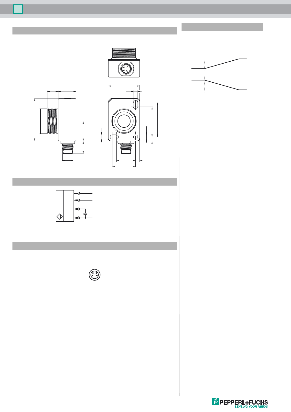
Dimensions
31
M18 x 1
8 13
M8 x 1
14.6
9
3.2
Additional Information
Analog output modes
Near limit
(SP 1)
Rising ramp
Falling ramp
23
3.2
25
22
ø3.2
3
3
14
17
Far limit
(SP 2)
Electrical Connection
*if not used connect to ground (0V)
Pinout
Wire colors in accordance with EN 60947-5-2
1 BN
2 WH
3 BU
4 BK
1
2
4
3
L+
Synchronization*
Analog output/
IO-Link Interface
L-
24
13
(brown)
(white)
(blue)
(black)
Release date: 2017-10-24 11:49 Date of issue: 2017-10-27 261248_eng.xml
Refer to “General Notes Relating to Pepperl+Fuchs Product Information”.
2
 Loading...