

Ultrasonic sensor UC500-F65-E8R2-V15
Technical data
General specifications
Sensing range 60 ... 500 mm
Adjustment range 60 ... 500 mm
Dead band 0 ... 60 mm
Standard target plate 10 mm x 10 mm
Transducer frequency approx. 300 kHz
Nominal ratings
Model Number
UC500-F65-E8R2-V15
Features
• Level indication
•2 switch outputs
• Program input
• Programmable by means of Interface (see accessories) and SONPROG
• Synchronization options
• Temperature compensation
Diagrams
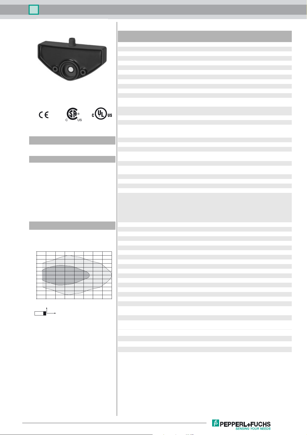
Characteristic response curve
Distance Y [mm]
150
125
100
75
50
25
0
-25
-50
-75
-100
-125
-150
0 100 200 300 400 500 600 700 800
Y
Curve 1: flat surface 100 mm x 100 mm
Curve 2: round bar, Ø 25 mm
2
X
1
Distance X [mm]
Time delay before availability t
Limit data
v
Permissible cable length max. 300 m
Indicators/operating means
LED green Power on
LED yellow 1 solid: switching state switch output 1
LED yellow 2 solid: switching state switch output 2
Electrical specifications
Rated operating voltage U
Operating voltage U
e
B
Ripple ≤ 10 %
No-load supply current I
Input
0
Input type 1 program input
Input voltage ≤ Operating voltage
Level low level : 0 ... 3 V (Teach-In active)
Pulse length ≥ 150 ms
Output
Output type 2 switch outputs PNP, NO
Rated operating current I
Default setting Switching distance "full", S
Voltage drop U
Switch-on delay t
d
Repeat accuracy ± 0.45 mm
Off-state current I
Temperature influence ≤ ± 1.5 %
e
on
r
Ambient conditions
Ambient temperature -25 ... 70 °C (-13 ... 158 °F)
Storage temperature -40 ... 85 °C (-40 ... 185 °F)
Shock resistance 30 g , 11 ms period
Vibration resistance 10 ... 55 Hz , Amplitude ± 1 mm
Mechanical specifications
Connection type Connector M12 x 1 , 5-pin
Degree of protection IP65
Material
Housing PBT
Transducer epoxy resin/hollow glass sphere mixture; polyurethane foam
Installation position any position
Mass 500 g
Compliance with standards and
directives
Standard conformity
Standards EN 60947-5-2:2007 + A1:2012
250 ms
flashing: misadjustment
flashing: misadjustment
24 V DC
12 ... 30 V (including ripple)
In supply voltage interval 12 ... 20 V sensitivity reduced to
20% ... 0%
≤ 60 mA
Teach-In of S
min
high level : ≥ 15 V (Teach-In inactive)
150 mA , short-circuit/overload protected
: 80 mm
Smax
max
: 20
Smin
min
Smax
: 110
: 450 mm
: 20 mm
: 100 mm
Smin
Switching distance "empty", S
Switching hysteresis "full", H
Switching hysteresis "empty", H
average value "full", M
average value "empty", M
≤ 3 V
80 ms
0.01 mA
IEC 60947-5-2:2007 + A1:2012
Release date: 2016-02-16 08:26 Date of issue: 2016-02-16 235136_eng.xml
Refer to “General Notes Relating to Pepperl+Fuchs Product Information”.
Approvals and certificates
UL approval cULus Listed, General Purpose
CSA approval cCSAus Listed, General Purpose
CCC approval CCC approval / marking not required for products rated
≤36 V
1
Ultrasonic sensor UC500-F65-E8R2-V15
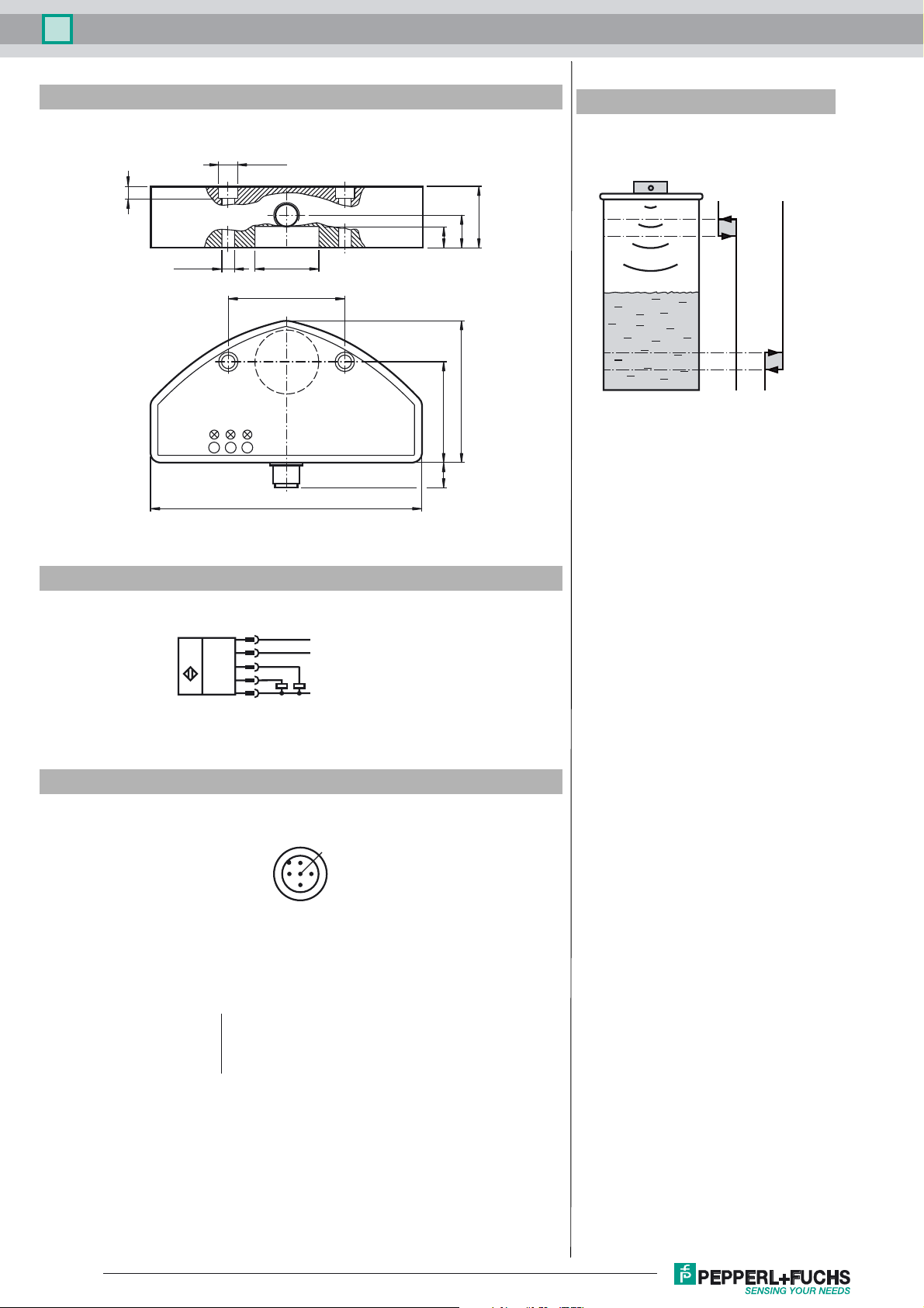
Dimensions
Additional Information
Function of the switching outputs
2 x ø8.8
Sensor
Sensor
6
)
Q2 (S
30
17
10
2 x ø5.5
ø30
54
64.4
1
4612
125
max
)
min
Q1 (S
H
S
max
H
S
min
0
1
0
Electrical Connection
Pinout
Wire colors in accordance with EN 60947-5-2
1 BN
2 WH
3 BU
4 BK
5 GY
1
2
4
5
3
2
+ U
B
XI
Q1 (S
)
min
Q2 (S
)
max
- U
B
1
5
4
3
(brown)
(white)
(blue)
(black)
(gray)
Release date: 2016-02-16 08:26 Date of issue: 2016-02-16 235136_eng.xml
Refer to “General Notes Relating to Pepperl+Fuchs Product Information”.
2

Ultrasonic sensor UC500-F65-E8R2-V15
Accessories
V15-G-2M-PUR
Female cordset, M12, 5-pin, PUR cable
V15-G-2M-PVC
Female cordset, M12, 5-pin, PVC cable
V15-W-2M-PVC
Female cordset, M12, 5-pin, PVC cable
3RX4000-PF
PC interface
Applications
The design and functionality makes this sensor best suitable for level detection applications in small containers or tanks. The device provides 2 switching outputs Q1 (S
and Q2 (S
be programmed with SONPROG or with an automatic setup (Teach-In).
). Special distances can be assigned to each of them - e. g. the minimum and maximum levels in a tank can be evaluated and displayed. The parameters can
max
Mounting and Connection
All parts are accommodated in a fully enclosed housing. The ultrasonic transducer is set back in the housing, so it is protected. Because of the built-in sealing the sensor can
be used as a closure with integrated level detection. The opening of the tank must have a diameter of 26 mm. The sensor is fixed by means of two M5 screws. The sensor
has a 5 pin M12 x 1 connector. The BERO has built-in polarity reversal as well as short-circuit and overload protection. Where there is electrical interference, shielded cables
are recommended.
Setup
The two ranges, the associated hysteresis and the average value are preset at the factory (see technical data). The parameters can be programmed with SONPROG or with
an automatic setup (teach-in). Teach-in can be done by means of the keys of the interface (accessories) or the function input XI.
Automatic Setup (Teach-in)
With this function the minimum level S
can be set. The following steps must be performed in the correct order:
min
1. Fill the tank up to the required minimum level or place an object at the required distance.
2. Apply "low" signal (0 to 3 V) to the function input XI - e.g. connect XI via a key to 0 V, or connect it via a PLC to "LOW"). The LED "S
disabled; it‘s learning the distance. The signal duration must be at least 150 ms.
3. Remove signal from XI - e.g. disconnect it from the function input XI, connect it to +U
Important! As long as the function input XI is connected to "low", the sensor is disabled.
or connect it via a PLC to "HIGH").
B
" flashes, then. The sensor is
min
SONPROG
With SONPROG the following parameters can be programmed:
• Start or end of both switching ranges S
• Hysteresis (HS
max
, HS
min
)
min
and S
max
• Blind zone
• Sensing range
• Average value
• Switching output S
Customer specific programming is available on request.
NC / NO
min
Operation
The level of liquid inside a tank is detected within the sensing range. If the level reaches one of the two switching levels (S
, HS
active. Both switching levels are equipped with a switching hysteresis (HS
min
). The switching status of each output is indicated by the corresponding yellow LED. If the
max
, S
), then the corresponding output will be set
min
max
filling level is in between the 2 switching levels, both of the outputs are in off state.
Objects inside the blind zone will cause error signals. Therefore the user has to mount the sensor that way that the level cannot be inside the blind zone.
min
)
Release date: 2016-02-16 08:26 Date of issue: 2016-02-16 235136_eng.xml
Refer to “General Notes Relating to Pepperl+Fuchs Product Information”.
3
 Loading...