

Ultrasonic sensor UC500-D1-3K-V7
Technical data
General specifications
Sensing range 60 ... 550 mm
Dead band 0 ... 60 mm
Standard target plate 100 mm x 100 mm
Transducer frequency approx. 380 kHz
Model Number
UC500-D1-3K-V7
Single head system
Features
• Specially for level monitoring in
vessels
• Large operating voltage range
10 V DC ... 253 V DC
20 V AC ... 253 V AC
•3 relay outputs
• Parameter assignment via DIPswitches
• Temperature compensation
• Cable socket included with
delivery
Diagrams
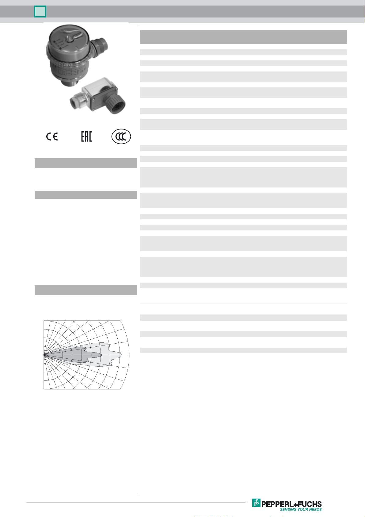
Characteristic response curves
90 80 70 60 50 40 30
0.0
0.1
0.2
0.3
0.4
Distance [m]
0.5 0.6 0.7 0.8 0.9
2
Angle [degrees]
1
-20
Response delay > 10 s, relay
Indicators/operating means
LED red LED 1: overfill indication
LED green/yellow LED 2: overfill warning and normal operation
DIP switch setting of the switch points/operating modes
Electrical specifications
Operating voltage U
S
No-load supply current I
Output
Output type 3 relay outputs, normally open/closed, selectable
Range hysteresis H 20 mm
Contact loading 253 V AC/150V DC, 3 A (ohm. load)
Life span electrical: 105 switching cycles with ohmic load
Temperature influence < 4 %
Fusing ≤ 3 A Slow-blow fuse per output in accordance with
Ambient conditions
Ambient temperature -20 ... 60 °C (-4 ... 140 °F)
Storage temperature -40 ... 85 °C (-40 ... 185 °F)
Mechanical specifications
Degree of protection IP65
Connection Female connector, V7 (7-pin), 90°
Material
Housing cover: PC
Transducer epoxy resin/hollow glass sphere mixture; polyurethane foam
Mass 700 g
Note In case of loss or damage, the cable socket mu st be replaced
Compliance with standards and
directives
Standard conformity
20
Standards EN 60947-5-2:2007+A1:2012
Approvals and certificates
EAC conformity TR CU 004/2011
10
CCC approval Certified by China Compulsory Certification (CCC)
-0
-10
B
0
< 1 s, LEDs
LED 4: underfill indication
LED 3: normal operation and underfill warning
10 ... 253 V DC
20 ... 253 V AC , 47 ... 63 Hz
< 30 mA with UB = 30 V DC
< 110 mA at U
< 25 mA at U
(3 A/253 V AC or 3 A/30 V DC)
minimum contact load: 100 µA/100 mV DC
mechanical: 20 x 10
IEC 60127-2 Sheet 5 required. Recommendation: after a
short circuit, check that the device is functioning correctly.
Wire cross section: ≤1.5 mm
= 10 V DC
B
= 220 V AC
B
6
switching cycles
2
cable diameter Ø7 ... 9 mm
housing: PBT
threaded flange: stainless steel
installation connector/cable socket: PETP
by an identical cable socket (type V7-W) from
Pepperl+Fuchs!
IEC 60947-5-2:2007 + A1:2012
TR CU 020/2011
Curve 1: flat surface 100 mm x 100 mm
Curve 2: round bar, Ø 25 mm
Release date: 2017-08-24 08:53 Date of issue: 2017-08-24 212371_eng.xml
Refer to “General Notes Relating to Pepperl+Fuchs Product Information”.
1
Ultrasonic sensor UC500-D1-3K-V7
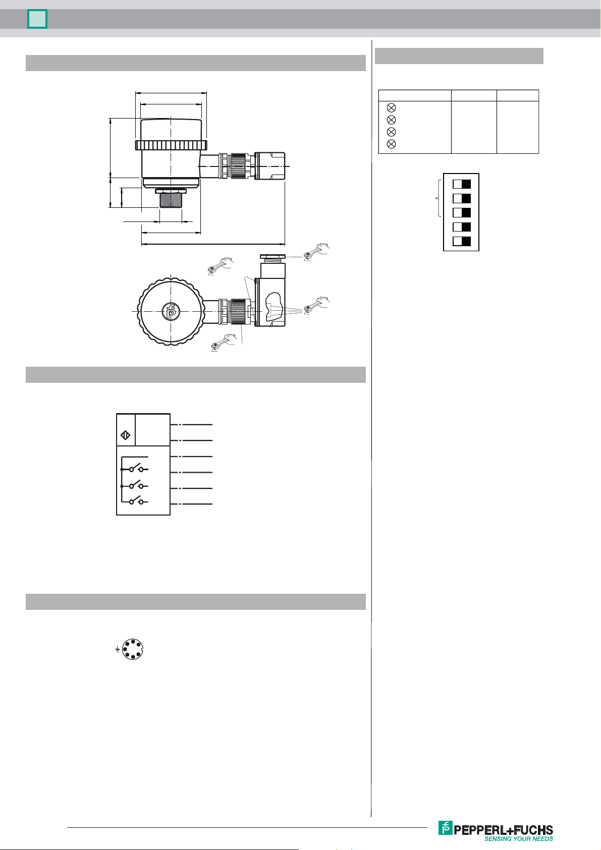
Dimensions
6838
28
M30 x 1.5
ø 75
ø 65
ø 64.5
144
0.4 ... 0.5 Nm
0.4 ... 0.5 Nm
2.5 ... 3.75 Nm
0.4 ... 0.5 Nm
Additional Information
Indicators/operating means
12345
S4 = OFF
full
high
normal
empty
ON
LED
1 (red)
2 (green/yellow)
3 (green/yellow)
4 (red)
switch output
adjustment
overspill warning
normal operation
S4 = ON
full
normal
low
empty
run-dry warning
TEACH-IN mode
Electrical Connection
Standard symbol/Connection:
U
Pinout
Connector V7
1
2
1
2
U
B
U
B
3
4
A1
5
A2
6
A3
6
5
4
3
Release date: 2017-08-24 08:53 Date of issue: 2017-08-24 212371_eng.xml
Refer to “General Notes Relating to Pepperl+Fuchs Product Information”.
2

Ultrasonic sensor UC500-D1-3K-V7
Safety notes:
The supply circuit is separated from the relay circuit by basic insulation.
The cover may only be opened by specially trained personnel. Pollution degree 2 is permissible when
the cover is open. Ensure that the sealing ring of the cover is in good condition.
Protection class II is only guaranteed when using the recommended cable socket. The cable box may
only be separated from the unit when the power is off.
The connector pin 7 of the connector is not connected to the sensor. An eventually present earth connection in the cable socket therefore will not be looped into the sensor.
CAUTION:
The UC500-D1-K3-V7 ultrasonic sensor is not
Conformity: EN 60947-5-2
Housing insulation: Protection class II
Pollution degree: 4 (process face)
3 (housing- and connector side)
Overvoltage category: III
TEACH-IN of switching points:
One switching point can be taught for each of the 3 switch outputs. Set DIP switch 5 to ON to put the sensor in TEACH-IN mode.
The sensor indicates TEACH-IN mode with two lit red LEDs. The green-yellow LEDs are off.
Next, position a suitable target object at the desired switching point in front of the sensor and switch the DIP switch associated
with the relevant switch output (switches 1-3). The sensor will now be flashing yellow or green in addition to the lit red LEDs.
Flashing green indicates that the target object was detected; flashing yellow signals that it was not detected. The measured
switching point will be transferred to RAM when the associated DIP switch is switched back while the LED is flashing green.
Only the red LEDs should now be lit. This signals the user that the DIP switches 1-3 have been restored to their original positions. The other switching points are set in the same manner. The TEACH-IN procedure is completed by setting DIP switch 5
back to the OFF position. The measured switching points will then be transferred to the nonvolatile EEPROM.
Under normal circumstances, switching point A1 should be less than A2, and A2 less than A3. If this is not observed, the sensor
will automatically exchange the switching points after the TEACH-IN procedure is complete so that A1 < A2 < A3. This ensures
that the LEDs respond correctly and that the shortest switching point is assigned to relay 1, the middle distance to relay 2 and
the longest distance to relay 3.
If DIP switch 4 is switched during TEACH-IN, the default value for the switching point will be set rather than a target object. The
default values for the switching points are 60 mm for A1, 220 mm for A2 and 270 mm for A3.
suitable for use in environments subject to explosion hazards.
Display
DIP1-3 one or more DIP switches changed
DIP4 normal state
State object detected object not
during TEACH-IN:
TEACH-IN of object distance
TEACH-IN active
changed
default parameter
default active
in normal state
TEACH-IN complete
normal
changed
state
detected
LED 1, red lit lit lit lit lit
LED 2, green/yellow flashes green off lit green off lit green
LED 3, green/yellow off flashes yellow lit yellow off lit yellow
LED 4, red lit lit lit lit lit
The relays switch to the "safe state" (all relays open, regardless of close/open function) during TEACH-IN.
Setting the switching behaviour:
In normal mode (DIP switch 5 OFF), the DIP switches 1 to 3 can be used to set the switching behaviour of the switch outputs 1
to 3. If the associated DIP switch is ON, the associated switch output has a close function; if the switch is set to OFF the output
has an open function. Close function means that the relay trips when the object distance is less than the associated switching
point; in the case of open function, the relay trips when the object distance is greater than the switching point.
The relays switch to the "safe state" (all relays open, regardless of close/open function) in the event of a failure
Setting the display modes:
Two display modes can be selected with DIP switch 4:
Release date: 2017-08-24 08:53 Date of issue: 2017-08-24 212371_eng.xml
Refer to “General Notes Relating to Pepperl+Fuchs Product Information”.
3

Ultrasonic sensor UC500-D1-3K-V7
Display mode 1: DIP switch 4 ON, underfill warning:
Object distance x x < A1 A1 < x < A2 A2 < x < A3 x > A3
LED 1, red (full) flashes off off off
LED 2, green/yellow (normal) off lit green off off
LED 3, green/yellow (low) off off flashes yellow off
LED 4, red (empty) off off off flashes
In this mode LED 1 (red) serves as the overfilling indicator, LED 2 (green) indicates the normal state, LED 3 (yellow) serves as
the preliminary warning that the container is nearly empty and LED 4 (red) signalises the "container empty" state.
Display mode 2: DIP switch 4 OFF, overfill warning
Object distance x x < A1 A1 < x < A2 A2 < x < A3 x > A3
LED 1, red (full) flashes off off off
LED 2, green/yellow (high) off flashes yellow off off
LED 3, green/yellow (normal) off off lit green off
LED 4, red (empty) off off off flashes
In this mode LED 1 (red) serves as the overfilling indicator, LED 2 (yellow) serves as the preliminary warning that the container
is nearly full, LED 3 (green) indicates the normal state, and LED 4 (red) signalises the "container empty" state.
The relays switch to the "safe state" (all relays open, regardless of close/open function) in the event of a failure.
Release date: 2017-08-24 08:53 Date of issue: 2017-08-24 212371_eng.xml
Refer to “General Notes Relating to Pepperl+Fuchs Product Information”.
4
 Loading...