

Pepperl Fuchs UC400-F77-EP-IO-V31 Data Sheet
Ultrasonic sensor UC400-F77-EP-IO-V31
Model Number
UC400-F77-EP-IO-V31
Single head system
Features
• IO-link interface for service and
process data
• Programmable via DTM with
PACTWARE
• Continuous distance value via IOLink process data
• Selectable sound lobe width
• Synchronization options
• Temperature compensation
• Push-pull output
Diagrams
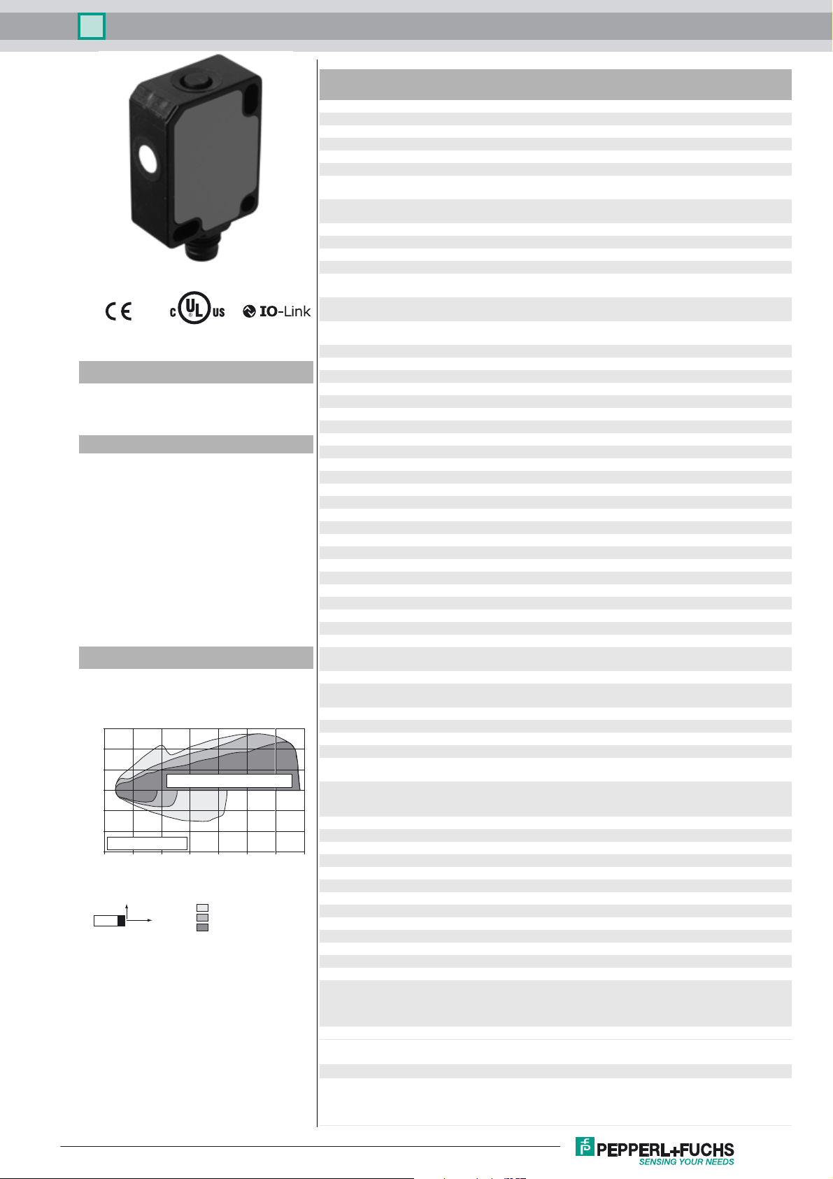
Characteristic response curve
Distance Y [mm]
150
100
50
0
-50
-100
round bar, Ø 25 mm
-150
0 100 200 300 400 500 600 700
Release date: 2018-04-18 13:58 Date of issue: 2018-04-18 261243_eng.xml
Refer to “General Notes Relating to Pepperl+Fuchs Product Information”.
flat surface 100 mm x 100 mm
Y
X
Distance X [mm]
wide sound beam
medium-sized sound beam
narrow sound beam
Technical data
General specifications
Sensing range 30 ... 400 mm
Adjustment range 40 ... 400 mm
Dead band 0 ... 30 mm
Standard target plate 20 mm x 20 mm
Transducer frequency approx. 310 kHz
Response delay minimum : 10 ms
Sensor cycle time ≥ 10 ms (factory setting) ;
Memory
Non-volatile memory EEPROM
Write cycles 300000
Indicators/operating means
LED green solid: Power on
LED yellow solid: object in evaluation range
LED red solid: error
Electrical specifications
Operating voltage U
No-load supply current I
Power consumption P
Time delay before availability t
Interface
Interface type IO-Link (via C/Q = Pin 4)
Device profile Smart Sensor
Transfer rate COM 2 (38.4 kBaud)
IO-Link Revision 1.1
Min. cycle time 2.3 ms
Process data witdh 16 bit
SIO mode support yes
Device ID 0x300301 (3146497)
Compatible master port type A
Input/Output
Input/output type 1 synchronization connection, bidirectional
0 Level 0 ... 1 V
1 Level 2.5 V ... U
Input impedance > 22 kΩ
Output rated operating current current source < 2.5 mA
Pulse length ≥ 1 ms with external control, low active
Synchronization frequency
Common mode operation ≤ 109 Hz
Multiplex operation ≤ 109 Hz / n , n = number of sensors , n ≤ 10
Output
Output type 1 push-pull (4 in 1) output, short-circuit protected, reverse
Rated operating current I
Voltage drop U
Repeat accuracy ≤ ± 0.1 % of full-scale value
Switching frequency f factory setting: 16 Hz programmable max. 35 Hz
Range hysteresis H 1 % of the adjusted operating range (default settings),
Temperature influence ≤ ± 0.75 % of the end value (with temperature compensation)
Ambient conditions
Ambient temperature -25 ... 70 °C (-13 ... 158 °F)
Storage temperature -40 ... 85 °C (-40 ... 185 °F)
Mechanical specifications
Connection type Connector plug M8 x 1 , 4-pin
Degree of protection IP67
Material
Housing Polycarbonate
Transducer epoxy resin/hollow glass sphere mixture; polyurethane foam
Installation position any position
Mass 9 g
Tightening torque, fastening screws max. 0.2 Nm
Factory settings
Output near switch point: 40 mm
Beam width wide
Compliance with standards and
directives
Standard conformity
Standards EN 60947-5-2:2007+A1:2012
B
0
0
v
e
d
factory setting: 37 ms
programmable to 60 s
flashing: Standby mode or IO-Link communication
flashing: switch point programming, object detected
flashing: switch point programming, object not detected
10 ... 30 V DC , ripple 10 %
≤ 40 mA
≤ 400 mW
≤ 300 ms
B
polarity protected
100 mA , short-circuit/overload protected
≤ 2.5 V
programmable , min. 1 mm
from 10 minutes after switching on the sensor ; 0,17 %/K
(without temperature compensation)
far switch point: 400 mm
Output mode: Window mode
Output logic: normally open
IEC 60947-5-2:2007 + A1:2012
IEC 61131-9:2013
SS
1
Ultrasonic sensor UC400-F77-EP-IO-V31
Approvals and certificates
UL approval cULus Listed, Class 2 Power Source
CCC approval CCC approval / marking not required for products rated ≤36 V
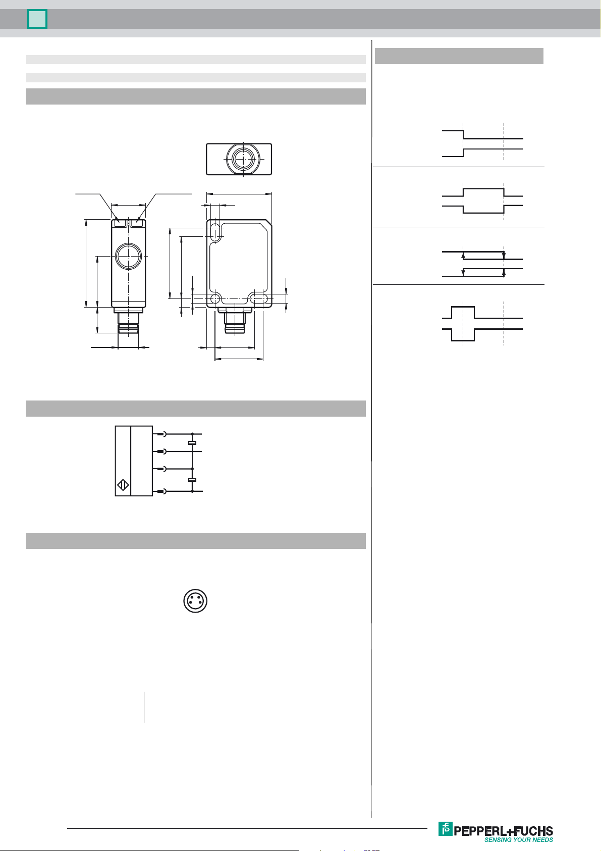
Dimensions
LED YE LED GN/RD
12
31
189
M8 x 1
25
322
ø3.2
23
3.2
3.2
3 14
17
Additional Information
Switching output modes
1. Switch point mode
Switch point 1
(SP 1)
Normally open
Normally closed
2. Window mode
Normally open
Normally closed
3. Hysteresis mode
Normally open
Normally closed
4. Retroreflective mode
Normally open
Normally closed
Switch point 2
(SP 2)
Electrical Connection
*if not used connect to ground (0V)
Pinout
Wire colors in accordance with EN 60947-5-2
1 BN
2 WH
3 BU
4 BK
1
2
4
3
24
13
(brown)
(white)
(blue)
(black)
L+
Synchronization*
C/Q (Switching output/
IO-Link Interface)
L-
Release date: 2018-04-18 13:58 Date of issue: 2018-04-18 261243_eng.xml
Refer to “General Notes Relating to Pepperl+Fuchs Product Information”.
2
 Loading...