

Ultrasonic sensor UC4000-30GM-IU-V1
Technical data
General specifications
Sensing range 500 ... 4000 mm
Unusable area 0 ... 500 mm
Standard target plate 100 mm x 100 mm
Transducer frequency approx. 85 kHz
Response delay ≤ 300 ms
Indicators/operating means
Model Number
UC4000-30GM-IU-V1
Single head system
Features
• Analog current and voltage output
• 12 bit D/A transducer
• Evaluation limits can be taught-in
• Temperature compensation
• Compact design
• Plug connection
Diagrams
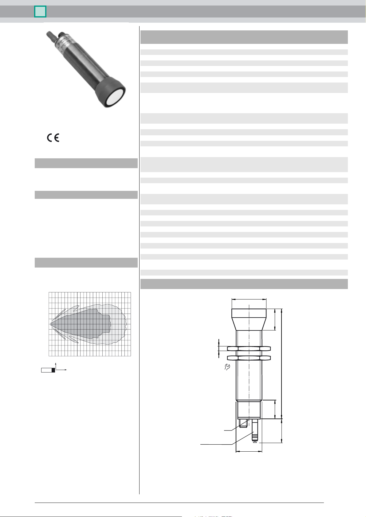
Characteristic response curve
Distance Y [m]
1.5
1.0
LED yellow solid yellow: object in the evaluation range
LED red/green solid green: Power on
Temperature/TEACH-IN connector Temperature compensation , Evaluation range
Electrical specifications
Operating voltage U
Power consumption P
Output
B
0
Output type 1 current output 4 ... 20 mA
Resolution depending on the set evaluation range:
Deviation of the characteristic curve ≤ 0.2 % of full-scale value
Repeat accuracy ≤ 0.1 % of full-scale value
Load impedance current output: ≤ 500 Ohm
Temperature influence < 2 % of full-scale value (≤ 0.2 % / K without temperature
Standard conformity
Standards EN 60947-5-2
Ambient conditions
Ambient temperature -25 ... 70 °C (-13 ... 158 °F)
Storage temperature -40 ... 85 °C (-40 ... 185 °F)
Mechanical specifications
Connection type Connector M12 x 1 , 4-pin
Protection degree IP65
Material
Housing High grade stainless steel
Transducer epoxy resin/hollow glass sphere mixture; foam
Mass 210 g
Dimensions
yellow, flashing: program function evaluation limits, slope
green, flashing: program function, object detected
solid red: Connector removed
red, flashing: error, program function object not detected
programming , output function setting
10 ... 30 V DC , ripple 10 %
SS
≤ 800 mW
1 voltage output 0 ... 10 V
0.172 mm , if evaluation range < 705 mm ,
evaluation range [mm] / 4096, if evaluation range > 705 mm
Voltage output: ≥ 1000 Ohm
compensation)
polyurethane, cover and head PBT
ø40
0.5
0.0
-0.5
-1.0
-1.5
0,0 0,5 1,0 1,5 2,0 2,5 3,0 3,5 4,0 4,5 5,0 5,5 6,0 6,5
Y
X
Curve 1: flat surface 100 mm x 100 mm
Curve 2: round bar, Ø 25 mm
2
Distance X [m]
1
5
36
LED
Temperature probe
Coded plug
M30x1.5
25
128
22
27.5
Release date: 2013-02-26 15:42 Date of issue: 2013-02-26 035208_eng.xml
Subject to reasonable modifications due to technical advances. Copyright Pepperl+Fuchs, Printed in Germany
Pepperl+Fuchs Group • • • •
1
Ultrasonic sensor UC4000-30GM-IU-V1
Electrical Connection
Standard symbol/Connection:
(version IU)
1
(BN)
(BK)
U
Core colours in accordance with EN 60947-5-2.
4
2
(WH)
3
(BU)
+ U
B
4-20 mA
0-10 V
- U
B
Pinout
Connector V1
2
1
3
4
Description of the sensor functions
This ultrasonic sensor features a four-pole temperature/TEACH-IN plug, that can be
connected in four different positions. These have the following significance.
Plug position Meaning
A1 TEACH-IN evaluation limit A1
A2 TEACH-IN evaluation limit A2
E2/E3 Switching: falling/rising ramp
T Temperature compensation
Additional Information
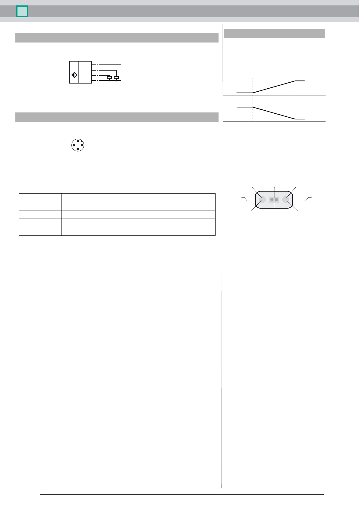
Programmed analogue output function
Analogue function
1)
2)
Near distance
of evaluation
4 mA/
0 V
20 mA/
10 V
Far distance
of evaluation
20 mA/10 V
4 mA/0 V
LED-Window
LED
yellow
E2 E3
Evaluation limit 1
Dual-LED
green/red
A1 A2
"Power on"/Disturbance
LED
yellow
Evaluation limit 2
Description of the TEACH-IN procedure
- Remove temperature plug
- Cut and restore supply voltage (e.g. by removing and replacing unit plug)
TEACH-IN of evaluation limits A1 and A2
- Set object to desired evaluation limit
- Connect TEACH-IN plug in pos. A1 or A2
- Green LED flashes when object detected, red LED flashes when no object detected
- Pull the plug (the current object position is taught and stored when the plug is removed!!)
TEACH-IN of output function
- Connect TEACH-IN plug in pos. E2/E3
- The yellow LED indicates the output function
E2: falling ramp
E3: rising ramp
- Pull the plug when the desired function is activated, otherwise reconnect the TEACH-IN plug in pos.
E2/E3
- Pull plug
Completing the TEACH-IN procedure
- Connect TEACH-IN plug in pos. T. Temperature compensation is now activated.
If the temperature plug has not been plugged in within 5 minutes, the sensor will return to normal mode without temperature compensation.
Default setting
A1: unusable area
A2: nominal sensing range
Mode of operation: rising ramp
LED Displays
Release date: 2013-02-26 15:42 Date of issue: 2013-02-26 035208_eng.xml
2
Subject to reasonable modifications due to technical advances. Copyright Pepperl+Fuchs, Printed in Germany
Pepperl+Fuchs Group • • • •
 Loading...