

Pepperl Fuchs UC4000-30GM-E7R2-V15 Data Sheet
Ultrasonic sensor UC4000-30GM-E7R2-V15
Technical data
General specifications
Sensing range 200 ... 4000 mm
Adjustment range 240 ... 4000 mm
Dead band 0 ... 200 mm
Standard target plate 100 mm x 100 mm
Transducer frequency approx. 85 kHz
Model Number
UC4000-30GM-E7R2-V15
Single head system
Features
• Parameterization interface for the
application-specific adjustment of
the sensor setting via the service
program ULTRA 3000
• 2 programmable switch outputs
• Hysteresis mode selectable
• Window mode selectable
• Synchronization options
• Adjustable acoustic power and
sensitivity
• Temperature compensation
Diagrams
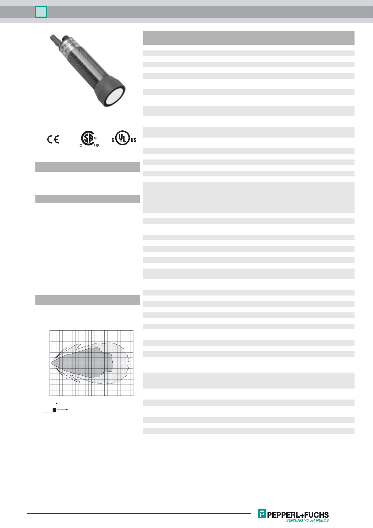
Characteristic response curve
Distance Y [m]
1.5
1.0
0.5
0.0
-0.5
-1.0
-1.5
0,0 0,5 1,0 1,5 2,0 2,5 3,0 3,5 4,0 4,5 5,0 5,5 6,0 6,5
Y
X
Curve 1: flat surface 100 mm x 100 mm
Curve 2: round bar, Ø 25 mm
2
1
Distance X [m]
Response delay 145 ms minimum
Indicators/operating means
LED green solid: Power-on
LED yellow 1 solid: switching state switch output 1
LED yellow 2 solid: switching state switch output 2
LED red solid: temperature/program plug not connected
Temperature/TEACH-IN connector Temperature compensation , Switch points programming ,
Electrical specifications
Operating voltage U
No-load supply current I
Interface
Interface type RS 232, 9600 Bit/s , no parity, 8 data bits, 1 stop bit
Input/Output
Synchronization bi-directional
Synchronization frequency
Common mode operation ≤ 13 Hz
Multiplex operation ≤ 13 Hz / n , n = number of sensors , n ≤ 5
Output
Output type 2 switch outputs NPN, NO/NC, programmable
Rated operating current I
Voltage drop U
Repeat accuracy ≤ 0.1 % of full-scale value
Switching frequency f ≤ 1 Hz
Range hysteresis H 1 % of the adjusted operating range (default settings),
Temperature influence ≤ 2 % from full-scale value (with temperature compensation)
Ambient conditions
Ambient temperature -25 ... 70 °C (-13 ... 158 °F)
Storage temperature -40 ... 85 °C (-40 ... 185 °F)
Mechanical specifications
Connection type Connector M12 x 1 , 5-pin
Degree of protection IP65
Material
Housing stainless steel (1.4305 / AISI 303)
Transducer epoxy resin/hollow glass sphere mixture; polyurethane foam
Mass 180 g
Factory settings
Output 1 Switching point: 500 mm
Output 2 Switching point: 4000 mm
Compliance with standards and
directives
Standard conformity
Standards EN 60947-5-2:2007 + A1:2012
Approvals and certificates
UL approval cULus Listed, General Purpose
CSA approval cCSAus Listed, General Purpose
CCC approval CCC approval / marking not required for products rated ≤36 V
B
0
e
d
440 ms factory setting
flashing: Standby mode or program function object detected
flashing: program function
flashing: program function
flashing: fault or program function object not detected
output function setting
10 ... 30 V DC , ripple 10 %
≤ 50 mA
0 level -U
1 level: +4 V...+U
input impedance: > 12 KOhm
synchronization pulse: ≥ 100 µs, synchronization interpulse
period: ≥ 2 ms
200 mA , short-circuit/overload protected
≤ 2.5 V
programmable
≤ 0.2 %/K (without temperature compensation)
PBT plastic parts
output function: Switch point operation mode
output behavior: NO contact
output function: Switch point operation mode
output behavior: NO contact
IEC 60947-5-2:2007 + A1:2012
...+1 V
B
SS
B
Release date: 2016-04-25 09:35 Date of issue: 2016-04-25 102162_eng.xml
Refer to “General Notes Relating to Pepperl+Fuchs Product Information”.
1
Ultrasonic sensor UC4000-30GM-E7R2-V15
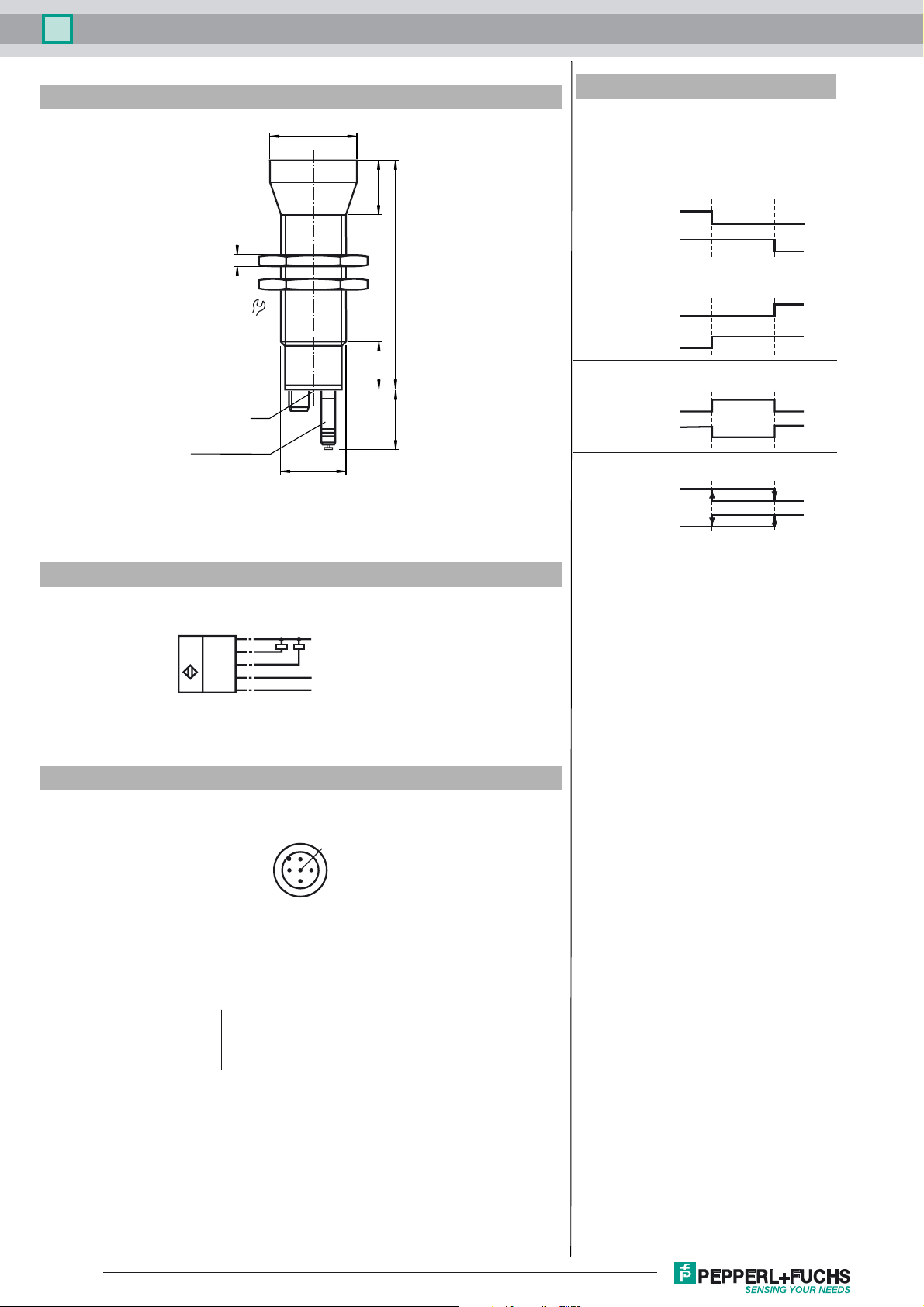
Dimensions
5
36
LED
Temperature probe
Coded plug
ø40
M30x1.5
Additional Information
Possible operating modes
1. Switch point mode
When A1 < A2, both switch outputs are activated as
N. O. co ntac ts.
25
108
22
27.5
A 1 (N.O.)
Switch output 1
A 2 (N.O.)
Switch output 2
When A1 > A2, both switch outputs are activated as
N.C. contacts.
A 1 (N.C.)
Switch output 1
A2 (N.C.)
Switch output 2
2. Window mode
To exchange the switching distances is of no effect.
A 1 (N.O.)
Switch output 1
A2 (N.C.)
Switch output 2
3. Latching mode
To exchange the switching distances is of no effect.
A 1 (N.O.)
Switch output 1
A2 (N.C.)
Switch output 2
Switch point 1
Switch point 2
Electrical Connection
Standard symbol/Connection:
(version E7, npn)
U
Core colors in accordance with EN 60947-5-2.
Pinout
Wire colors in accordance with EN 60947-5-2
1 BN
2 WH
3 BU
4 BK
5 GY
1
(BN)
2
(WH)
(BK)
4
(GY)
5
3
(BU)
2
+ U
+ U
B
B
Switch output 1
Switch output 2
Sync.
- U
- U
B
B
1
5
4
3
(brown)
(white)
(blue)
(black)
(gray)
Release date: 2016-04-25 09:35 Date of issue: 2016-04-25 102162_eng.xml
Refer to “General Notes Relating to Pepperl+Fuchs Product Information”.
2
 Loading...