

Ultrasonic sensor UC2000-30GM-IUR2-T-V15
Technical data
General specifications
Sensing range 80 ... 2000 mm
Adjustment range 120 ... 2000 mm
Dead band 0 ... 80 mm
Standard target plate 100 mm x 100 mm
Transducer frequency approx. 175 kHz
Model Number
UC2000-30GM-IUR2-T-V15
Single head system
Features
• Parameterization interface for the
application-specific adjustment of
the sensor setting via the service
program ULTRA 3000
• Analog current and voltage output
• Synchronization options
• Adjustable acoustic power and
sensitivity
• Temperature compensation
Diagrams
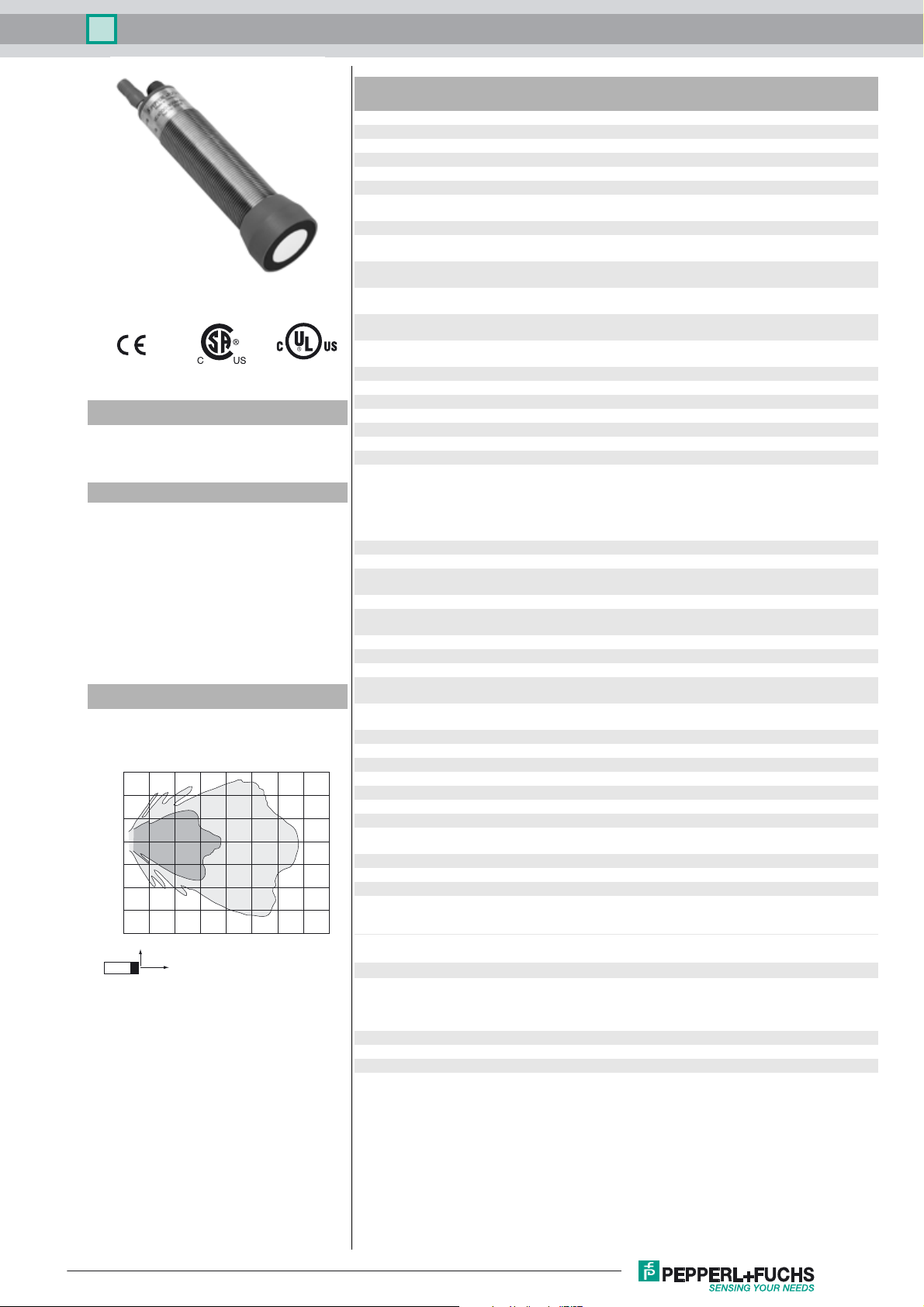
Characteristic response curve
Distance Y [m]
0.6
0.4
0.2
0.0
-0.2
-0.4
-0.6
-0.8
0.0 0.5 1.0 1.5 2.0 2.5 3.0 3.5 4.0
Curve 1: flat surface 100 mm x 100 mm
Curve 2: round bar, Ø 25 mm
2
Y
X
1
Distance X [m]
Response delay 65 ms minimum
Indicators/operating means
LED green solid: Power-on
LED yellow 1 solid: object in evaluation range
LED yellow 2 solid: object in detection range
LED red solid: temperature/program plug not connected
Temperature/TEACH-IN connector Temperature compensation , Evaluation range programming
Electrical specifications
Operating voltage U
Power consumption P
Time delay before availability t
Interface
Interface type RS 232, 9600 Bit/s , no parity, 8 data bits, 1 stop bit
Input/Output
Synchronization bi-directional
Synchronization frequency
Common mode operation ≤ 30 Hz
Multiplex operation ≤ 30 Hz / n , n = number of sensors , n ≤ 5
Output
Output type 1 current output 4 ... 20 mA
Resolution evaluation range [mm]/4000, but ≥ 0.35 mm
Deviation of the characteristic curve ≤ 0.2 % of full-scale value
Repeat accuracy ≤ 0.1 % of full-scale value
Load impedance current output: ≤ 500 Ohm
Temperature influence ≤ 2 % from full-scale value (with temperature compensation)
Ambient conditions
Ambient temperature -25 ... 70 °C (-13 ... 158 °F)
Storage temperature -40 ... 85 °C (-40 ... 185 °F)
Mechanical specifications
Connection type Connector plug M12 x 1 , 5-pin
Degree of protection IP65
Material
Housing stainless steel (1.4305 / AISI 303)
Transducer epoxy resin/hollow glass sphere mixture; polyurethane foam
Mass 210 g
Factory settings
Output evaluation limit A1: 200 mm
Compliance with standards and
directives
Standard conformity
Standards EN 60947-5-2:2007+A1:2012
Approvals and certificates
UL approval cULus Listed, General Purpose
CSA approval cCSAus Listed, General Purpose
CCC approval CCC approval / marking not required for products rated ≤36 V
B
0
v
195 ms factory setting
flashing: Standby mode or program function object detected
flashing: program function
flashing: program function
flashing: fault or program function object not detected
, output function setting
10 ... 30 V DC , ripple 10 %
≤ 900 mW
≤ 500 ms
0 level -U
1 level: +4 V...+U
input impedance: > 12 KOhm
synchronization pulse: ≥ 100 µs, synchronization interpulse
period: ≥ 2 ms
1 voltage output 0 ... 10 V
voltage output: ≥ 1000 Ohm
≤ 0.2 %/K (without temperature compensation)
PBT plastic parts
evaluation limit A2: 2000 mm
rising ramp
IEC 60947-5-2:2007 + A1:2012
EN 60947-5-7:2003
IEC 60947-5-7:2003
...+1 V
B
SS
B
Release date: 2018-01-08 10:27 Date of issue: 2018-01-09 129684_eng.xml
Refer to “General Notes Relating to Pepperl+Fuchs Product Information”.
1
Ultrasonic sensor UC2000-30GM-IUR2-T-V15
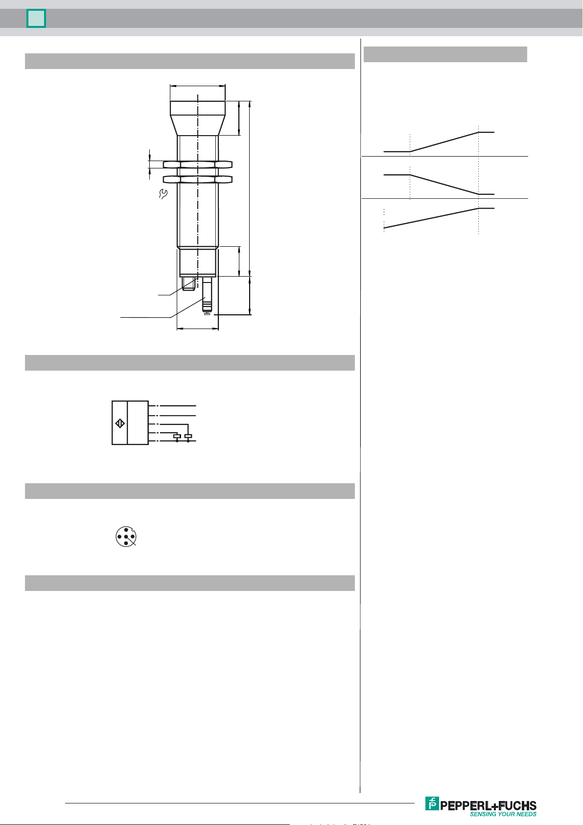
Dimensions
5
36
LED
Temperature probe
Coded plug
ø40
M30x1.5
Additional Information
Analogue output function
Analog function
Near distance
25
of evaluation
Rising slope
4 mA/0 V
Falling slope
20 mA/10 V
128
Zero line mode
4 mA/0 V
A1= 0 mm A2
22
27.5
Far distance
of evaluation
20 mA/10 V
4 mA/0 V
20 mA/10 V
Electrical Connection
Standard symbol/Connection:
(version IU)
1
(BN)
(GY)
U
Core colors in accordance with EN 60947-5-2.
5
2
(WH)
(BK)
4
(BU)
3
Pinout
Connector V15
2
1
3
5
4
Accessories
BF 30
Mounting flange, 30 mm
BF 30-F
Mounting flange with dead stop, 30 mm
UC-30GM-PROG
+ U
B
Sync.
0-10 V
4-20 mA
- U
B
ULTRA3000
Software for ultrasonic sensors, comfort line
UC-30GM-R2
DA5-IU-2K-V
Process control and indication equipment
V15-G-2M-PVC
Female cordset, M12, 5-pin, PVC cable
Description of Sensor Functions
Refer to “General Notes Relating to Pepperl+Fuchs Product Information”.
2
Release date: 2018-01-08 10:27 Date of issue: 2018-01-09 129684_eng.xml

Ultrasonic sensor UC2000-30GM-IUR2-T-V15
Programming procedure
The sensor features 2 programmable analog outputs with programmable evaluation range. Programming the evaluation
range and the operating mode is done either via the sensor's RS232 interface and ULTRA3000 software (see the
ULTRA3000 software description) or by means of the programming plug at the sensor's back end which is described
here.
Programming of Evaluation Range
1. Disconnect supply voltage
2. Remove the programming plug to activate program mode.
3. Reconnect supply voltage (Reset)
4. Place the target at the desired position for A1
5. Momentarily insert the programming plug in position A1 and then remove. This will program the position A1.
6. Place the target at the desired position for A2
7. Momentarily insert the programming plug in position A2 and then remove. This will program the position A2.
Notes:
Coded plug
• Removing the programming plug saves the new position into the device memory.
• The programming status is indicated by the LED. A flashing green LED indicates that the target is detected; a flashing red LED indicates that
no target is detected.
Programming the Operation Mode
If the program mode is still activated, continue at number 4. If not, activate program mode by performing the sequence numbers 1 to 3.
1. Disconnect supply voltage
2. Remove the programming plug to activate program mode.
3. Reconnect supply voltage (Reset)
4. Insert the programming plug in position E2/E3. By removing and reinserting the plug, the user can toggle through the three different modes
of operation. The selected mode is indicated by the LEDs as shown below:
• Rising slope mode, LED A2 flashes
• Falling slope mode, LED A1 flashes
• Zero line mode, LEDs A1 and A2 flash
5. Once the desired mode is selected, insert the programming plug in position T. This completes the programming procedure and saves the
switch points and mode of operation.
6. The sensor now operates in normal mode.
Note:
The programming plug also functions as the temperature compensation. If the programming plug has not been inserted in the T position within 5
minutes, the sensor will return to normal operating mode with the latest saved values, without temperature compensation.
A2
A1
T
E2/E3
Factory settings
See technical data.
Display
The sensor provides LEDs to indicate various conditions.
#
During Normal Operation
- Temperature compensated
- with removed programming plug
Interference (e.g. compressed air)
During Sensor Programming
Evaluation limit A1:
Object detected
No object detected
Evaluation limit A2:
Object detected
No object detected
Operation mode:
Rising slope mode
Falling slope mode
Zero line mode
Standby
LED
yellow
E2 E3
Evaluation limit 1
Dual-LED
green/red
A1 A2
"Power on"/Disturbance
Green LED Red LED Yellow LED A1 Yellow LED A2
On
Off
Off
Flashing
Off
Flashing
Off
On
On
On
Flashing Off remains in previous state remains in previous state
LED
yellow
Evaluation limit 2
Off
On
Flashing
Off
Flashing
Off
Flashing
Off
Off
Off
Object in evaluation range
Object in evaluation range
remains in previous state
Flashing
Flashing
Off
Off
Off
Flashing
Flashing
Object in sensing range
Object in sensing range
remains in previous state
Off
Off
Flashing
Flashing
Flashing
Off
Flashing
Synchronization
This sensor features a synchronization input for suppressing ultrasonic mutual interference ("cross talk"). If this input is not connected, the sensor
will operate using internally generated clock pulses. It can be synchronized by applying an external square wave. The pulse duration must be ≥
100 µs. Each falling edge of the synchronization pulse triggers transmission of a single ultrasonic pulse. If the synchronization signal remains low
for ≥ 1 second, the sensor will revert to normal operating mode. Normal operating mode can also be activated by opening the signal connection
to the synchronization input (see note below).
If the synchronization input goes to a high level for > 1 second, the sensor will switch to standby mode, indicated by the green LED. In this mode,
the outputs will remain in the last valid output state.
Release date: 2018-01-08 10:27 Date of issue: 2018-01-09 129684_eng.xml
Refer to “General Notes Relating to Pepperl+Fuchs Product Information”.
3

Ultrasonic sensor UC2000-30GM-IUR2-T-V15
Note:
If the option for synchronization is not used, the synchronization input has to be connected to ground (0 V) or the sensor must be operated via a
V1 cordset (4-pin).
The synchronization function cannot be activated during programming mode and vice versa.
The following synchronization modes are possible:
1. Several sensors (max. number see technical data) can be synchronized together by interconnecting their respective synchronization inputs.
In this case, each sensor alternately transmits ultrasonic pulses in a self multiplexing mode. No two sensors will transmit pulses at the same
time (see note below).
2. Multiple sensors can be controlled by the same external synchronization signal. In this mode the sensors are triggered in parallel and are synchronized by a common external synchronization pulse.
3. A separate synchronization pulse can be sent to each individual sensor. In this mode the sensors operate in external multiplex mode (see note
below).
4. A high level (+U
Note:
Sensor response times will increase proportionally to the number of sensors that are in the synchronization string. This is a result of the multiplexing of the ultrasonic transmit and receive signal and the resulting increase in the measurement cycle time.
) on the synchronization input switches the sensor to standby mode.
B
Note on communication with the UC-30GM-R2 interface cable
The UC-30GM-R2 interface cable allows for communication with the ultrasonic sensor using
ULTRA3000 software. The cable creates a connection between a PC RS-232 interface and the
programming plug socket on the sensor. When connecting to the sensor, make certain the plug
is lined up correctly; otherwise no communication will be possible. The key of the cable’s plug
must be aligned to the groove of the socket on the sensor (not with the arrow symbol on the sensor).
Programmable parameters with the ULTRA3000 software
Temperature/program
connector
(PC connection via interface cable UC-30GM-R2)
1: TXD
2: RXD
3: not used
4: GND
Groove
4
3
1
2
V15-plug connector
(M12x1)
LED-window
• Evaluation limits A1 and A2
•Operation mode
• Sonic speed
• Temperature offset (The inherent temperature-rise of the sensor can be considered in the temperature compensation)
• Expansion of the unusable area (for suppression of unusable area echoes)
• Reduction of the detection range (for suppression of remote range echoes)
• Time of measuring cycle
• Acoustic power (interference of the burst duration)
• Sensitivity
• Behavior of the sensor in case of echo loss
• Behavior of the sensor in case of a fault
• Average formation via an allowed number of measuring cycles
• Selection of the parameter set, RS 232 or manually
Note:
When connected to a PC and running the ULTRA3000 software, the sensor can act as a long term data logger as well.
Installation conditions
If the sensor is installed in an environment where the temperature can fall below 0 °C, one of these mounting flanges must be used for mounting:
BF30, BF30-F, or BF 5-30.
If the sensor is mounted in a through hole using the included steel nuts, it must be mounted at the middle of the threaded housing. If it must be
mounted at the front end of the threaded housing, plastic nuts with centering ring (optional accessories) must be used.
Release date: 2018-01-08 10:27 Date of issue: 2018-01-09 129684_eng.xml
Refer to “General Notes Relating to Pepperl+Fuchs Product Information”.
4
 Loading...