

Ultrasonic sensor UC2000-30GM-2EP-IO-V15
Model Number
UC2000-30GM-2EP-IO-V15
Single head system
Features
• IO-link interface for service and
process data
• Programmable via DTM with
PACTWARE
• 2 programmable switch outputs
• Selectable sound lobe width
• Synchronization options
• Temperature compensation
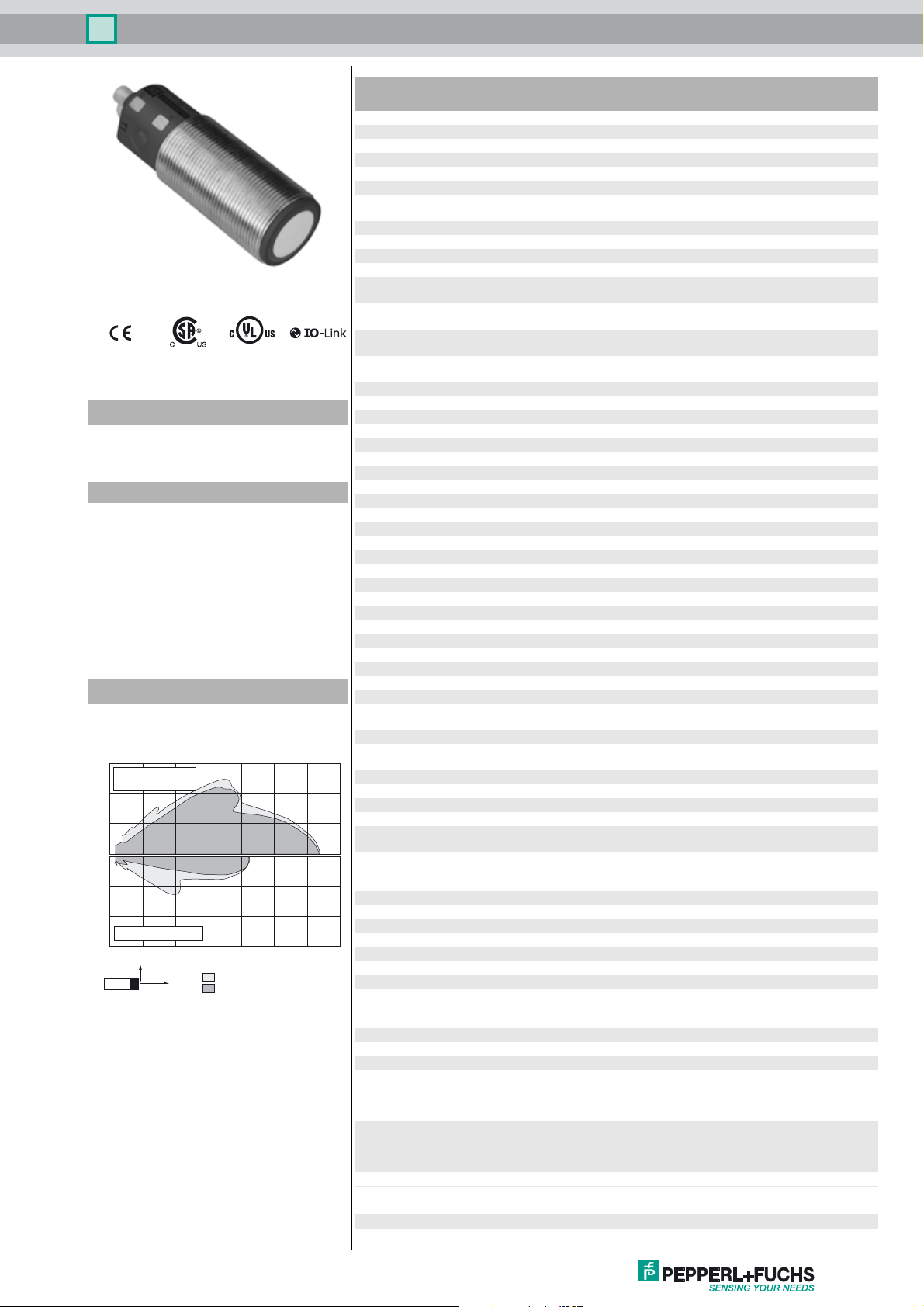
Diagrams
Characteristic response curve
Distance Y [mm]
600
flat surface
100 mm x 100 mm
400
200
0
-200
-400
round bar, Ø 25 mm
-600
0 500 1000 1500 2000 2500 3000 3500
Y
Release date: 2017-10-24 12:01 Date of issue: 2017-10-27 191243_eng.xml
Refer to “General Notes Relating to Pepperl+Fuchs Product Information”.
X
wide sound lobe
narrow sound lobe
Distance X [mm]
Technical data
General specifications
Sensing range 90 ... 2000 mm
Adjustment range 120 ... 2000 mm
Dead band 0 ... 90 mm
Standard target plate 100 mm x 100 mm
Transducer frequency approx. 200 kHz
Response delay minimum : 65 ms
Memory
Non-volatile memory EEPROM
Write cycles 100000
Indicators/operating means
LED green solid: Power on
LED yellow 1 solid: Object in evaluation range
LED yellow 2 solid: Object in evaluation range
LED red solid red: Error
Electrical specifications
Operating voltage U
No-load supply current I
Power consumption P
Time delay before availability t
Interface
Interface type IO-Link
Protocol IO-Link V1.0
Transfer rate Acyclical: typical 95 Bit/s
Cycle time min. 33.6 ms
Mode COM 2 (38.4 kBaud)
Process data witdh 16 bit
SIO mode support yes
Input/Output
Input/output type 1 synchronization connection, bidirectional
0 Level 0 ... 1 V
1 Level 4 V ... U
Input impedance > 12 kΩ
Output rated operating current < 12 mA
Pulse length 0.5 ... 300 ms (level 1)
Pulse interval ≥ 33 ms (level 0)
Synchronization frequency
Common mode operation ≤ 30 Hz
Multiplex operation ≤ 33 Hz / n , n = number of sensors , n ≤ 10
Output
Output type 2 push-pull (4 in 1) outputs, short-circuit protected, reverse
Rated operating current I
Voltage drop U
Repeat accuracy ≤ 0.1 % of full-scale value
Switching frequency f ≤ 4 Hz
Range hysteresis H 1 % of the adjusted operating range (default settings),
Temperature influence ≤ 1.5 % from full-scale value (with temperature
Ambient conditions
Ambient temperature -25 ... 70 °C (-13 ... 158 °F)
Storage temperature -40 ... 85 °C (-40 ... 185 °F)
Mechanical specifications
Connection type Connector plug M12 x 1 , 5-pin
Degree of protection IP67
Material
Housing Stainless steel 1.4305 / AISI 303
Transducer epoxy resin/hollow glass sphere mixture; polyurethane foam
Mass 72 g
Factory settings
Output 1 near switch point: 120 mm
Output 2 near switch point: 120 mm
Beam width wide
Compliance with standards and
directives
Standard conformity
B
0
0
v
e
d
factory setting: 125 ms
flashing: Standby mode or IO link communication
flashing: Learning function, object detected
flashing: Learning function, object detected
red, flashing: program function, object not detected
10 ... 30 V DC , ripple 10 %
≤ 60 mA
≤ 1 W
≤ 120 ms
B
(factory setting: n = 5 )
polarity protected
200 mA , short-circuit/overload protected
≤ 2.5 V
programmable
compensation)
≤ 0.2 %/K (without temperature compensation)
TPU
Polyamides
far switch point: 2000 mm
output function: Window mode
output behavior: NO contact
far switch point: 1000 mm
output function: Window mode
output behavior: NO contact
SS
1
Ultrasonic sensor UC2000-30GM-2EP-IO-V15
Standards EN 60947-5-2:2007+A1:2012
Approvals and certificates
UL approval cULus Listed, General Purpose
CSA approval cCSAus Listed, General Purpose
CCC approval CCC approval / marking not required for products rated ≤36 V
IEC 60947-5-2:2007 + A1:2012
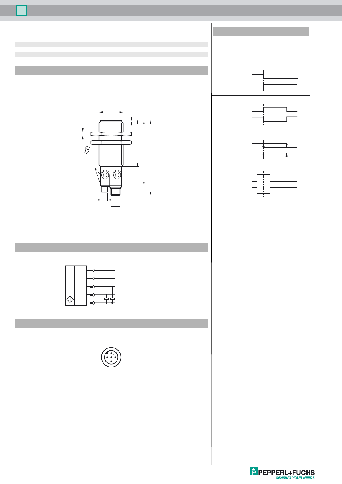
Dimensions
M30 x 1.5
2
5
56
36
LED
T1 T2
ø7
M12
81
93
Additional Information
Switching output operating modes
1. Switching point mode
NO contact
NC contact
2. Window mode
NO contact
NC contact
3. Hysteresis mode
NO contact
NC contact
4. Retroreflective sensor mode
NO contact
NC contact
Near
switching
point
Far
switching
point
Electrical Connection
Pinout
Wire colors in accordance with EN 60947-5-2
1 BN
2 WH
3 BU
4 BK
5 GY
1
5
4
2
3
2
L+
1
3
(brown)
(white)
(blue)
(black)
(gray)
Sync.
C/Q
Switch output 2
L-
5
4
Release date: 2017-10-24 12:01 Date of issue: 2017-10-27 191243_eng.xml
Refer to “General Notes Relating to Pepperl+Fuchs Product Information”.
2
 Loading...