

Pepperl Fuchs UC10000-F260-IE8R2-Y250792 Data Sheet
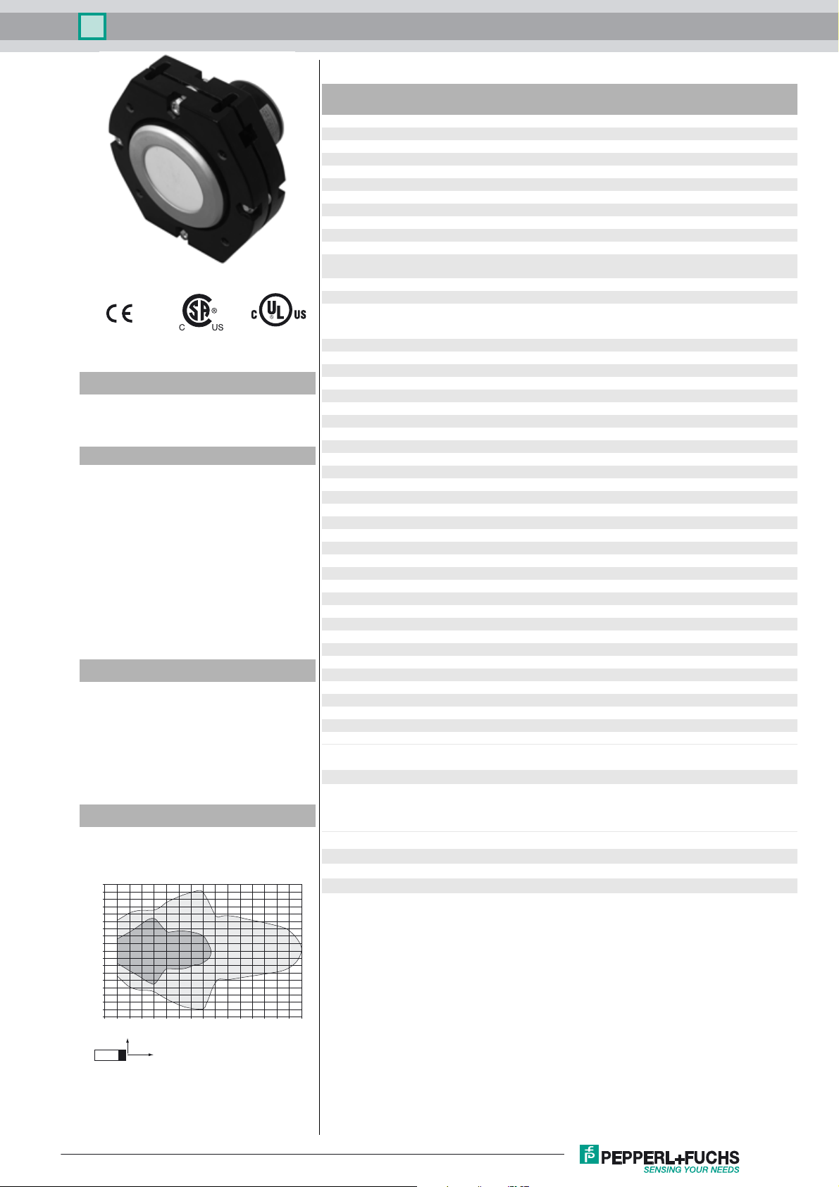
Ultrasonic sensor UC10000-F260-IE8R2-Y250792
Technical data
General specifications
Sensing range 800 ... 10000 mm
Adjustment range 800 ... 10000 mm
Dead band 0 ... 800 mm
Standard target plate 100 mm x 100 mm
Transducer frequency approx. 60 kHz
Nominal ratings
Model Number
UC10000-F260-IE8R2-Y250792
Single head system
Features
• Large sensing range
• Adjustable Bracket
• Programmable by means of Interface (see accessories) and SONPROG
• 1 analog output, 0-20 mA current
source
•2 switch outputs
• Synchronization options
• Temperature compensation
Description
This ultrasonic sensor is a contactless distance sensor
based on the echo run time principle. It is suitable for
the detection of solid, liquid or powder sound-reflecting
objects. The unique sensor design allows easy movement of the direction of sound radiation in all spatial directions by up to 10° without additional an additional
assembly device.
Diagrams
Time delay before availability t
Limit data
v
Permissible cable length max. 300 m
Indicators/operating means
LED yellow solid: switching state switch output
Electrical specifications
Rated operating voltage U
Operating voltage U
e
B
Ripple ≤ 10 %
No-load supply current I
Input/Output
0
Input/output type 1 synchronization connection, bidirectional
0 Level ≤ 3 V
1 Level 15 ... 30 V
Input impedance typ. 0.9 kΩ
Number of sensors max. 10
Switching output
Output type 2 switch outputs PNP, NO
Repeat accuracy R ± 15 mm
Operating current I
Voltage drop ≤ 3 V
L
Switch-on delay 800 ms
Analog output
Output type 1 current output 0 ... 20 mA rising ramp
Default setting 800 ... 10000 mm
Linearity error ≤ 1.5 %
Load resistor ≤ 300 Ω
Ambient conditions
Ambient temperature -25 ... 70 °C (-13 ... 158 °F)
Storage temperature -40 ... 85 °C (-40 ... 185 °F)
Shock resistance 30 g , 11 ms period
Vibration resistance 10 ... 55 Hz , Amplitude ± 1 mm
Mechanical specifications
Connection type screw terminals , PG 13.5 cable gland
Degree of protection IP65
Material
Housing UP 1225 SF/R8
Transducer epoxy resin/hollow glass sphere mixture; polyurethane foam
Installation position any position
Mass 1800 g
Compliance with standards and
directives
Standard conformity
Standards EN 60947-5-2:2007 + A1:2012
280 ms
flashing: misadjustment
24 V DC
15 ... 30 V (including ripple)
In supply voltage interval 15 ... 20 V sensitivity reduced to
20% ... 0%
≤ 75 mA
300 mA , short-circuit/overload protected
IEC 60947-5-2:2007 + A1:2012
EN 60947-5-7:2003
IEC 60947-5-7:2003
Characteristic response curve
Distance Y [mm]
1800
1600
1400
1200
1000
800
600
400
200
0
-200
-400
-600
-800
-1000
-1200
-1400
-1600
-1800
0 2000 4000 6000 8000 10000 12000 14000 16000
Y
Curve 1: flat surface 100 mm x 100 mm
Curve 2: round bar, Ø 25 mm
Release date: 2016-02-16 08:15 Date of issue: 2016-02-16 250792_eng.xml
Refer to “General Notes Relating to Pepperl+Fuchs Product Information”.
2
X
1
Distance X [mm]
Approvals and certificates
UL approval cULus Listed, General Purpose
CSA approval cCSAus Listed, General Purpose
CCC approval CCC approval / marking not required for products rated
≤36 V
1
Ultrasonic sensor UC10000-F260-IE8R2-Y250792
Dimensions
112
ø 8.5
160
97.6
160
Additional Information
Area definitions
S
AE
min
Blind
area
Analog output
4 mA
0 mA/0 V
Sensing range
S
max
ca. 5°
20 mA
10 V
Electrical Connection
L+
XI
I
A/UA
S
SX
GND
+U
B
Input
Analog output
Switch output 1
Switch output 2
-U
B
Accessories
DA5-IU-C
Digital display unit
3RX4000-PF
PC interface
V15S-G-2M-PVC
Cable connector, M12, 5-pin, PVC cable
V1-M20-80
Receptacles, M12/M20; plastic version
Danger!
This product must not be used in applications in which the safety of persons depends on the device
function.
This product is not a safety component in accordance with the EU Machinery Directive.
Assembly and connection
When installing the sensor, make sure that the space filled by the sound
cone is free from interfering objects. Objects in the blind zone cause
cause false signals. Implement suitable measures to ensure that objects
cannot enter the blind zone.
The electrical connection is made via screw terminals. The connections
are protected against reverse polarity, short circuits and overloads.
Shielded cables are recommended if there is electrical interference.
Setting
The detection range limits S
Within these limits, the switch points A and E are set using a potentiom-
min
and S
are fixed (see Technical data).
max
eter. Switch point A must be smaller than switch point E. If this is not the
case, the LED flashes and correct switching is not possible.
Refer to “General Notes Relating to Pepperl+Fuchs Product Information”.
2
LED P1(A)
GND L+
A
/U
A
I
P2(E)
XI
NO/NC
SX S
NO/NC
Release date: 2016-02-16 08:15 Date of issue: 2016-02-16 250792_eng.xml
 Loading...