


Ultrasonic sensor UC10000-F260-IE8R2
Technical data
General specifications
Sensing range 800 ... 10000 mm
Adjustment range 800 ... 10000 mm
Dead band 0 ... 800 mm
Standard target plate 100 mm x 100 mm
Transducer frequency approx. 60 kHz
Nominal ratings
Model Number
UC10000-F260-IE8R2
Single head system
Features
• Large sensing range
• Adjustable Bracket
• Programmable by means of Interface (see accessories) and SONPROG
• Analog output 4 ... 20 mA
•2 switch outputs
• Synchronization options
• Temperature compensation
Description
This ultrasonic sensor is a contactless distance sensor
based on the echo run time principle. It is suitable for
the detection of solid, liquid or powder sound-reflecting
objects. The unique sensor design allows easy movement of the direction of sound radiation in all spatial directions by up to 10° without additional an additional
assembly device.
Diagrams
Characteristic response curve
Distance Y [mm]
1800
1600
1400
1200
1000
800
600
400
200
0
-200
-400
-600
-800
-1000
-1200
-1400
-1600
-1800
0 2000 4000 6000 8000 10000 12000 14000 16000
Y
2
X
1
Distance X [mm]
Time delay before availability t
Limit data
v
Permissible cable length max. 300 m
Indicators/operating means
LED yellow solid: switching state switch output
Electrical specifications
Rated operating voltage U
Operating voltage U
e
B
Ripple ≤ 10 %
No-load supply current I
Input/Output
0
Input/output type 1 synchronization connection, bidirectional
0 Level ≤ 3 V
1 Level 15 ... 30 V
Input impedance typ. 0.9 kΩ
Number of sensors max. 10
Switching output
Output type 2 switch outputs PNP, NO
Repeat accuracy R ± 15 mm
Operating current I
Voltage drop ≤ 3 V
L
Switch-on delay 800 ms
Analog output
Output type 1 current output 4 ... 20 mA rising ramp
Default setting 800 ... 10000 mm
Linearity error ≤ 1.5 %
Load resistor ≤ 300 Ω
Ambient conditions
Ambient temperature -25 ... 70 °C (-13 ... 158 °F)
Storage temperature -40 ... 85 °C (-40 ... 185 °F)
Shock resistance 30 g , 11 ms period
Vibration resistance 10 ... 55 Hz , Amplitude ± 1 mm
Mechanical specifications
Connection type screw terminals , PG 13.5 cable gland
Degree of protection IP65
Material
Housing UP 1225 SF/R8
Transducer epoxy resin/hollow glass sphere mixture; polyurethane foam
Installation position any position
Mass 1800 g
Compliance with standards and
directives
Standard conformity
Standards EN 60947-5-2:2007 + A1:2012
Approvals and certificates
UL approval cULus Listed, General Purpose
CSA approval cCSAus Listed, General Purpose
CCC approval CCC approval / marking not required for products rated
280 ms
flashing: misadjustment
24 V DC
15 ... 30 V (including ripple)
In supply voltage interval 15 ... 20 V sensitivity reduced to
20% ... 0%
≤ 75 mA
300 mA , short-circuit/overload protected
IEC 60947-5-2:2007 + A1:2012
EN 60947-5-7:2003
IEC 60947-5-7:2003
≤36 V
Curve 1: flat surface 100 mm x 100 mm
Curve 2: round bar, Ø 25 mm
Release date: 2016-02-16 08:15 Date of issue: 2016-02-16 250790_eng.xml
Refer to “General Notes Relating to Pepperl+Fuchs Product Information”.
1
Ultrasonic sensor UC10000-F260-IE8R2
Dimensions
112
ø 8.5
160
97.6
160
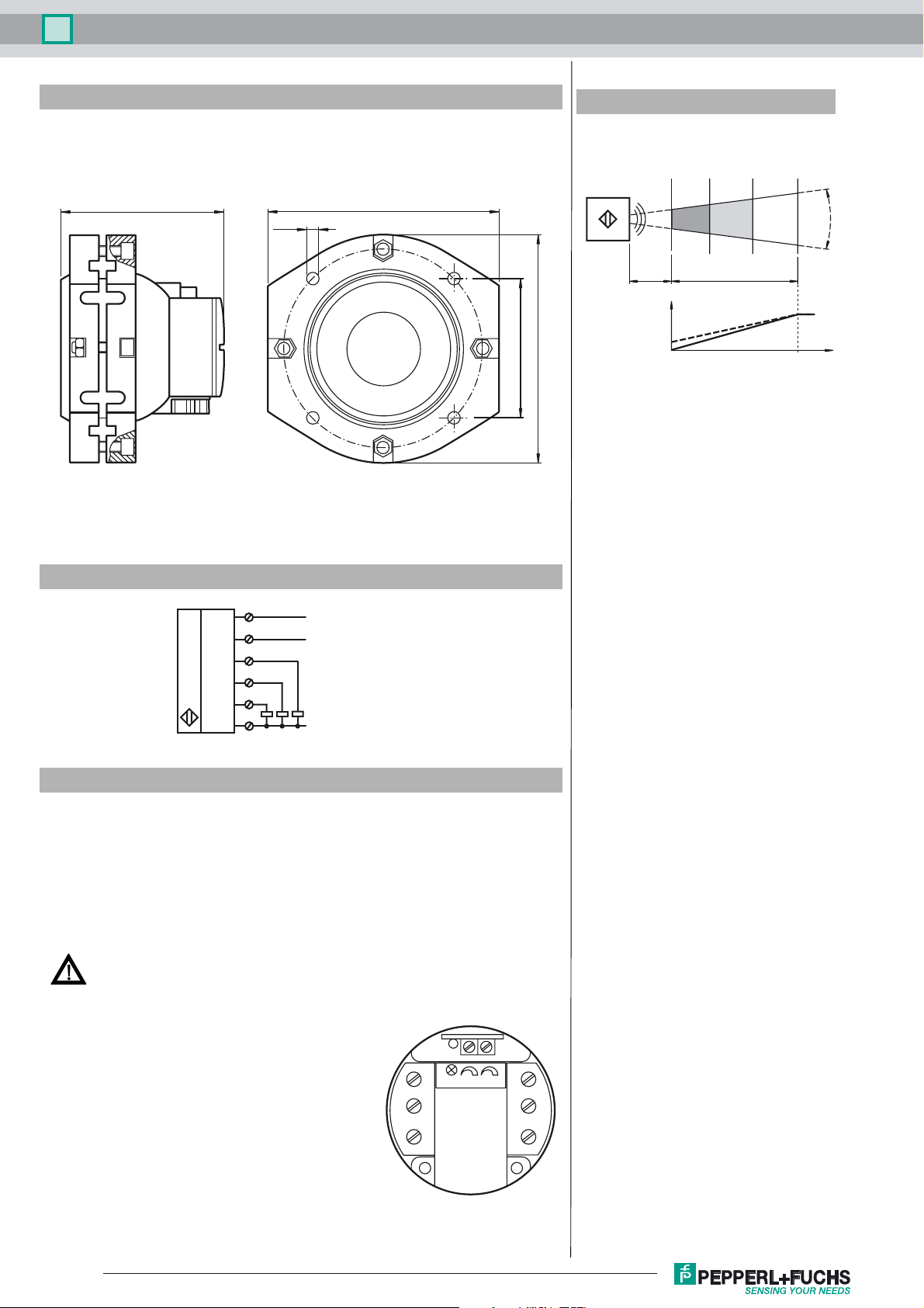
Additional Information
Area definitions
S
AE
min
Blind
area
Analog output
4 mA
0 mA/0 V
Sensing range
S
max
ca. 5°
20 mA
10 V
Electrical Connection
L+
XI
I
A/UA
S
SX
GND
+U
B
Input
Analog output
Switch output 1
Switch output 2
-U
B
Accessories
DA5-IU-C
Digital display unit
3RX4000-PF
PC interface
V15S-G-2M-PVC
Cable connector, M12, 5-pin, PVC cable
V1-M20-80
Receptacles, M12/M20; plastic version
Danger!
This product must not be used in applications in which the safety of persons depends on the device
function.
This product is not a safety component in accordance with the EU Machinery Directive.
Assembly and connection
When installing the sensor, make sure that the space filled by the sound
cone is free from interfering objects. Objects in the blind zone cause
cause false signals. Implement suitable measures to ensure that objects
cannot enter the blind zone.
The electrical connection is made via screw terminals. The connections
are protected against reverse polarity, short circuits and overloads.
Shielded cables are recommended if there is electrical interference.
Setting
The detection range limits S
Within these limits, the switch points A and E are set using a potentiom-
min
and S
are fixed (see Technical data).
max
eter. Switch point A must be smaller than switch point E. If this is not the
case, the LED flashes and correct switching is not possible.
Refer to “General Notes Relating to Pepperl+Fuchs Product Information”.
2
LED P1(A)
GND L+
A
/U
A
I
P2(E)
XI
NO/NC
SX S
NO/NC
Release date: 2016-02-16 08:15 Date of issue: 2016-02-16 250790_eng.xml

Ultrasonic sensor UC10000-F260-IE8R2
Parameterisation via SONPROG
The following parameters can be changed via the SONPROG parameterisation software:
• Measuring range limits S
• Switch-on and switch-off points E and A
• Blind zone
• Averaging
• Analogue limits
• Analogue characteristic, rising/falling
Operation
Within the detection range, which is restricted by the detection range limits S
maximum inclination of 3° to the direction of sound propagation. With rough, uneven surfaces the angular deviation can be bigger. The actual value depends signficantly on
the object finish and should be obtained experimentally if necessary.
Behaviour of the switch outputs:
• If the object is at a distance > E, both switch outputs are in standby mode.
• If the object is between E and A, switch output S is activated and switch output SX is in standby mode.
• If the object is at a distance < A, switch output SX is activated and switch output S is in standby mode.
Behaviour of the analogue output:
The object distance between the detection range limits (S
its minimum value at distance S
output retains its maximum value.
Display:
The sensor has an LED. It lights up continuously when the output terminal S is carrying a voltage. It flashes when switch points A and E are set incorrectly (see Setting).
Function input XI
The sensor is placed in standby mode by connecting a low level at the function input XI (blocked release). The sensors then performs no measurements. The switch outputs
retain the most recent status. As soon as function input XI is disconnected from the low level or a high level is connected (release), the sensor resumes its normal function
after the release period has expired.
The function input XI can be used during operation for the synchronisation of multiple sensors in the event of mutual interefence. The following synchronisation modes are
possible:
• Triggering of each individual sensor with a separate control signal, e.g. by a PLC (external synchronisation).
• Connection of the function inputs XI of all sensors and joint triggering with an external control signal, e.g. by a PLC (external synchronisation, common-mode operation).
• Connection of the function inputs XI of all sensors and without triggering with an external signal (internal synchronisation, multiplex mode).
Maintenance
The ultrasonic sensor is maintenance-free. However, the converter surface must not be wet, damaged, painted or covered with material deposits..
and S
min
max
, S
and its maximum value at distance S
min
min
and S
min
) are displayed in the form of an analogue output signal at the analogue output. The analogue output delivers
max
. The characteristic between the two measuring range limits is linear. Outside of S
max
, the object distance is detected. Objects with an even, smooth surface can have a
max
the analogue
max
Connecting the PC interface 3RX4000-PF to use SONPROG
This sensor can be parameterised using SONPROG for an optimum adaptation to the application. Therefore the sensor provides communication
with the 3RX4000-PF PC interface. To connect to the 3RX4000-PF PC interface a 4- or 5-pin M12 male cable connector is reqired. We recommend e. g. an adapter V1-M20-80 or a cable connector V15S-G-2M-PVC.
Please connect the wires to the sensors terminals as shown, below.
braun BN
blau BU
grau GY
(optional)
The terminals I
P2(E)
XI
SX S
LED P1(A)
GND L+
A
/U
A
I
(analog output) and SX (2nd switching output) are not needed for programming.
A/UA
weiß WH
schwarz BK
NO/NC
NO/NC
Release date: 2016-02-16 08:15 Date of issue: 2016-02-16 250790_eng.xml
Refer to “General Notes Relating to Pepperl+Fuchs Product Information”.
3
 Loading...