

Through-beam ultrasonic barrier UBEC300-18GH40-SE2-V1
Technical data
General specifications
Sensing range 100 ... 300 mm
Standard target plate 100 mm x 100 mm
Transducer frequency approx. 255 kHz
Electrical specifications
Model Number
UBEC300-18GH40-SE2-V1
Features
•Short design, 40mm
• Stainless steel housing
•Chemical-resistant
• Switch output
•Program input
Diagrams
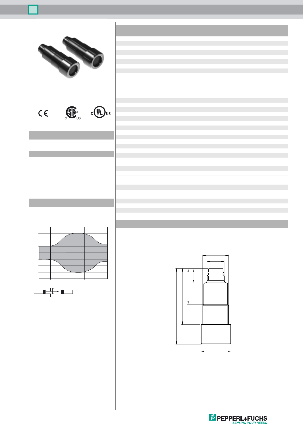
Characteristic response curve
Distance Y [mm]
20
15
10
5
0
-5
-10
-15
-20
0 50 100 150 200 250 300
Distance X [mm]
X
Obstacle: flat plate 100 mm x 100 mm
Y
Operating voltage U
No-load supply current I
Input
Input type 1 program input [receiver]
Output
Output type PNP, NO
Rated operating current I
Voltage drop U
Switch-on delay t
Switching frequency f ≤ 100 Hz
Ambient conditions
Ambient temperature -25 ... 70 °C (-13 ... 158 °F)
Storage temperature -40 ... 85 °C (-40 ... 185 °F)
Mechanical specifications
Connection type Connector M12 x 1 , 4-pin
Degree of protection IP68 / IP69K
Material
Housing Stainless steel 1.4435 / AISI 316L
Transducer PTFE (diaphragm surface)
Mass 25 g
Compliance with standards and
directives
Standard conformity
Standards EN 60947-5-2:2007 + A1:2012
Approvals and certificates
UL approval cULus Listed, General Purpose
CSA approval cCSAus Listed, General Purpose
CCC approval CCC approval / marking not required for products rated ≤36 V
B
0
e
d
on
Dimensions
53
10 ... 30 V DC , ripple 10 %
≤ 20 mA
switch point 1: -U
input impedance: > 4.7 kΩ pulse duration: ≥ 1 s
1 test input [emitter]
emitter deactivated: +6 V ... +U
input impedance: > 4.7 kΩ
200 mA , short-circuit/overload protected
≤ 3 V
< 5 ms
O-ring for cover sealing: EPDM
IEC 60947-5-2:2007 + A1:2012
M18 x 1
M12 x 1
10
25
40
SS
... +1 V, switch point 2: +6 V ... +UB
B
B
Release date: 2016-04-18 10:44 Date of issue: 2016-04-18 211977_eng.xml
Refer to “General Notes Relating to Pepperl+Fuchs Product Information”.
ø 21
1
Through-beam ultrasonic barrier UBEC300-18GH40-SE2-V1
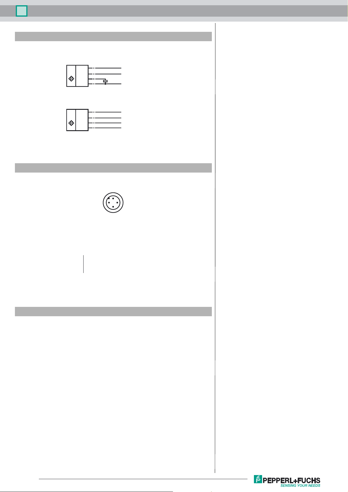
Electrical Connection
Standard symbol/Connection:
(version E2, pnp)
Receiver:
(BN)
Pinout
1
(WH)
U
Emitter:
U
Core colours in accordance with EN 60947-5-2.
2
4
(BK)
(BU)
3
(BN)
1
(WH)
2
(BK)
4
3
(BU)
+U
B
Teaching input
Switching output
-U
B
+U
B
Test input
n.c.
-U
B
Wire colors in accordance with EN 60947-5-2
1 BN
2 WH
3 BU
4 BK
Accessories
UB-PROG2
Programming unit
V1-GV4A-2M-PVC
Female cordset, M12, Stainless steel
V1-WV4A-2M-PVC
Female cordset, M12, Stainless steel
2
1
4
3
(brown)
(white)
(blue)
(black)
Function
A through-beam ultrasonic barrier always consists of a single emitter and a single
receiver. The function of a through-beam ultrasonic barrier is based in the interruption of the sound transmission to the receiver by the object to be detected.
The emitter sends an ultrasonic signal that is evaluated by the receiver. If the signal
is interrupted or muted by the object to be detected, the receiver switches.
No electrical connections are required between the emitter and receiver.
The function of through-beam ultrasonic barriers is not dependent on the position of
their installation. We recommend, however, to install the emitter below in the case
of vertical installations to prevent the accumulation of dust particles.
Startup and parameterising
In the delivery status, the receiver is pr-configured for a 300 mm spacing between
emitter and receiver. If the through-beam ultrasonic barrier is operated at different
spacing, a TEACH-IN procedure has to be carried out.
TEACH-IN
Refer to “General Notes Relating to Pepperl+Fuchs Product Information”.
2
Release date: 2016-04-18 10:44 Date of issue: 2016-04-18 211977_eng.xml

Through-beam ultrasonic barrier UBEC300-18GH40-SE2-V1
1. Install both, emitter and receiver of the through-beam ultrasonic barrier at the desired positions.
2. Adust both devices exactly to each other and fix the adjustment.
3. Remove all obstacles from between the emitter and the receiver.
4. Connect the TEACH input of the receiver with -U
The receiver evaluates now the signal strength of the clear air path.
5. Place the object to be detected at the desired position between emitter and receiver.
6. Connect the TEACH input of the receiver with +U
The receiver evaluates the siognal stength of the attenuated air path and determines the optimal switching threshold. This
switching threshold is then stored into the non-volatile memory of the receiver.
7. Disconnect the TEACH input from +U
.
B
for at least 2 s.
B
for at least 2 s.
B
Release date: 2016-04-18 10:44 Date of issue: 2016-04-18 211977_eng.xml
Refer to “General Notes Relating to Pepperl+Fuchs Product Information”.
3
 Loading...