

Pepperl Fuchs UBE500-18GM40A-V1-Y220367 Data Sheet
Ultrasonic sensor, transmitter UBE500-18GM40A-V1-Y220367
Technical data
General specifications
Sensing range 100 ... 500 mm
Standard target plate 100 mm x 100 mm
Transducer frequency approx. 390 kHz
Indicators/operating means
LED green Power on
LED red Emitter deactivated
Electrical specifications
Model Number
UBE500-18GM40A-V1-Y220367
Single head system
Features
•Short design, 40mm
• Function indicators visible from all
directions
• Test input
• Stainless steel housing
Operating voltage U
No-load supply current I
Input
Input type 1 Test input
Ambient conditions
Ambient temperature -25 ... 70 °C (-13 ... 158 °F)
Storage temperature -40 ... 85 °C (-40 ... 185 °F)
Mechanical specifications
Connection type Connector M12 x 1 , 4-pin
Degree of protection IP67
Material
Housing stainless steel V4A
Transducer epoxy resin/hollow glass sphere mixture; foam polyurethane,
Mass 25 g
Compliance with standards and
directives
Standard conformity
Standards EN 60947-5-2:2007 + A1:2012
Approvals and certificates
UL approval cULus Listed, General Purpose
CSA approval cCSAus Listed, General Purpose
CCC approval CCC approval / marking not required for products rated ≤36 V
B
0
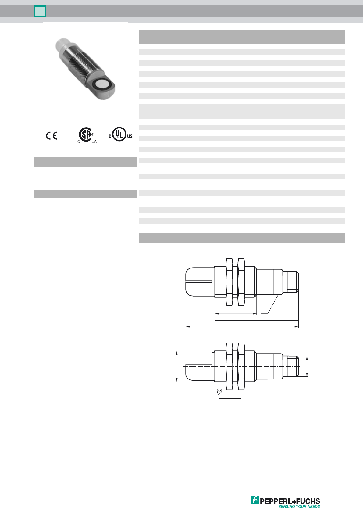
Dimensions
10 ... 30 V DC , ripple 10 %
≤ 20 mA
emitter deactivated: +6 V ... +U
input impedance: > 4.7 kΩ
cover PBT
IEC 60947-5-2:2007 + A1:2012
SS
B
M18 x 1
39.2
LED
10
M12 x 1
24.5
67.7
24
4
Release date: 2016-04-18 10:43 Date of issue: 2016-04-18 220367_eng.xml
Refer to “General Notes Relating to Pepperl+Fuchs Product Information”.
1
Ultrasonic sensor, transmitter UBE500-18GM40A-V1-Y220367
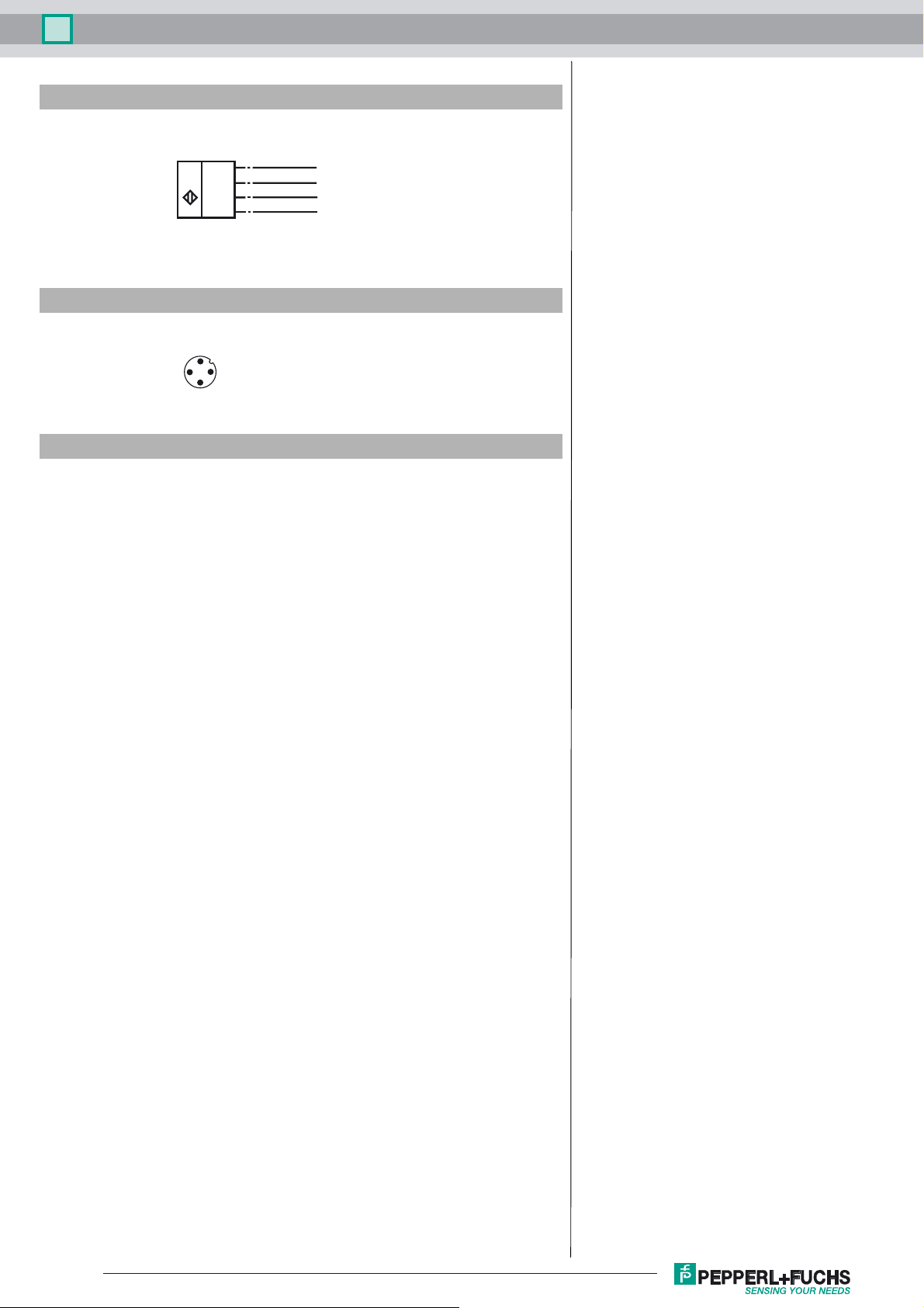
Electrical Connection
Standard symbol/Connections:
(Emitter)
1 (BN)
U
Core colours in accordance with EN 60947-5-2.
2 (WH)
4 (BK)
3 (BU)
Pinout
Connector V1
2
1
3
4
Accessories
CPZ18B03
Mounting Bracket with swivel nut
OMH-04
Mounting aid for round steel ø 12 mm or sheet 1.5 mm ... 3 mm
BF 18
Mounting flange, 18 mm
BF 18-F
Mounting flange with dead stop, 18 mm
BF 5-30
Universal mounting bracket for cylindrical sensors with a diameter of 5 ... 30 mm
V1-G-2M-PVC
Female cordset, M12, 4-pin, PVC cable
V1-W-2M-PUR
Female cordset, M12, 4-pin, PUR cable
+ U
B
Test input
n. c.
- U
B
Function
A through-beam ultrasonic barrier always consists of a single emitter and a single
receiver. The function of a through-beam ultrasonic barrier is based in the interruption of the sound transmission to the receiver by the object to be detected.
The emitter sends an ultrasonic signal that is evaluated by the receiver. If the signal
is interrupted or muted by the object to be detected, the receiver switches.
No electrical connections are required between the emitter and receiver.
The function of through-beam ultrasonic barriers is not dependent on the position of
their installation. We recommend, however, to install the emitter below in the case
of vertical installations to prevent the accumulation of dust particles.
Test function
For test purpose, the ultrasonic emitter is equipped with a test input. In normal operation mode (test input not connected or connected to -U
), the green LED of the
B
emitter is on. If the test input is connected to +UB , the ultrasonic emitter gets deactivated and its LED changes into red. Simultaneously the receiver switches and its
yellow LED goes on.
Release date: 2016-04-18 10:43 Date of issue: 2016-04-18 220367_eng.xml
Refer to “General Notes Relating to Pepperl+Fuchs Product Information”.
2
 Loading...