

Pepperl Fuchs UBE4000-30GM-SA2-V15 Data Sheet
Through-beam ultrasonic barrier UBE4000-30GM-SA2-V15
Technical data
General specifications
Sensing range 0 ... 4000 mm , distance emitter-receiver 500 mm ... 4000 mm
Through-beam mode Single path ultrasonic switch
Reference target receiver
Transducer frequency 85 kHz
Indicators/operating means
Model Number
UBE4000-30GM-SA2-V15
Features
• Reliable detection of transparent
materials
• High switching frequency
• Adjustable sensitivity
• Adjustable switch-on delay
•Small angle of divergence
•Protective functions
• Emitter and receiver included in
the delivery package
LED green alignment aid
LED yellow switching state
Electrical specifications
Operating voltage U
No-load supply current I
B
0
Output
Output type 2 switch outputs PNP, normally open/closed
Rated operating current I
Voltage drop U
Switch-on delay t
d
Switching frequency f ≤ 15 Hz
e
on
Ambient conditions
Ambient temperature 0 ... 60 °C (32 ... 140 °F)
Storage temperature -40 ... 85 °C (-40 ... 185 °F)
Mechanical specifications
Connection type Connector M12 x 1 , 5-pin
Degree of protection IP65
Material
Housing nickel plated brass; plastic components: PBT
Mass 160 g each sensor
Compliance with standards and
directives
Standard conformity
Standards EN 60947-5-2:2007 + A1:2012
Approvals and certificates
UL approval cULus Listed, General Purpose
CSA approval cCSAus Listed, General Purpose
CCC approval CCC approval / marking not required for products rated ≤36 V
OFF: no ultrasonic signal
flashing: uncertain area
ON: positive reception
18 ... 30 V DC , ripple 10 %
35 mA emitter
SS
25 mA receiver
(complementary)
200 mA
≤ 2.5 V
100 ... 3000 ms
IEC 60947-5-2:2007 + A1:2012
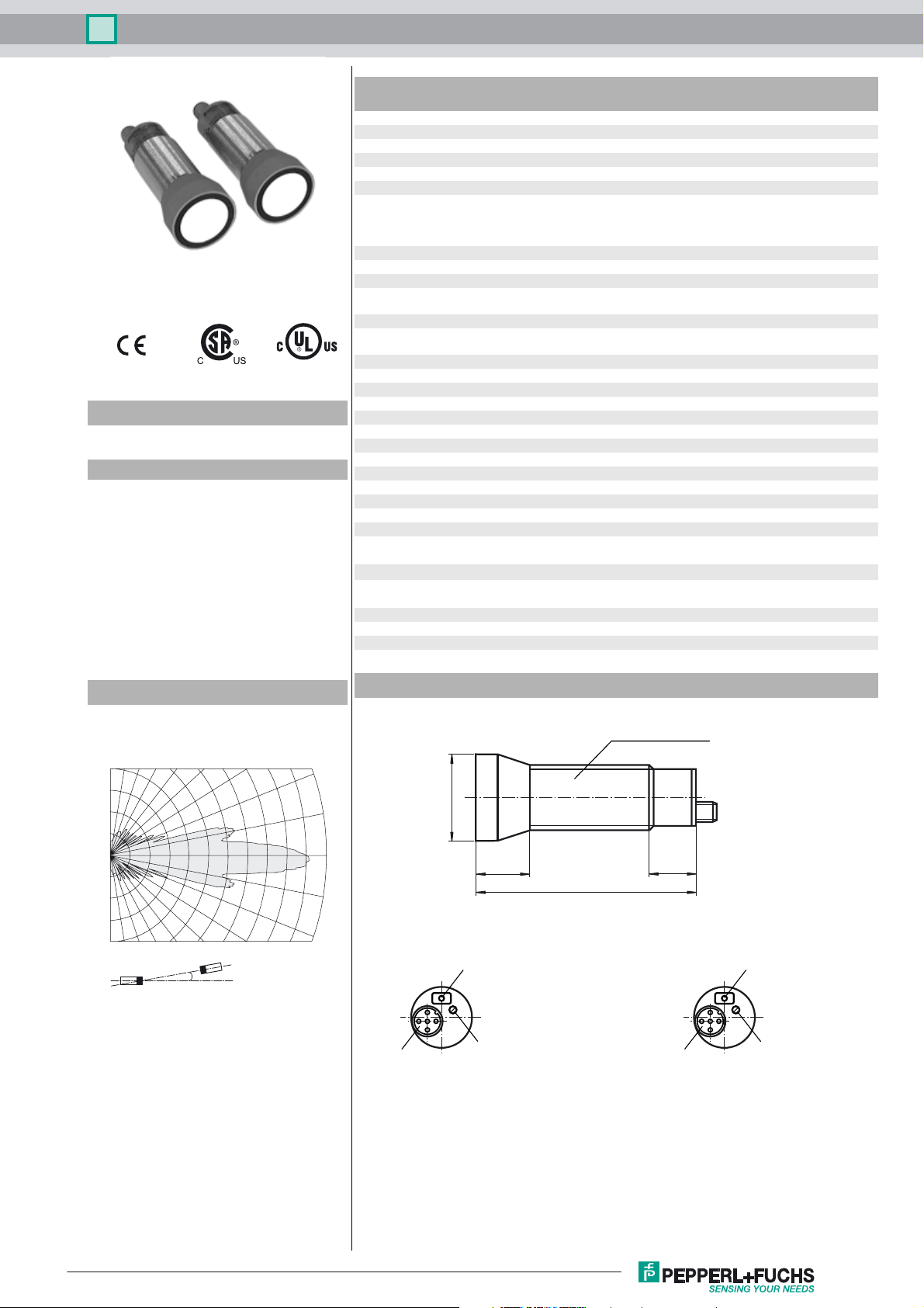
Diagrams
Characteristic response curves
90 80 70 60 50 40 30
0.0
0.5
1.0
1.5
2.0
Distance [m]
2.5 3.0 3.5 4.0 4.5 5.0 5.5
α
Angle [degrees]
Dimensions
Dimensions:
20
10
0
-10
-20
Emitter: Receiver:
ø40
25
LED green
internal distance regulator
Threaded pipe M30x1.5
90
22
Dual-LED
green/yellow
Plug connectorPlug connector
Potentiometer
ON delay
Release date: 2016-04-18 10:43 Date of issue: 2016-04-18 120344_eng.xml
Refer to “General Notes Relating to Pepperl+Fuchs Product Information”.
1
Through-beam ultrasonic barrier UBE4000-30GM-SA2-V15
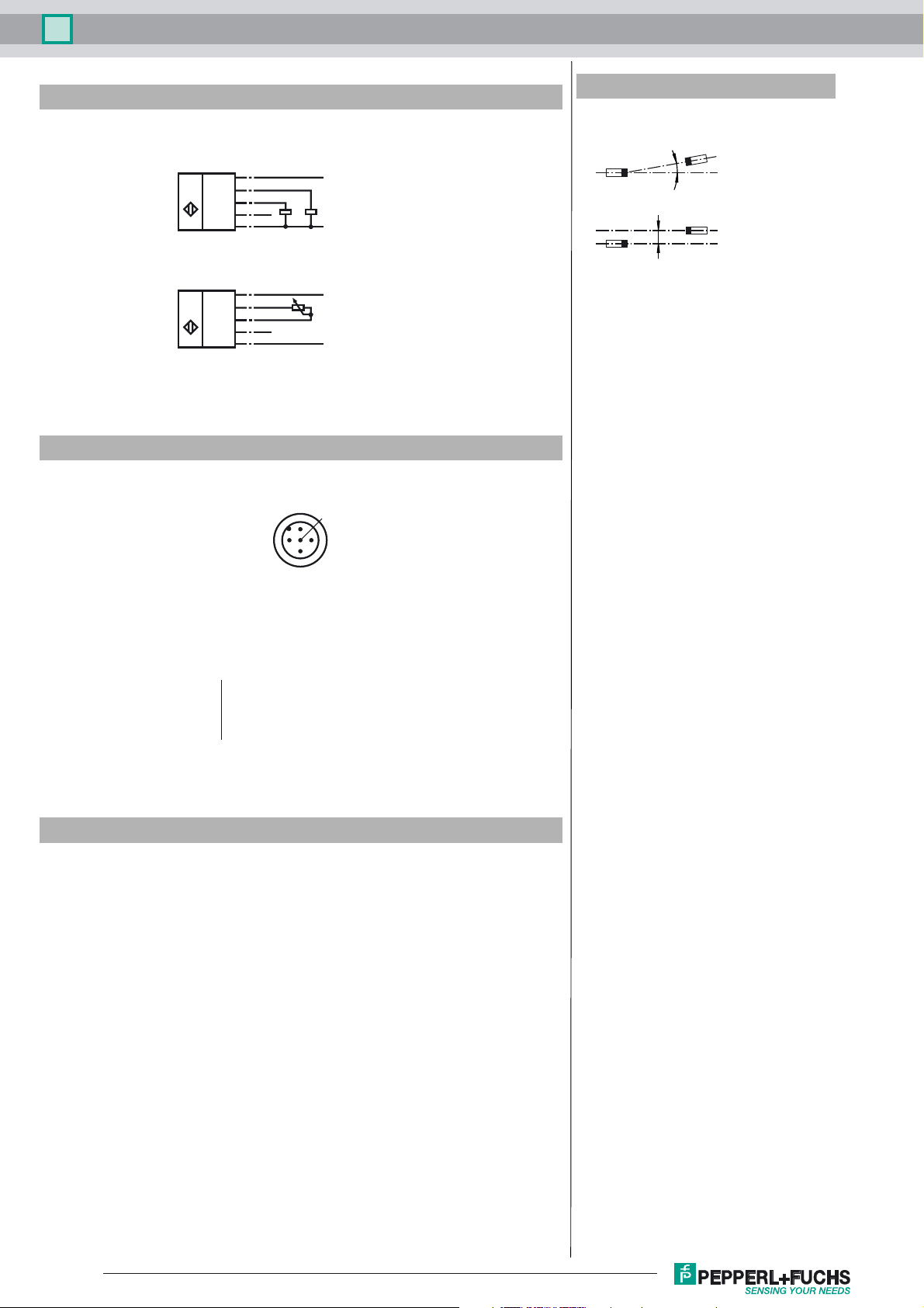
Electrical Connection
Standard symbol/Connection:
(version A2, pnp)
Receiver:
U
Emitter:
U
Core colours in accordance with EN 60947-5-2.
Pinout
Additional Information
Alignment
1
(BN)
(WH)
2
(BK)
4
5
n.c.
3
(BU)
1
(BN)
2
(WH)
4
(BK)
5
n.c.
3
(BU)
2
+U
B
N.C.N.O.
-U
B
+U
B
10k
-U
B
1
5
4
α
s
3
Wire colors in accordance with EN 60947-5-2
1 BN
2 WH
3 BU
4 BK
5 GY
(brown)
(white)
(blue)
(black)
(gray)
Accessories
FP100
Remote potentiometer
BF 30
Mounting flange, 30 mm
BF 5-30
Universal mounting bracket for cylindrical sensors with a diameter of 5 ... 30 mm
V1-G-2M-PVC
Female cordset, M12, 4-pin, PVC cable
Description of the sensor functions
Remote potentiometer
The distance range of the through-beam ultrasonic barrier can be adjusted with the
potentiometer integrated in the emitter, or via a remote potentiometer connected to
the emitter.
The remote potentiometer simplifies the adjustment of the distance range if the sensors are installed in an inaccessible location. A 10 kΩ/0.3 W potentiometer serves
as the remote potentiometer. The connection is realised using the plug connector
pins 2 and 4 of the emitter (see: Electrical Connection).
Release date: 2016-04-18 10:43 Date of issue: 2016-04-18 120344_eng.xml
Refer to “General Notes Relating to Pepperl+Fuchs Product Information”.
2
 Loading...