

Ultrasonic sensor, transmitter UBE15M-F54-H1-V1
Technical data
General specifications
Sensing range 0 ... 15000 mm , emitter - receiver synchronised
Transducer frequency approx. 40 kHz
Angle of divergence ± 45 ° at -6 dB
Model Number
UBE15M-F54-H1-V1
Multi-head system
Features
• Large sensing range
• Large possible lateral distance
between emitter and receiver
• Separate evaluation
Temperature drift of echo propagation
delay
Electrical specifications
Operating voltage U
No-load supply current I
Input
Input type 1 pulse input for transmitter pulse, activation through open
Pulse length 100 µs ... 10 ms
Pause length ≥ 50 x pulse length
Ambient conditions
Ambient temperature 0 ... 50 °C (32 ... 122 °F)
Storage temperature -40 ... 85 °C (-40 ... 185 °F)
Mechanical specifications
Connection type Connector M12 x 1 , 4-pin
Degree of protection IP30
Material
Housing PBT
Mass 110 g
Compliance with standards and
directives
Standard conformity
Standards EN 60947-5-2:2007 + A1:2012
Approvals and certificates
UL approval cULus Listed, General Purpose
CSA approval cCSAus Listed, General Purpose
CCC approval CCC approval / marking not required for products rated ≤36 V
B
0
0.2 %/K
16 ... 30 V DC , ripple 10 %SS
8 V DC with reduced transmitting power
≤ 10 mA (typ. 6 mA at UB = 24 V DC)
collector npn
< 1.5 V: emitter active, > 3.5 V: emitter inactive
IEC 60947-5-2:2007 + A1:2012
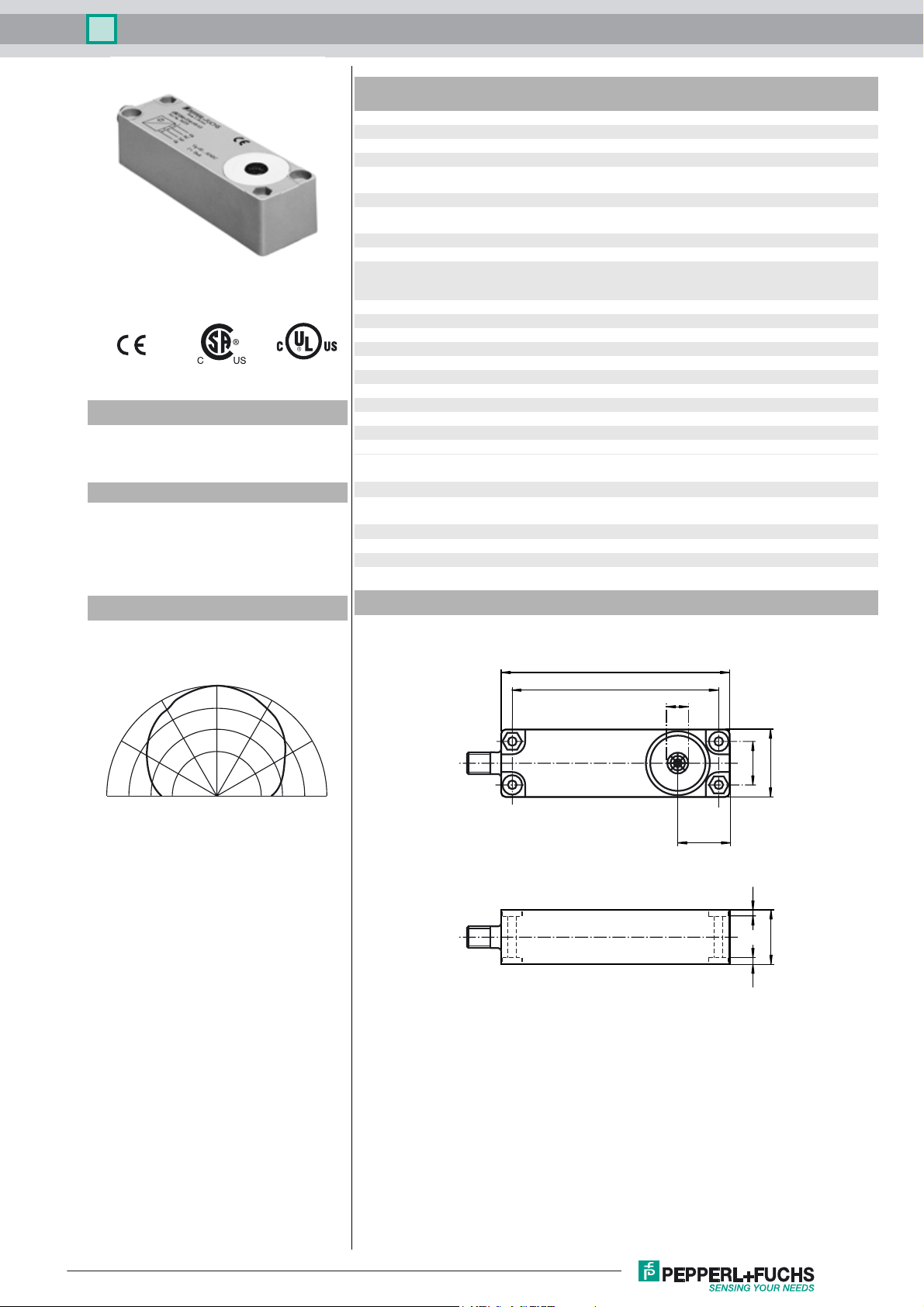
Diagrams
Direction characteristics
0°
30°
60°
90°
30°
60°
-10 0-20-30
Attenuation (dB)
Dimensions
90°
Bore hole and countersinking
for screws/hexagon M4
105
94
10
32
21
22
25
3.5 3.5
Release date: 2016-04-18 10:43 Date of issue: 2016-04-18 114519_eng.xml
Refer to “General Notes Relating to Pepperl+Fuchs Product Information”.
1
Ultrasonic sensor, transmitter UBE15M-F54-H1-V1
Electrical Connection
Standard symbol/Connection:
Emitter
Core colours in accordance with EN 60947-5-2.
(BN)
1
2
(WH)
3
(BU)
4
(BK)
+ U
nc
- U
Clock
B
B
Pinout
Connector V1
2
1
3
4
Function
The emitter is part of a complete system consisting of emitter, receiver and controller
Receiver: UBE15M-F54-H2-V1
Controller: UH3-16E4A-K15-R3
In real mode, the transmitter and receiver will not be not aligned to each other. This
reduces the detection range that can be achieved.
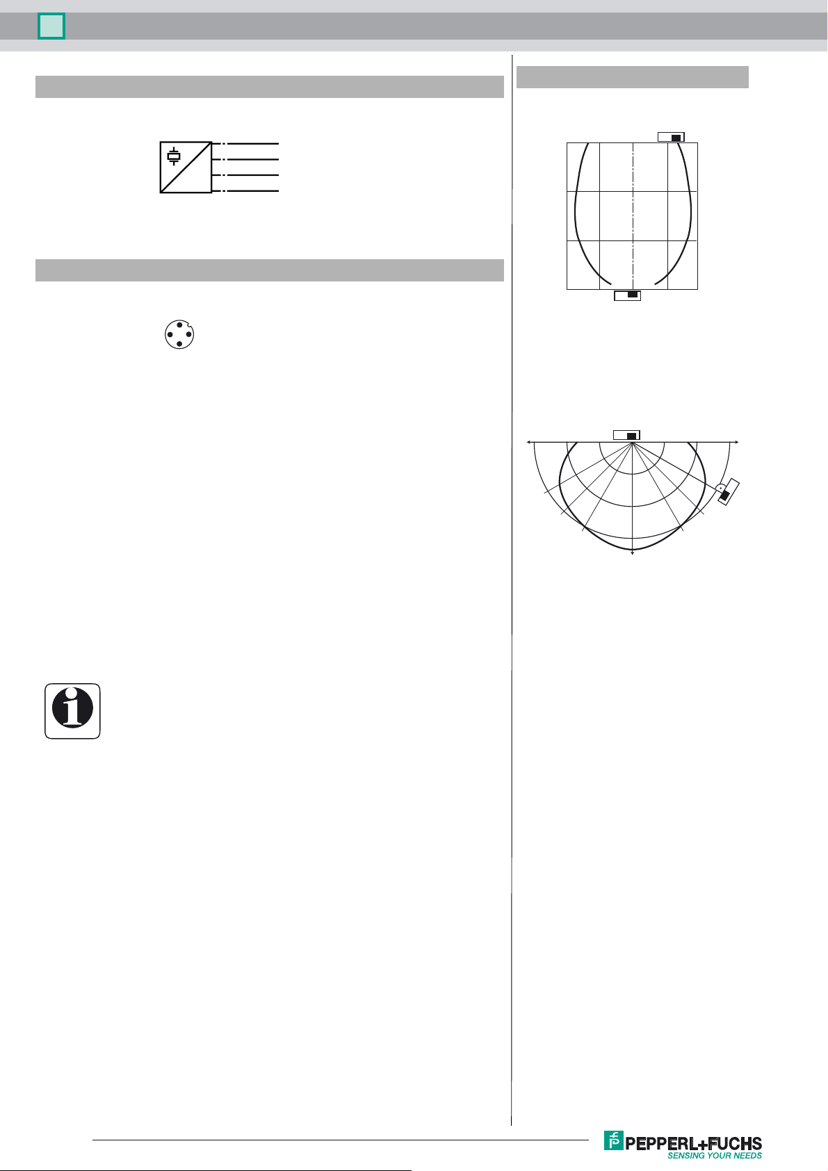
The characteristic response curve to the side illustrates examples of the detection
range of the system under the following operating conditions.
- The transmitter and receiver are arranged so they lie parallel opposite each other. The graph shows
the detection range as a function of lateral offset.
- The receiver is arranged vertically downward, while the emitter is arranged in the direction of the receiver. The graph shows the detection range as a function of the angle of incidence.
This makes it possible to evaluate the detection range of the system as a function of
the positioning of the transmitter and receiver for conditions that will occur in practical usage.
Additional Information
Characteristic response curve
Distance X [m]
15
10
5
0
10 5 -5 -10
Permissible distance (offset) between the optical axis of the
emitter and receiver.
Offset Y [m]
Characteristic response curve
15 m 10 m 5 m 5 m 10 m 15 m
30°
45°
60°
Information
Cable sockets with built-in indicator LEDs must not be used to
connect this device!
Release date: 2016-04-18 10:43 Date of issue: 2016-04-18 114519_eng.xml
Refer to “General Notes Relating to Pepperl+Fuchs Product Information”.
2
 Loading...