

Through-beam ultrasonic barrier UBE1000-18GM40A-SE2-V1
Technical data
General specifications
Sensing range 15 ... 1000 mm
Standard target plate 100 mm x 100 mm
Transducer frequency approx. 255 kHz
Indicators/operating means
LED green Power on
LED yellow switching state
LED red error, object uncertain
Electrical specifications
Model Number
UBE1000-18GM40A-SE2-V1
Single head system
Features
•Short design, 40mm
• Function indicators visible from all
directions
• Switch output
•Program input
• Integrated alignment aid
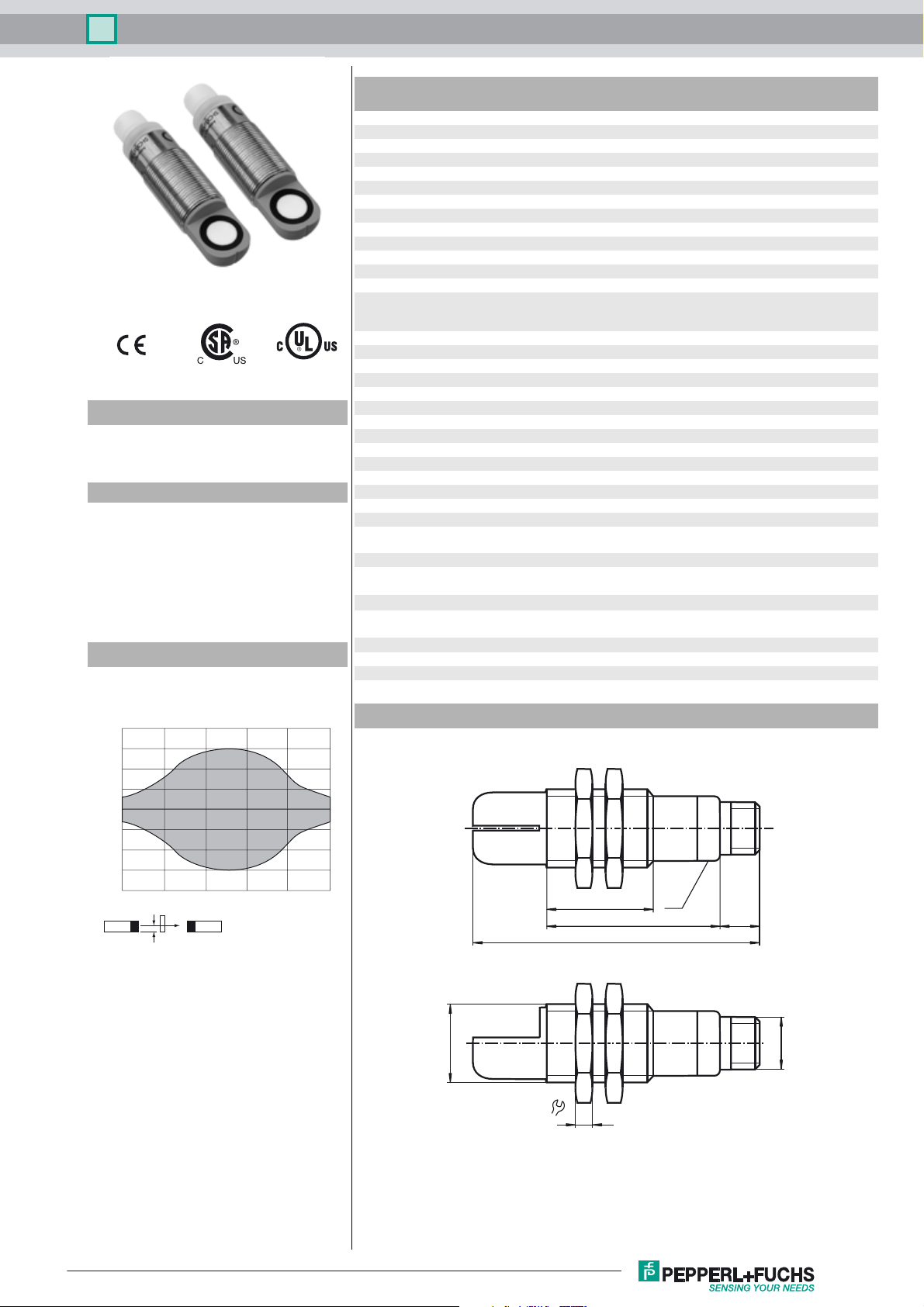
Diagrams
Characteristic response curve
Distance Y [mm]
20
15
10
5
0
-5
-10
-15
-20
0 200 400 600 800 1000
X
Y
Obstacle: flat plate 100 mm x 100 mm
Distance X [mm]
Operating voltage U
No-load supply current I
Time delay before availability t
Input
B
0
v
Input type 1 program input
Output
Output type PNP, NO
Rated operating current I
Voltage drop U
Switch-on delay t
d
Switching frequency f ≤ 100 Hz
e
on
Ambient conditions
Ambient temperature -25 ... 70 °C (-13 ... 158 °F)
Storage temperature -40 ... 85 °C (-40 ... 185 °F)
Mechanical specifications
Connection type Connector M12 x 1 , 4-pin
Degree of protection IP67
Material
Housing brass, nickel-plated
Transducer epoxy resin/hollow glass sphere mixture; foam polyurethane,
Mass 25 g
Compliance with standards and
directives
Standard conformity
Standards EN 60947-5-2:2007 + A1:2012
Approvals and certificates
UL approval cULus Listed, General Purpose
CSA approval cCSAus Listed, General Purpose
CCC approval CCC approval / marking not required for products rated ≤36 V
Dimensions
10 ... 30 V DC , ripple 10 %
≤ 20 mA
SS
≤ 200 ms
free air path: -U
input impedance: > 4,7 kΩ program pulse: ≥ 1 s
... +1 V, object: +6 V ... +UB
B
200 mA , short-circuit/overload protected
≤ 3 V
< 5 ms
cover PBT
IEC 60947-5-2:2007 + A1:2012
39.2
LED
10
24.5
67.7
Release date: 2016-04-18 10:43 Date of issue: 2016-04-18 205347_eng.xml
Refer to “General Notes Relating to Pepperl+Fuchs Product Information”.
Pepperl+Fuchs Group
M18 x 1
M12 x 1
24
4
1
Through-beam ultrasonic barrier UBE1000-18GM40A-SE2-V1
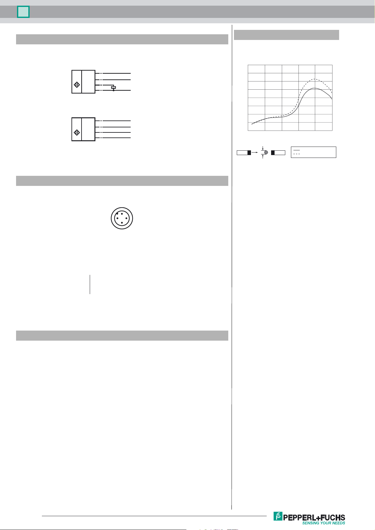
Electrical Connection
Standard symbol/Connection:
(version E2, pnp)
Receiver:
U
Emitter:
U
Core colours in accordance with EN 60947-5-2.
Pinout
Additional Information
Obstacle size
min. obstacle size d [mm]
80
(BN)
1
(WH)
2
4
(BK)
(BU)
3
(BN)
1
(WH)
2
(BK)
4
3
(BU)
+U
B
Teaching input
Switching output
-U
B
+U
B
Test input
n.c.
-U
B
1
70
60
50
40
30
20
10
0
0 200 400 600 800 1000
d
X
distance X [mm]
with Teach-In
without Teach-In
2
4
3
Wire colors in accordance with EN 60947-5-2
1 BN
2 WH
3 BU
4 BK
(brown)
(white)
(blue)
(black)
Accessories
UB-PROG2
Programming unit
OMH-04
Mounting aid for round steel ø 12 mm or sheet 1.5 mm ... 3 mm
BF 18
Mounting flange, 18 mm
BF 18-F
Mounting flange with dead stop, 18 mm
BF 5-30
Universal mounting bracket for cylindrical sensors with a diameter of 5 ... 30 mm
V1-G-2M-PVC
Female cordset, M12, 4-pin, PVC cable
V1-W-2M-PUR
Female cordset, M12, 4-pin, PUR cable
Function
A through-beam ultrasonic barrier always consists of a single emitter and a single
receiver. The function of a through-beam ultrasonic barrier is based in the interruption of the sound transmission to the receiver by the object to be detected.
The emitter sends an ultrasonic signal that is evaluated by the receiver. If the signal
is interrupted or muted by the object to be detected, the receiver switches.
No electrical connections are required between the emitter and receiver.
The function of through-beam ultrasonic barriers is not dependent on the position of
Refer to “General Notes Relating to Pepperl+Fuchs Product Information”.
2
Pepperl+Fuchs Group
Release date: 2016-04-18 10:43 Date of issue: 2016-04-18 205347_eng.xml
 Loading...