

Ultrasonic sensor UB500-30GM65-WS3-BHMS5
Technical data
General specifications
Sensing range 70 ... 500 mm
Unusable area 0 ... 70 mm
Standard target plate 100 mm x 100 mm
Transducer frequency 400 kHz
Response delay ≤ 45 ms
Indicators/operating means
LED green power
LED red output
Electrical specifications
Model Number
UB500-30GM65-WS3-BHMS5
Single head system
Features
• AC switchpoint output
• 330° high visibility LEDs
• Fingertip range adjustability
Diagrams
Operating voltage U
Power consumption P
Output
B
0
Output type Thyristor , 1 NO
Rated operating current I
Voltage drop U
Repeat accuracy ≤ 5 mm
d
e
Switching frequency f 15 Hz
Range hysteresis H approx. 15 mm
Temperature influence < 2 % of far switch point
Standard conformity
Standards EN 60947-5-2
Ambient conditions
Ambient temperature -25 ... 70 °C (-13 ... 158 °F)
Storage temperature -40 ... 85 °C (-40 ... 185 °F)
Mechanical specifications
Connection type 5-pin , V95 connector
Protection degree IP65
Material
Housing nickel plated brass; plastic components: PBT
Transducer epoxy resin/hollow glass sphere mixture; polyurethane foam
Approvals and certificates
UL approval cULus Listed, General Purpose
CSA approval cCSAus Listed, General Purpose
90 ... 140 V AC
≤ 75 mA
700 mA
≤ 1.5 V AC
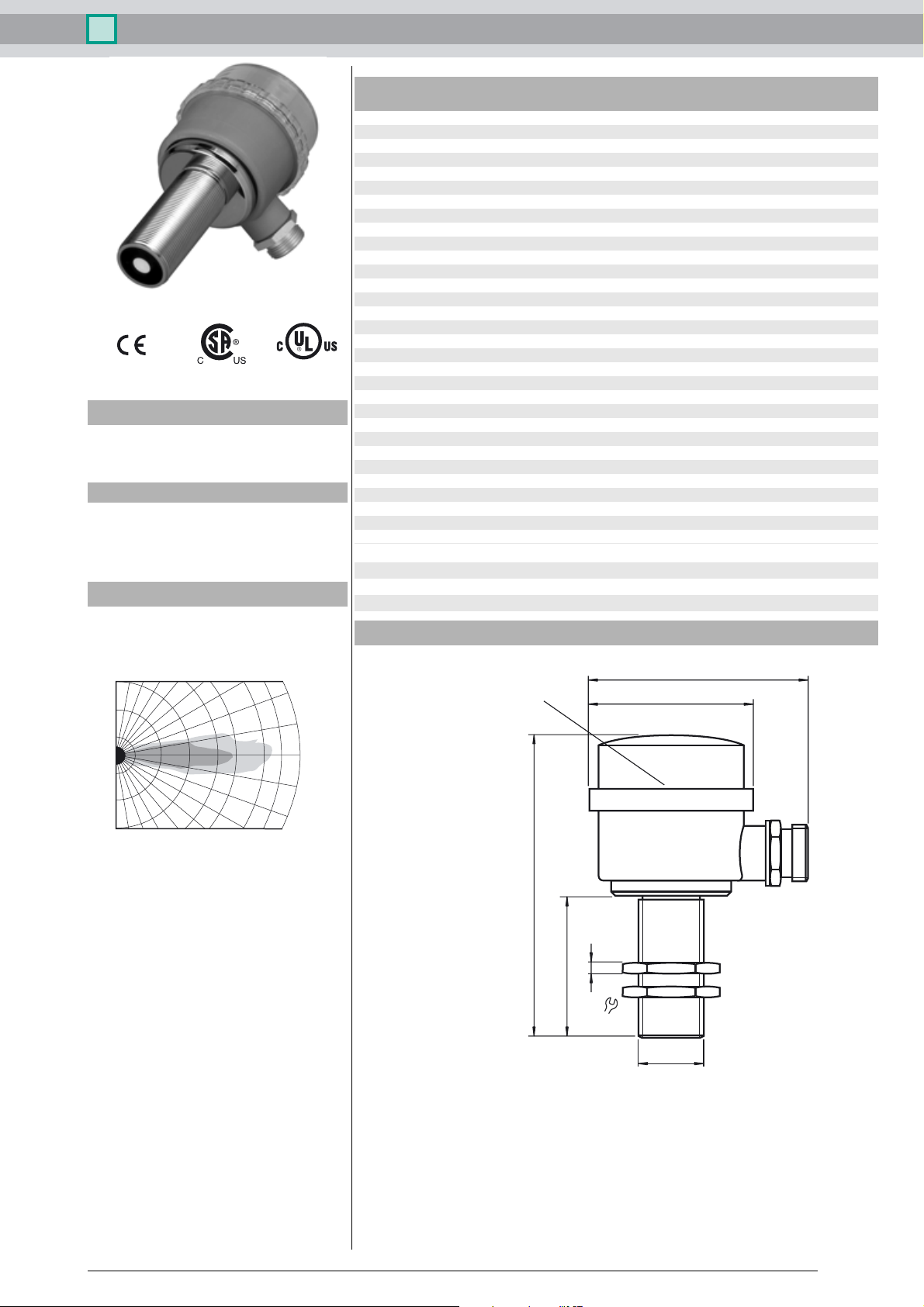
Characteristic response curve
1
0.70.60.50.4
Angle (degrees)
20
10
0
-10
-20
0.8
90 80 70 60 50 40 30
0.0
0.1
0.2
0.3
Distance (m)
Curve 1: Flat surface 100 mm x 100 mm
Curve 2: Round bar,
2
Ø 25 mm
Dimensions
LED indicators and set point
adjustment potentiometer
115
100
75
65
5
36
M30x1.5
Release date: 2013-02-14 15:00 Date of issue: 2013-02-14 093950_eng.xml
Subject to reasonable modifications due to technical advances. Copyright Pepperl+Fuchs, Printed in Germany
Pepperl+Fuchs Group • • • •
1
Ultrasonic sensor UB500-30GM65-WS3-BHMS5
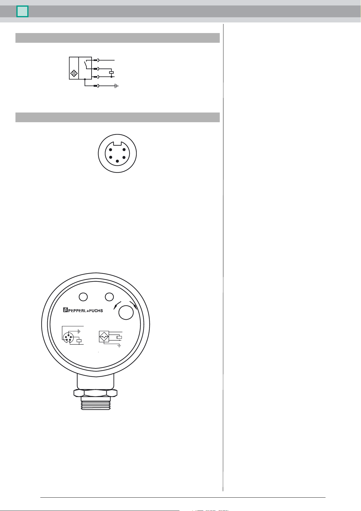
Electrical Connection
5
L1
2
1
N
3
Pinout
1
2
3
Adjustment procedure
The UB500 provides an N.O. switch point output between 70 mm (non-adjustable) and the potentiometer configured end point (70 - 500 mm). The sensing window end limit is adjusted as
follows:
1. Place the target at the desired distance
2. Turn the sensing potentiometer (on the back of the unit) counterclockwise until the red output LED turns off.
3. Slowly turn the potentiometer clockwise. The sensing range is set when the red output LED
turns on.
5
4
PowerOutput
Range
Twinsburg, Ohio 44087
Phone (330) 425-3555 MAX
Black
L1
Green
Red
LOAD
N.O.
L2
White
UB500-30GM65-WS3-BHMS5
P/N:
90-140 VAC, 800mA Max
MADE IN USA
Black
Red
White
Green
MIN
15 TURN
L1
LOAD
N.O.
L2
Installation conditions
If the sensor is installed in an environment where the temperature can fall below 0 °C, one of
these mounting flanges must be used for mounting: BF30, BF30-F, or BF 5-30.
If the sensor is mounted in a through hole using the included steel nuts, it must be mounted at
the middle of the threaded housing. If it must be mounted at the front end of the threaded housing, plastic nuts with centering ring (optional accessories) must be used.
Release date: 2013-02-14 15:00 Date of issue: 2013-02-14 093950_eng.xml
2
Subject to reasonable modifications due to technical advances. Copyright Pepperl+Fuchs, Printed in Germany
Pepperl+Fuchs Group • • • •
 Loading...