

Ultrasonic sensor UB400-F42S-UK-V95
Technical data
General specifications
Sensing range 40 ... 400 mm
Adjustment range 50 ... 400 mm
Dead band 0 ... 40 mm
Standard target plate 100 mm x 100 mm
Transducer frequency approx. 390 kHz
Response delay approx. 50 ms
Indicators/operating means
LED green solid green: Power on
Model Number
UB400-F42S-UK-V95
Single head system
Features
• Relay output for high power
• Extremely small unusable area
•TEACH-IN
• Interference suppression
(adjustable divergence of sound
cone in close range)
• Temperature compensation
• NO/NC selectable
Diagrams
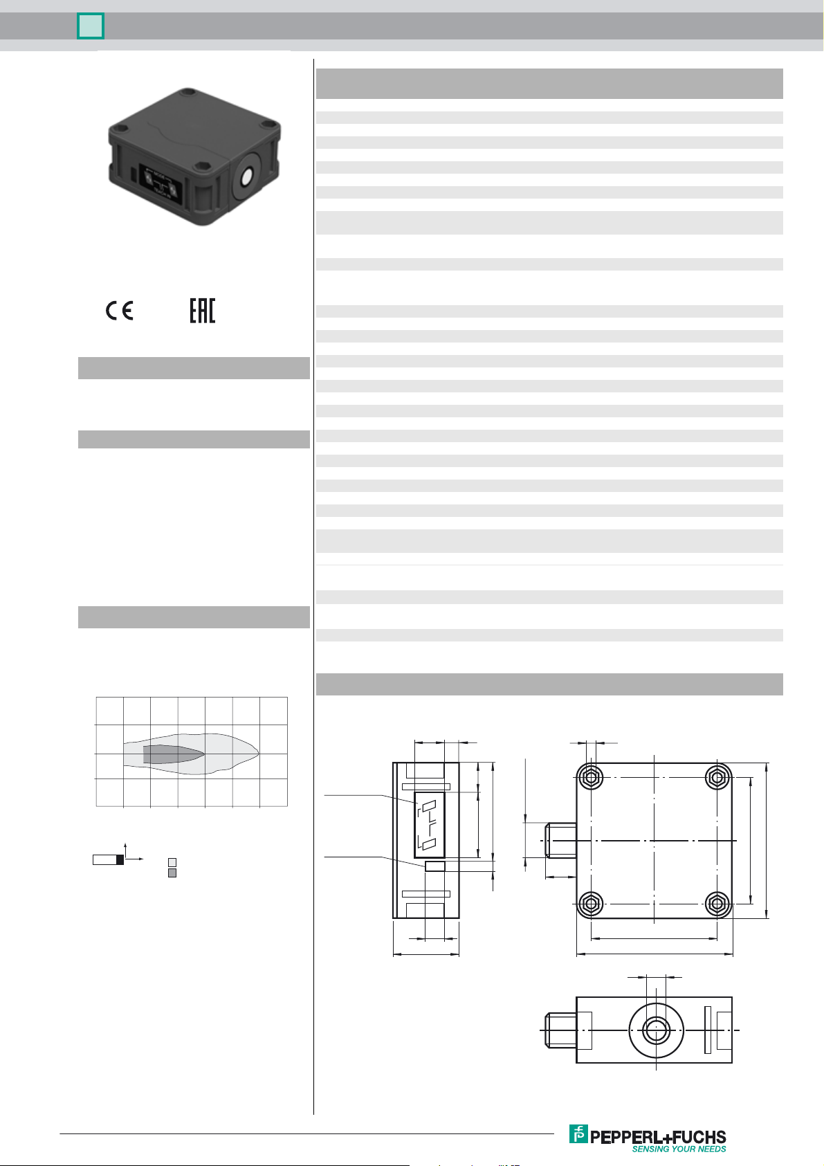
Characteristic response curve
LED yellow solid: switching state switch output
LED red normal operation: "fault"
Electrical specifications
Fusing ≤ 3 A Slow-blow fuse in accordance with IEC 60127-2
Operating voltage U
No-load supply current I
Time delay before availability t
Output
B
0
v
Output type 1 relay output
Rated operating current I
Repeat accuracy ≤ 0.5 % of switching point
e
Switching frequency f ≤ 8 Hz
Range hysteresis H 1 % of the set operating distance
Temperature influence ± 1 % of full-scale value
Ambient conditions
Ambient temperature -25 ... 70 °C (-13 ... 158 °F)
Storage temperature -40 ... 85 °C (-40 ... 185 °F)
Mechanical specifications
Degree of protection IP65
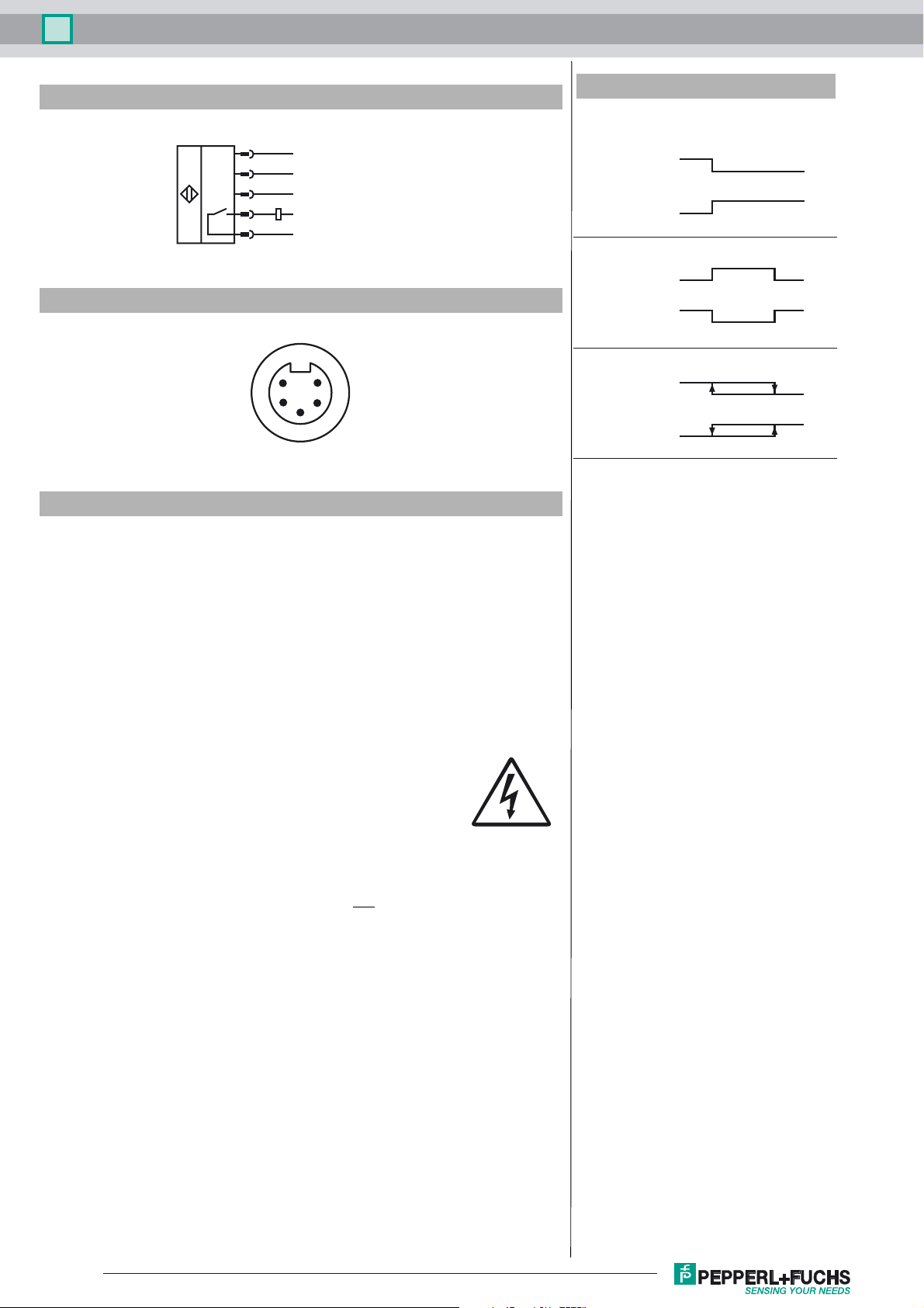
Connection 5-pin V95 connector (7/8"-16 UN 2A)
Material
Housing PBT
Transducer epoxy resin/hollow glass sphere mixture; foam polyurethane,
Mass 260 g
Compliance with standards and
directives
Standard conformity
Standards EN 60947-5-2:2007+A1:2012
Approvals and certificates
EAC conformity TR CU 004/2011
flashing: program function
program function: no object detected
Sheet 5 required. Recommendation: after a short circuit,
check that the device is functioning correctly.
22 ... 253 V AC/DC
≤ 60 mA
≤ 800 ms
3 A
cover PBT
IEC 60947-5-2:2007 + A1:2012
TR CU 020/2011
Distance Y [m]
0.2
0.1
0
-0.1
-0.2
0.0 0.1 0.2 0.3 0.4 0.5 0.6 0.7
Y
X
Flat surface 100 mm x 100 mm
Round bar, Ø 25 mm
Distance X [m]
Dimensions
Membrane keys
LED window
15
MODE
34
7.5
15.5
2
A
34
TEACH IN
1
A
10
52.5
5
7/8"-16 UN 2A
16
5.2
80
65
65
80
10
Release date: 2017-08-24 08:53 Date of issue: 2017-08-24 111682_eng.xml
Refer to “General Notes Relating to Pepperl+Fuchs Product Information”.
1
Ultrasonic sensor UB400-F42S-UK-V95
Electrical Connection
1
5
3
4
2
22 V ... 253 V ~/=
22 V ... 253 V ~/=
n.c.
≤
250 V ~/120 V =
≤
3 A
I
Pinout
1
2
3
5
4
Accessories
V95-G-Y
Female connector, 7/8" - 16 UN, 5-pin, field attachable
V95-W-5M-PVC
Female cordset, 7/8", 5-pin, PVC cable
V95-W
Female cordset, field attachable
V95-W-2M-PVC
Female cordset, 7/8", 5-pin, PVC cable
MH 04-3505
Mounting aid for FP and F42 sensors
MHW 11
Mounting brackets for sensors
Additional Information
Possible operating modes
1. Switch point operation
normally open
A1 -> ∞
normally closed
A2 -> ∞
2. Window operation
normally open
A1 < A2
normally closed
A2 < A1
3. Hysteresis operation
normally open
A1 < A2
normally closed
A2 < A1
4. Object presence detection mode
A1 -> ∞, A2 -> ∞: Sensor detects object presence within
sensing range
Note A1 -> ∞, A2 -> ∞ means: cover sensor with hand
or remove all objects from sensing range
A2
A1
A1 A2
A2 A1
A1 A2
A2 A1
Safety notes:
The supply circuit is separated from the relay circuit by basic insulation.
Safety class II is only guaranteed when using cable connectors listed in the accessories. The connector cable may only be separated
from the unit when the power is off.
CAUTION:
The UB...-F42(S)-UK-V95 ultrasonic sensor is not
suitable for use in environ-
ments subject to explosion hazards.
Conformity: EN 60947-5-2
Housing insulation: Safety class II
Degree of contamination: 3
Overvoltage category: III
Parameterisation:
You can use 2 keys to parameterise the sensor. In order to start the switch point 1
learning mode, press the A1 key; in order to start the switch point 2 learning mode,
press the A1 key.
If you keep both keys pressed as you switch on the power supply, the sensor will
switch over to the sensitivity adjustment mode of operation.
In case the parameterisation procedure is not completed within 5 minutes, the sensor
will discontinue the process and retain all previous settings.
Release date: 2017-08-24 08:53 Date of issue: 2017-08-24 111682_eng.xml
Refer to “General Notes Relating to Pepperl+Fuchs Product Information”.
2
 Loading...