

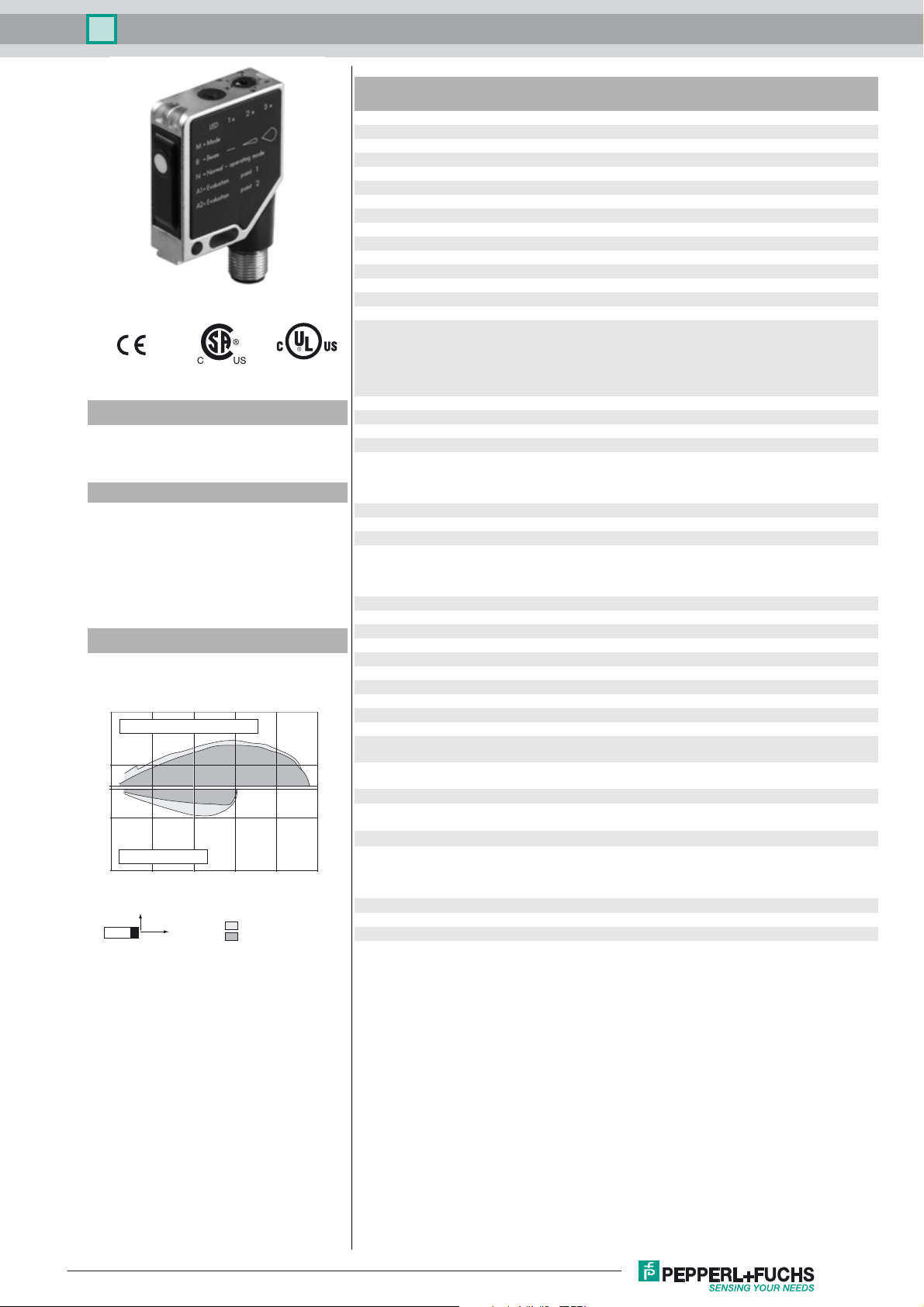
Ultrasonic sensor UB250-F12-I-V15
Technical data
General specifications
Sensing range 20 ... 250 mm
Adjustment range 25 ... 250 mm
Dead band 0 ... 20 mm
Standard target plate 100 mm x 100 mm
Transducer frequency approx. 400 kHz
Response delay approx. 20 ms
Indicators/operating means
LED green Operating display
LED yellow Evaluation range indicator, Ready for programming
LED red Ready for programming, Fault
Electrical specifications
Model Number
UB250-F12-I-V15
Single head system
Features
• Evaluation limits can be taught-in
• Selectable sound lobe width
• Synchronization options
• Very small unusable area
• Temperature compensation
Diagrams
Characteristic response curve
Distance Y [mm]
70
flat surface 100 mm x 100 mm
20
0
-30
round bar, Ø 25 mm
-80
0 100 200 300 400 500
Y
X
wide sound lobe
narrow sound lobe
Distance X [mm]
Operating voltage U
No-load supply current I
Input/Output
Synchronization 1 synchronous connection, bi-directional
Synchronization frequency
Common mode operation ≤ 200 Hz
Multiplex operation ≤ 200/n Hz, n = number of sensors
Input
Input type 1 program input
Pulse length ≥ 1 s
Output
Output type 1 analog output 4 ... 20 mA
Default setting evaluation limit A1: 25 mm
Repeat accuracy ≤ 1 %
Load impedance ≤ 1000 Ohm
Temperature influence ± 1.5 % of full-scale value
Ambient conditions
Ambient temperature -15 ... 70 °C (5 ... 158 °F)
Storage temperature -40 ... 85 °C (-40 ... 185 °F)
Mechanical specifications
Connection type Connector M12 x 1 , 5-pin
Degree of protection IP54
Material
Housing Frame: nickel plated, die cast zinc,
Transducer epoxy resin/hollow glass sphere mixture; foam polyurethane,
Mass 60 g
Compliance with standards and
directives
Standard conformity
Standards EN 60947-5-2:2007 + A1:2012
Approvals and certificates
UL approval cULus Listed, General Purpose
CSA approval cCSAus Listed, General Purpose
B
0
10 ... 30 V DC
≤ 30 mA
0-level: -U
1-level: +4 V...+U
input impedance: > 12 kΩ
synchronization pulse: ≥ 100 µs, synchronization interpulse
period: ≥ 2 ms
Switching distance 1: -U
... +U
Input impedance: > 10 kΩ
evaluation limit A2: 250 mm
wide sound lobe
rising ramp
Laterals: glass-fiber reinforced plastic PC
cover PBT
IEC 60947-5-2:2007 + A1:2012
EN 60947-5-7:2003
IEC 60947-5-7:2003
...+1 V
B
B
... +1 V, Sw itch ing d ista nce 2 : +3 V
B
B
Release date: 2016-04-25 09:27 Date of issue: 2016-04-25 202071_eng.xml
Refer to “General Notes Relating to Pepperl+Fuchs Product Information”.
1
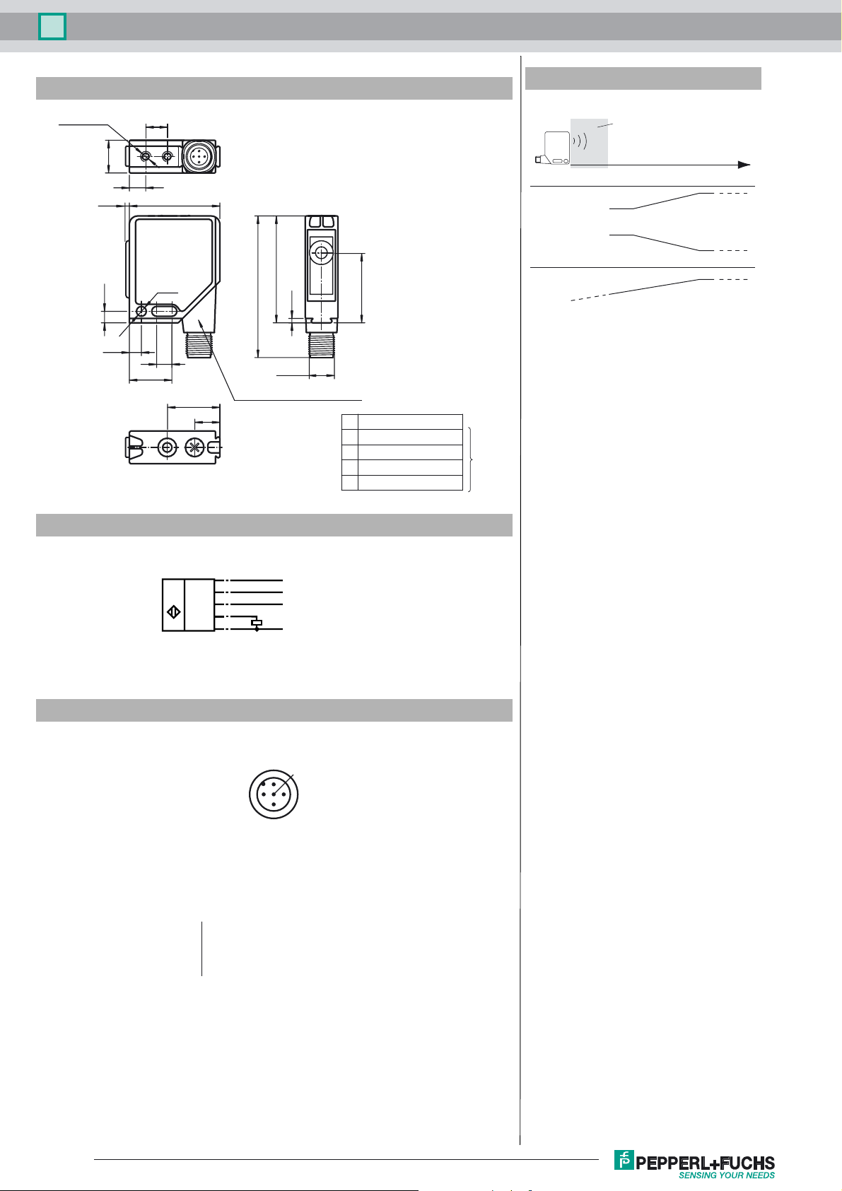
Ultrasonic sensor UB250-F12-I-V15
Dimensions
M4 / 4 deep
15
1.5
5.3
5.5
7.5
19.5
Additional Information
Analogue output programmation
10
41.5
ø4.5
7
49
65
2
M12 x 1
24
A1
N
M
Connector 90° adjustable position
11.5
A2
B
32.5
N normal operation
A1 evaluation limit 1
A2 evaluation limit 2
B light beam characteristics
M operating mode
Teach-IN
Rising ramp
Falling ramp
Zero line
A1 = 0
Unusable area
A1A1
A1 A2
Object distance
A2
A2
Electrical Connection
Standard symbol/Connections:
(version I)
U
Core colours in accordance with EN 60947-5-2.
Pinout
Wire colors in accordance with EN 60947-5-2
1 BN
2 WH
3 BU
4 BK
5 GY
(BN)
1
(WH)
2
(GY)
5
(BK)
4
(BU)
3
2
+ U
B
Teaching input
Sync.
Analog output
- U
B
1
5
4
3
(brown)
(white)
(blue)
(black)
(gray)
Release date: 2016-04-25 09:27 Date of issue: 2016-04-25 202071_eng.xml
Refer to “General Notes Relating to Pepperl+Fuchs Product Information”.
2
 Loading...