

Ultrasonic sensor UB250-F12-EP-V15
Technical data
General specifications
Sensing range 20 ... 250 mm
Adjustment range 25 ... 250 mm
Dead band 0 ... 20 mm
Standard target plate 100 mm x 100 mm
Transducer frequency approx. 400 kHz
Response delay approx. 20 ms
Indicators/operating means
LED green Operating display
LED yellow Evaluation range indicator, Ready for programming
LED red Ready for programming, Fault
Electrical specifications
Model Number
UB250-F12-EP-V15
Single head system
Features
• Evaluation limits can be taught-in
• Selectable sound lobe width
• Synchronization options
• Very small unusable area
• Temperature compensation
Diagrams
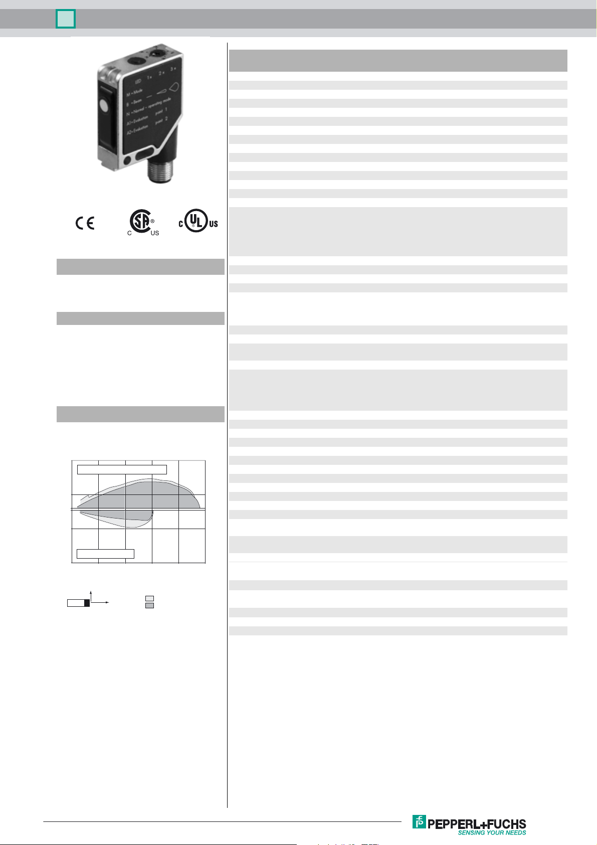
Characteristic response curve
Distance Y [mm]
70
flat surface 100 mm x 100 mm
20
0
-30
round bar, Ø 25 mm
-80
0 100 200 300 400 500
Y
X
wide sound lobe
narrow sound lobe
Distance X [mm]
Operating voltage U
No-load supply current I
Input/Output
Synchronization 1 synchronous connection, bi-directional
Synchronization frequency
Common mode operation ≤ 200 Hz
Multiplex operation ≤ 200/n Hz, n = number of sensors
Input
Input type 1 program input
Pulse length ≥ 1 s
Output
Output type Push-pull output, short-circuit protected, reverse polarity
Rated operating current I
Default setting near switch point: 25 mm
Voltage drop U
Repeat accuracy ≤ 1 %
Switching frequency f 20 Hz
Range hysteresis H 1 % of the set operating distance
Temperature influence ± 1.5 % of full-scale value
Ambient conditions
Ambient temperature -15 ... 70 °C (5 ... 158 °F)
Storage temperature -40 ... 85 °C (-40 ... 185 °F)
Mechanical specifications
Connection type Connector M12 x 1 , 5-pin
Degree of protection IP54
Material
Housing Frame: nickel plated, die cast zinc,
Transducer epoxy resin/hollow glass sphere mixture; foam polyurethane,
Mass 60 g
Compliance with standards and
directives
Standard conformity
Standards EN 60947-5-2:2007 + A1:2012
Approvals and certificates
UL approval cULus Listed, General Purpose
CSA approval cCSAus Listed, General Purpose
B
0
e
d
10 ... 30 V DC
≤ 30 mA
0-level: -U
1-level: +4 V...+U
input impedance: > 12 kΩ
synchronization pulse: ≥ 100 µs, synchronization interpulse
period: ≥ 2 ms
Switching distance 1: -U
... +U
Input impedance: > 10 kΩ
protected
200 mA , short-circuit/overload protected
far switch point: 250 mm
wide sound lobe
output function: Window mode
output behavior: NO contact
≤ 3 V
Laterals: glass-fiber reinforced plastic PC
cover PBT
IEC 60947-5-2:2007 + A1:2012
...+1 V
B
B
... +1 V, Sw itch ing d ista nce 2 : +3 V
B
B
Release date: 2016-04-25 09:32 Date of issue: 2016-04-25 202070_eng.xml
Refer to “General Notes Relating to Pepperl+Fuchs Product Information”.
1
Ultrasonic sensor UB250-F12-EP-V15
Dimensions
M4 / 4 deep
15
1.5
5.3
5.5
10
7.5
41.5
ø4.5
7
19.5
Electrical Connection
Standard symbol/Connections:
(version EP, pnp/npn)
U
Core colours in accordance with EN 60947-5-2.
Additional Information
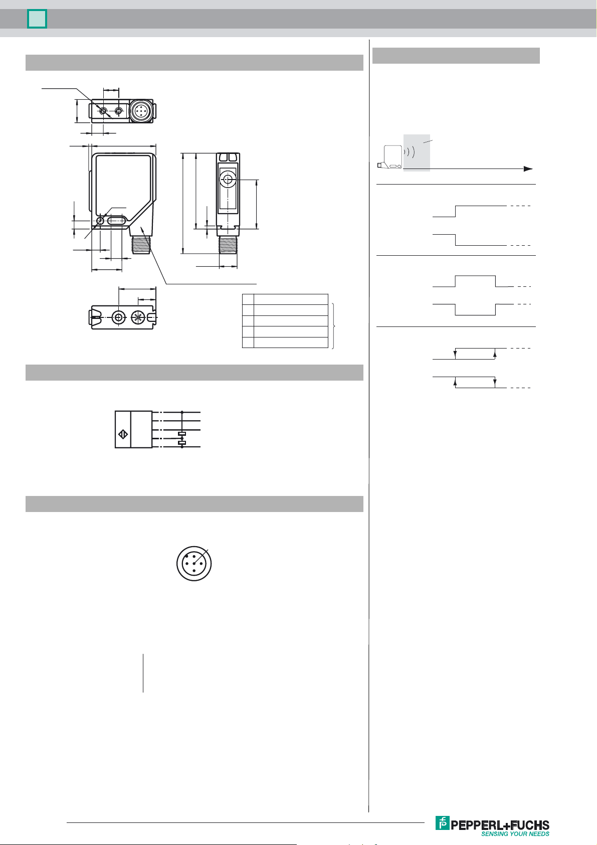
Programmable operation modes
Unusable area
Object distance
49
65
2
M12 x 1
24
A1
N
M
Connector 90° adjustable position
11.5
A2
B
(BN)
1
(WH)
2
(GY)
5
(BK)
4
(BU)
3
+ U
B
TEACH
Synchronous
Switch output
- U
B
32.5
N normal operation
A1 evaluation limit 1
A2 evaluation limit 2
B light beam characteristics
M operating mode
Teach-IN
1. Switching point mode
N. C.
A1
N. O.
A2
2. Window mode
N. O.
A2 > A1
N. C.
A1> A2
A1
A2 A1
3. Hysteresis mode
N. C.
A2 > A1
N. O.
A1 > A2
A1
A2
A2
A2
A1
Pinout
1
5
2
4
3
Wire colors in accordance with EN 60947-5-2
1 BN
2 WH
3 BU
4 BK
5 GY
(brown)
(white)
(blue)
(black)
(gray)
Release date: 2016-04-25 09:32 Date of issue: 2016-04-25 202070_eng.xml
Refer to “General Notes Relating to Pepperl+Fuchs Product Information”.
2

Ultrasonic sensor UB250-F12-EP-V15
Accessories
OMH-K01
dove tail mounting clamp
OMH-K02
dove tail mounting clamp
OMH-K03
dove tail mounting clamp
OMH-01
Mounting aid for round steel ø 12 mm or sheet 1.5 mm ... 3 mm
OMH-06
Mounting aid for round steel ø 12 mm or sheet 1.5 mm ... 3 mm
OMH-MLV12-HWG
Mounting bracket for series MLV12 sensors
OMH-MLV12-HWK
Mounting bracket for series MLV12 sensors
V15-G-2M-PVC
Female cordset, M12, 5-pin, PVC cable
Function description
The sensor can be fully programmed by means of a push button and a selector switch on the top of the housing. A special feature of this sensor is the option
of adapting the breadth of the ultrasonic beam to suit the ambient conditions at the point of use.
Normal operation
During normal operation the output stage of the sensor operates in accordance with the taught-in evaluation limits, the programmed mode of operation and
characteristic of the sonic beam. In this made the selector switch must remain at the N position.
LED Condition
Green LED Continuous: Ready for operation
Yellow LED Object detected within the evaluation limits
If the selector switch is not in the N position when the power supply is switched on, then this is indicated by simultaneous flashing of the green and yellow
LEDs. However, the function of the output stage is as for the switch position N.
Teaching in of the switching points:
Within a time window of 5 minutes after switch-on of the power supply the sensor is ready for adaptation of the switching points to the requirements of the
respective application.
Note: For switching point mode, depending on the desired output behaviour (N. O. or N. C.), it is necessary to teach only one switching point, either A1 or
A2. For the operating modes window mode and hysteresis mode, both A1 and A2 are reqiured to be taught to the sensor.
- Place the object that is to be detected at the desired position.
- Set the selector switch to position A1 or A2.
- Now actuate the TEACH-IN button.
LED before pressing button on pressing button after pressing button
Green Off Off On
Yellow Flashes: Positive detection
On switching output state
of object
Red Flashes: No object detected
Off Off
On: Object not positively
detected
- The teach-in procedure for the evaluation range limit can be repeated by repeatedly actuating the TEACH-IN button.
- Return the selector switch to position N.
Note: Acceptance of the switching point into the permanent memory of the sensor does not take place until the selector switch is reset to N. If this acceptance does not take place within a time window of 5 minutes, the sensor continues to operate with unchanged values and the red and yellow LEDs
flash.
With the Output functions window mode and hysteresis mode, the teach in sequence of the switching points is arbitrary. With the output function switching
point mode, the last taught point (A1 or A2) determins the output behaviour (N. O. or N. C.).
Alternatively, the switching points can be set electrically, via the teach-in input. In this case the selector switch is left in the N position. The two switching
points are taught in by applying the potentials -U
(A1) and +UB (A2), respectively, for at least 500 ms to the teach-in input.
B
Parameter assignment of the operating mode
Within a time window of 5 minutes from switching on the power supply the sensor is ready for adaptation of the output function.
- Set the selector switch to position M (Mode). The current set operating mode is indicated by the flashing sequence of the green LED.
- The optional operating modes are selected by briefly actuating the TEACH-IN button (See flashing sequence of the green LED).
Release date: 2016-04-25 09:32 Date of issue: 2016-04-25 202070_eng.xml
Refer to “General Notes Relating to Pepperl+Fuchs Product Information”.
3

Ultrasonic sensor UB250-F12-EP-V15
Operating mode Flashing sequence of the green LED T button
Switching point mode
Window mode
Hysteresis mode
pause
Pause
Pause
Pause
- Return the selector switch to position N when the desired operating mode is displayed.
Note: Acceptance of the operating mode into the permanent memory of the sensor does not take place until the selector switch is set to N. If this acceptance does not take place within a time window of 5 minutes, the sensor continues to operate with unchanged operating mode and the red and yellow
LEDs flash.
Parameter assignment of the ultrasonic beam breadth
Within a time window of 5 minutes from switching on the power supply the sensor is ready for adaptation of the ultrasonic beam breadth.
- Set the selector switch to position B (Beam). The flashing sequence of the green LED indicates the currently set ultrasonic beam breadth.
- The optional beam breadths are selected by brief actuation of the TEACH-IN button (See flashing sequence of the green LED).
Characteristic Flashing sequence of the green LED T-Button
Narrow beam
Medium beam
Broad beam
Pause
Pause
Pause
- Return the selector switch to position N when the desired beam breadth is indicated.
Note: Acceptance of the ultrasonic beam breadth into the permanent memory of the sensor does not take place until the selector switch is set to N. If this
acceptance does not take place within the 5 minute time window, the sensor continues its operation with an unchanged ultrasonic beam breadth and the
red and yellow LEDs flash.
Synchronisation
A synchronisation connection is provided for the suppression of mutual interference. If this is unused, or connected to 0V, then the sensor operates with an
internally generated clock-pulse rate. The synchronisation of a number of sensors can be achieved by the following means.
External synchronisation:
The sensor can be synchronised by the external application of a square-wave voltage. A synchronisation pulse at the synchronisation input leads to the
execution of a measuring cycle. The pulse width must be greater than 1.2 ms. The measuring cycle starts with the falling ramp. A low level > 1 s or an open
synchronisation input leads to the normal operation of the sensor. A high level at the synchronisation input deactivates the sensor.
Two operating modes are possible.
- A number of sensors are triggered by the same synchronisation signal. The sensors operate in common mode.
- The synchronisation pulses are fed cyclically to one sensor at a time. The sensors operate in multiplex mode.
Self-synchronisation:
The synchronisation connections of up to 5 sensors are connected together to provide the option of self-synchronisation. When the operating voltage is
switched on these sensors operate in multiplex mode. The switch-in delay increases depending on the number of sensors to be synchronised. Synchronisation cannot take place during teach-in and vice-versa. The sensors must be operated unsynchronised for the teaching-in of the switch points.
Note:
If the synchronisation option is not used, then the synchronisation input is connected to earth (0V) or the sensor is operated with a V1 connection cable (4pole).
Release date: 2016-04-25 09:32 Date of issue: 2016-04-25 202070_eng.xml
Refer to “General Notes Relating to Pepperl+Fuchs Product Information”.
4
 Loading...