

Pepperl Fuchs UB200-12GM-I-V1 Data Sheet
Ultrasonic sensor UB200-12GM-I-V1
Technical data
General specifications
Sensing range 15 ... 200 mm
Adjustment range 20 ... 200 mm
Dead band 0 ... 15 mm
Standard target plate 100 mm x 100 mm
Transducer frequency approx. 400 kHz
Response delay approx. 30 ms
Indicators/operating means
Model Number
UB200-12GM-I-V1
Single head system
Features
•Analog output 4mA...20mA
• Very small unusable area
• Measuring window adjustable
•Program input
• Temperature compensation
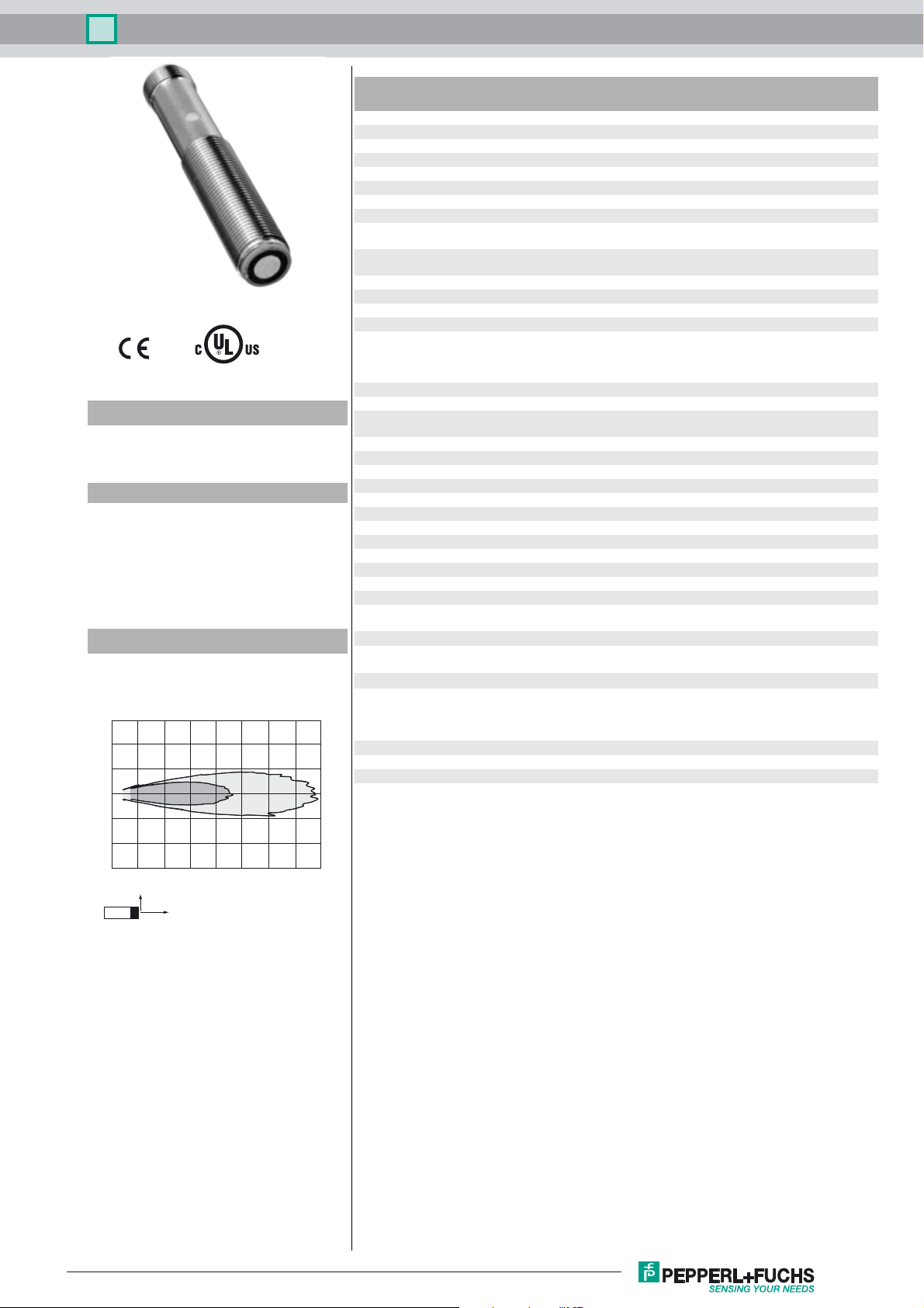
Diagrams
Characteristic response curve
Distance Y [mm]
150
100
50
0
-50
-100
-150
0 50 100 150 200 250 300 350 400
Y
Curve 1: flat surface 100 mm x 100 mm
Curve 2: round bar, Ø 25 mm
2
X
1
Distance X [mm]
LED yellow solid yellow: object in the evaluation range
LED red solid red: Error
Electrical specifications
Operating voltage U
No-load supply current I
Input
Input type 1 program input
Output
Output type 1 analog output 4 ... 20 mA
Resolution 0.17 mm
Deviation of the characteristic curve ± 1 % of full-scale value
Repeat accuracy ± 0.5 % of full-scale value
Load impedance 0 ... 200 Ω
Temperature influence ± 1.5 % of full-scale value
Ambient conditions
Ambient temperature -25 ... 70 °C (-13 ... 158 °F)
Storage temperature -40 ... 85 °C (-40 ... 185 °F)
Mechanical specifications
Connection type Connector M12 x 1 , 4-pin
Degree of protection IP67
Material
Housing brass, nickel-plated
Transducer epoxy resin/hollow glass sphere mixture; foam polyurethane,
Mass 25 g
Compliance with standards and
directives
Standard conformity
Standards EN 60947-5-2:2007+A1:2012
Approvals and certificates
UL approval cULus Listed, Class 2 Power Source
CCC approval CCC approval / marking not required for products rated ≤36 V
B
0
yellow, flashing: program function, object detected
red, flashing: program function, object not detected
10 ... 30 V DC , ripple 10 %
≤ 30 mA
lower evaluation limit A1: -U
A2: +4 V ... +U
input impedance: > 4.7 kΩ, pulse duration: ≥ 1 s
cover PBT
IEC 60947-5-2:2007 + A1:2012
EN 60947-5-7:2003
IEC 60947-5-7:2003
B
SS
... +1 V, upper evaluation limit
B
Release date: 2017-07-12 08:57 Date of issue: 2017-07-12 182235_eng.xml
Refer to “General Notes Relating to Pepperl+Fuchs Product Information”.
1
Ultrasonic sensor UB200-12GM-I-V1
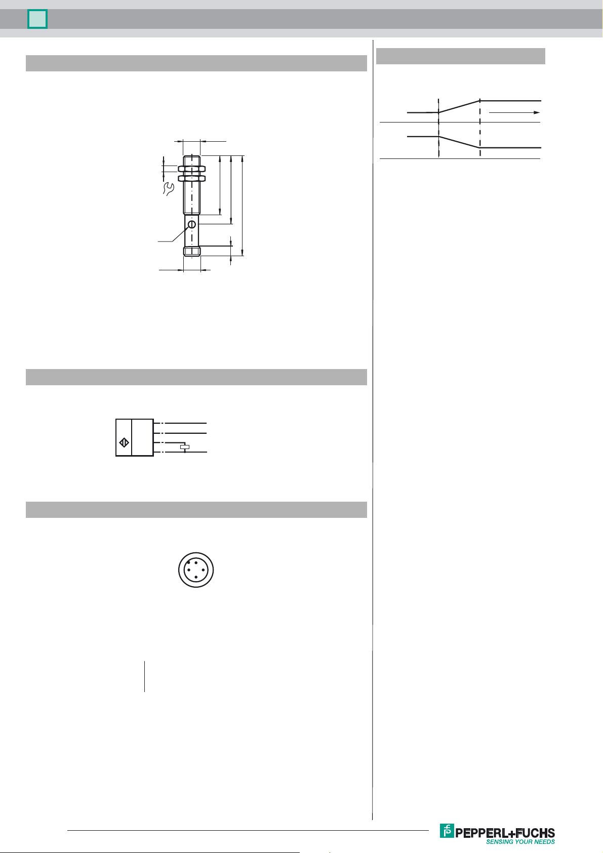
Dimensions
4
17
(Torque)
max. 10 Nm
LED
M12x1
M12x1
41
48.4
6
Additional Information
Programming the analog output mode
Rising ramp
A1 < A2:
Falling ramp
A2 < A1:
70
A1
A2
object range
A2
A1
Electrical Connection
Standard symbol/Connections:
(version I)
U
Core colors in accordance with EN 60947-5-2.
Pinout
Wire colors in accordance with EN 60947-5-2
1 BN
2 WH
3 BU
4 BK
1 (BN)
2 (WH)
4 (BK)
3 (BU)
2
1
3
(brown)
(white)
(blue)
(black)
+ U
B
Teach input
Analog output
- U
B
4
Release date: 2017-07-12 08:57 Date of issue: 2017-07-12 182235_eng.xml
Refer to “General Notes Relating to Pepperl+Fuchs Product Information”.
2
 Loading...