

Ultrasonic sensor UB2000-30GM-H3-V1
Technical data
General specifications
Sensing range 80 ... 2000 mm
Model Number
UB2000-30GM-H3-V1
Single head system
Features
• Separate evaluation
• Direct detection mode
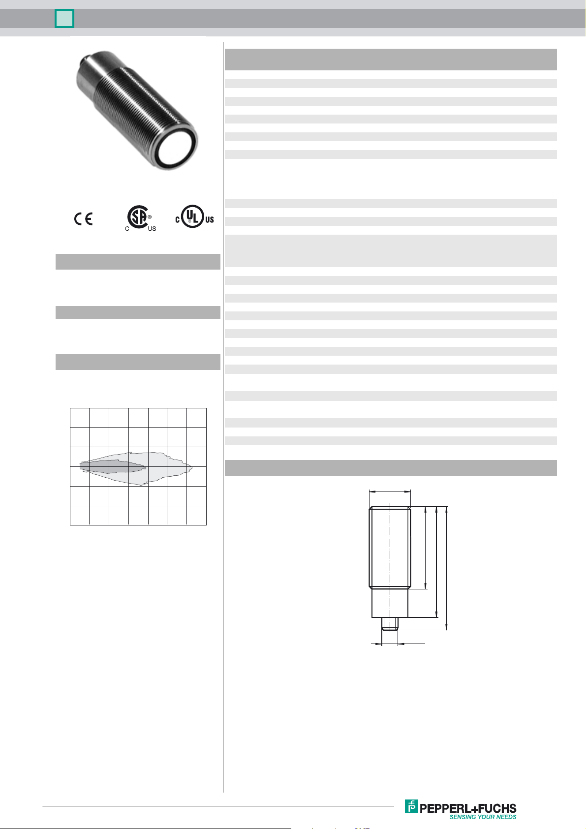
Diagrams
Characteristic response curves
Distance Y [m]
1.5
1
0.5
0
-0.5
2
1
Adjustment range 120 ... 2000 mm
Dead band 0 ... 80 mm
Standard target plate 100 mm x 100 mm
Transducer frequency approx. 180 kHz
Electrical specifications
Operating voltage U
No-load supply current I
Input
B
0
10 ... 30 V DC , ripple 10 %
≤ 30 mA
Input type 1 pulse input for transmitter pulse (clock)
0-level (active): < 5 V (U
1-level (inactive): > 10 V ... +U
0-level (active): < 1/3 U
1-level (inactive): > 2/3 U
Pulse length 20 ... 300 µs (typ. 200 µs)
Pause length ≥ 50 x pulse length
Impedance 10 kOhm internal connected to +U
Output
Output type 1 pulse output for echo run time, short-circuit proof
open collector PNP with pulldown resistor = 22 kOhm
level 0 (no echo): -U
level 1 (echo detected): ≥ (+UB-2 V)
Rated operating current I
Temperature influence the echo propagation time: 0.17 % / K
e
15 mA , short-circuit/overload protected
Ambient conditions
Ambient temperature -25 ... 85 °C (-13 ... 185 °F)
Storage temperature -40 ... 85 °C (-40 ... 185 °F)
Mechanical specifications
Connection type Connector M12 x 1 , 4-pin
Degree of protection IP67
Material
Housing nickel plated brass; plastic components: PBT
Transducer epoxy resin/hollow glass sphere mixture; polyurethane foam
Mass 140 g
Compliance with standards and
directives
Standard conformity
Standards EN 60947-5-2:2007+A1:2012
IEC 60947-5-2:2007 + A1:2012
Approvals and certificates
UL approval cULus Listed, General Purpose
CSA approval cCSAus Listed, General Purpose
CCC approval CCC approval / marking not required for products rated ≤36 V
Dimensions
M30 x 1.5
1)
SS
> 15 V)
B
(UB > 15 V)
B
(10 V < UB < 15 V)
B
... +UB (10 V < UB < 15 V)
B
2)
B
B
-1
-1.5
0 0.5 1 1.5 2 2.5 3 3.5
Curve 1: flat surface 100 mm x 100 mm
Curve 2: round bar, Ø 25 mm
Distance X [m]
M12 x 1
60
80
90
Release date: 2016-12-05 11:55 Date of issue: 2016-12-05 130473_eng.xml
Refer to “General Notes Relating to Pepperl+Fuchs Product Information”.
1
Ultrasonic sensor UB2000-30GM-H3-V1
Electrical Connection
Standard symbol/Connection:
(BN)
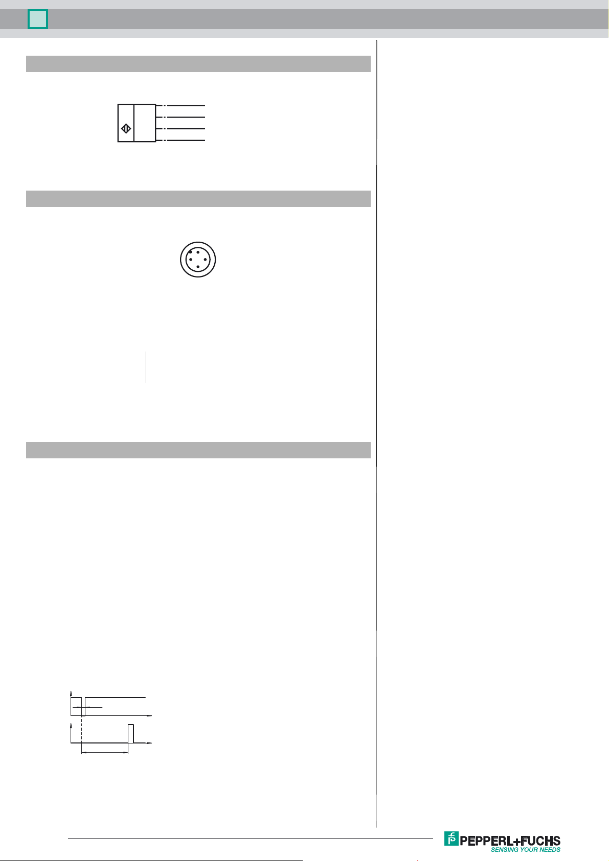
Pinout
1
2
U
2 = Emitter pulse input
4 = Echo propagation time output
Core colours in accordance with EN 60947-5-2.
(WH)
4
(BK)
3
(BU)
+ U
B
Clock
Echo
- U
B
1
2
Wire colors in accordance with EN 60947-5-2
1 BN
2 WH
3 BU
4 BK
(brown)
(white)
(blue)
(black)
4
3
Accessories
BF 30
Mounting flange, 30 mm
BF 30-F
Mounting flange with dead stop, 30 mm
BF 5-30
Universal mounting bracket for cylindrical sensors with a diameter of 5 ... 30 mm
UVW90-M30
Ultrasonic -deflector
UVW90-K30
Ultrasonic -deflector
V1-G-2M-PVC
Female cordset, M12, 4-pin, PVC cable
Function
The sensing range is determined in the downstream evaluation electronics such as
PLC modules or other existing evaluation units.
The object distance in pulse-echo mode is obtained from the echo time ∆t. The emission of an ultrasonic pulse starts simultaneously with the falling slope of the clock
input signal.
T
Clock
Echo
i
t
∆ t
t
We recommend the usage of a npn-transistor to trigger the sensors clock input. The
sensors clock input is connected to the +U
potential internally by means of a pull
B
up resistor.
2
Refer to “General Notes Relating to Pepperl+Fuchs Product Information”.
Release date: 2016-12-05 11:55 Date of issue: 2016-12-05 130473_eng.xml
 Loading...