

Pepperl Fuchs UB2000-30GM-E0-V15 Data Sheet
Ultrasonic sensor
UB2000-30GM-E0-V15
Features
• Switch output
• 5 different output functions can be set
• TEACH-IN input
• Synchronisation options
• Deactivation option
Electrical connection
Standard symbol/Connections:
(version E0, npn)
U
1
4
2
5
3
+ U
B
Switch output
Teaching input
Sync. input
- U
B
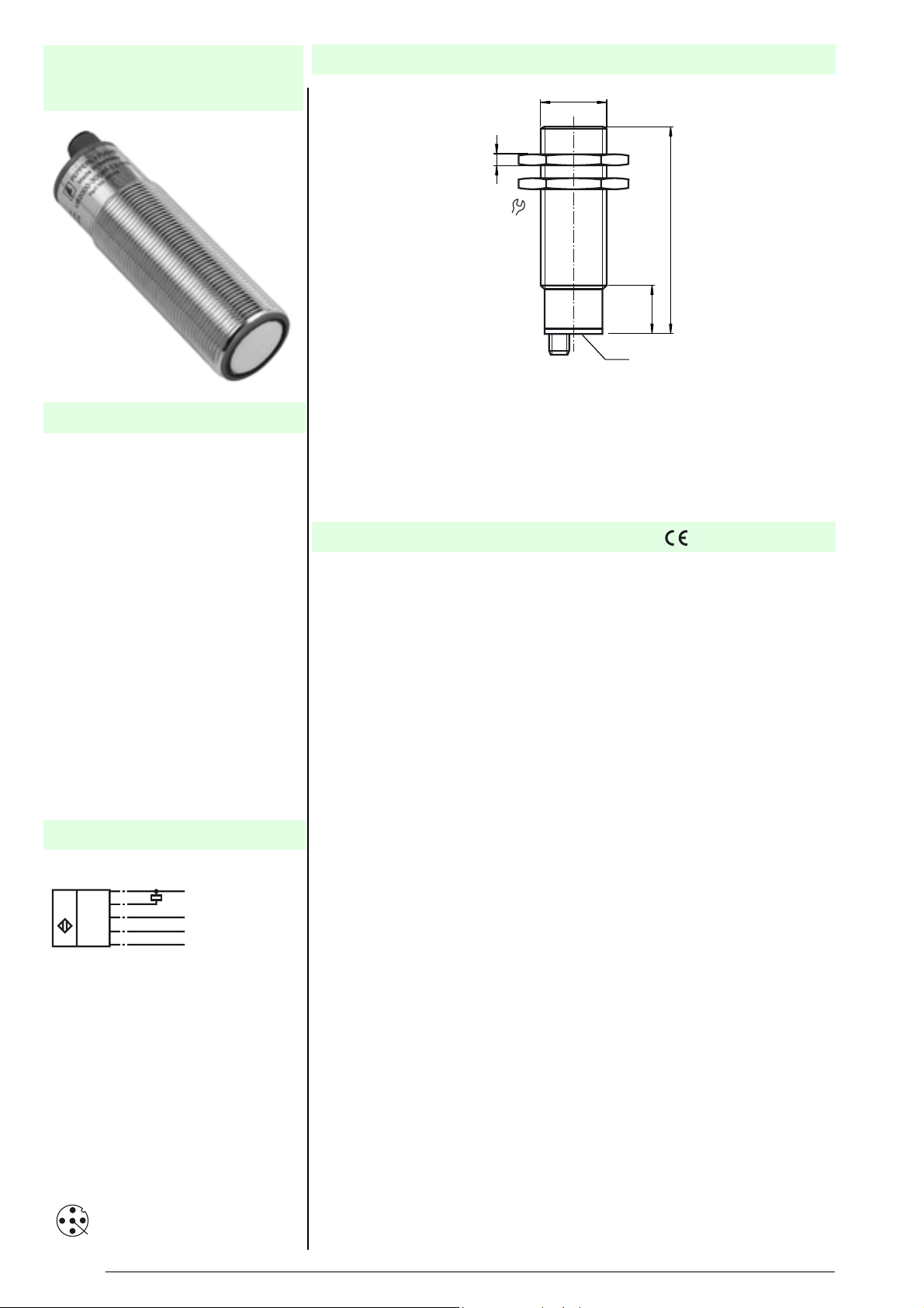
Dimensions
M30x1.5
5
36
94
22
LED
Technische DatenTechnical data
General specifications
Sensing range 200 ... 2000 mm
Unusable area 0 ... 200 mm
Standard target plate 100 mm x 100 mm
Transducer frequency approx. 175 kHz
Response delay approx. 145 ms
Indicators/operating means
LED green "Power on", TEACH-IN function object detected
LED yellow indication of the switching state, TEACH-IN function-no object detected
LED red "Error", object uncertain
Electrical specifications
Operating voltage 20 ... 30 V DC , ripple 10 %
No-load supply current I
Input
Input type 1 TEACH-IN input,
Pulse length Synchronisation pulse: ≥ 100 µs
Synchronisation frequency
Common mode operation ≤ 40 Hz
Multiplex operation ≤ 40/n Hz , n = number of sensors
Output
Output type 1 switch output E0/E1, npn, normally open/closed, programmable
Repeat accuracy ≤ 1 %
Rated operational current I
Voltage drop U
Switching frequency f max. 3.4 Hz
Range hysteresis H ≤ 1 % of the set operating distance
Temperature influence 0.17 % / K
Standard conformity
Standards EN 60947-5-2
Ambient conditions
Ambient temperature -25 ... 70 °C (248 ... 343 K)
Storage temperature -40 ... 85 °C (233 ... 358 K)
Mechanical specifications
Protection degree IP65
Connection connector V15 (M12 x 1), 5 pin
Material
Housing brass, nickel-plated, plastic components PBT
Transducer epoxy resin/hollow glass sphere mixture; polyurethane foam
Mass 145 g
d
≤ 60 mA
0
operating distance 1: -U
synchronous input
level 0: -U
Input impedance 27 kOhm
Synchronisation pulse pause: ≥ 100 µs
200 mA , short-circuit/overload protected
e
≤ 3 V
... (-UB + 1 V), level 1: (-UB + 5 V) ... +UB
B
SS
... (-UB +2 V), operating distance 2: (+UB -2 V) ... +UB 1
B
Connector V15
2
1
3
5
4
Subject to reasonable modifications due to technical advances. Copyright Pepperl+Fuchs, Printed in Germany
1
Pepperl+Fuchs Group • • • •
2005-07-27 039557_ENG.xml
HinweiseNotes BestellbezeichnungModel number
UB2000-30GM-E0-V15
Function
Synchronization
The sensor features a synchronization input for the suppression of mutual interference. It can be synchronized by applying a square wave voltage. The falling edge
of a synchro
nization pulse at the synchronization input starts a measuring cycle. A
low level > 1 s or an open synchronization input will result in the non-synchronized
normal operation of the sensor. A high level at the synchronization input disables
the sensor. Synchronization cannot be performed during TEACH-IN and vice versa.
Two operating modes are possible:
1. The sync. inputs of 2 ... 5 Sensors are connected with each other. The sensors synchronize them-
selves and operate cyclically (multiplex mode).
2. Multiple sensors can be controlled by the same synchronization signal. The sensors are synchro-
nized.
3. The synchronization pulses are sent cyclically to individual sensors. The sensors operate in mul-
tiplex mode.
n
In case of synchronized operation, the respo
se time of the sensor increases due
to a longer measuring cycle time caused by synchronization.
Note:
If the option for synchronization is not used, the synchronization input has to be connected to ground (0V) or the sensor has to
be operated via a V1 cable connector
(4-pin).
Setting the switching points
The ultrasonic sensor features a switch output with
two teachable switching points.
These are set by applying the supply voltage -UB or +UB to the TEACH-IN input.
The supply voltage must be applied to the TEACH-IN input for at least 1 s. LEDs
indicate whether the sensor has recognised the target during the TEACH-IN procedure. Switching point A1 is taught with -UB, A2 with +UB.
Five different output functions can be set:
Function TEACH-IN procedure
Window mode,
close function
- Set object to near switching point
- Teach switching point A1 with -UB
- Set object to far switching point
- Teach switching point A2 with +UB
Window mode,
open function
- Set object to near switching point
- Teach switching point A2 with +UB
- Set object to far switching point
- Teach switching point A1 with -UB
1 switching point,
close function
- Set object to near switching point
- Teach switching point A2 with +UB
- Cover sensor or remove all objects from sensing range
- Teach switching point A1 with -UB
1 switching point,
open function
- Set object to near switching point
- Teach switching point A1 with -UB
- Cover sensor or remove all objects from sensing range
- Teach switching point A2 with +UB
Detection of
ject p
ob
resence
- Cover sensor or remove all objects from sensing range
- Teach switching point A1 with -UB
- Teach switching point A2 with +UB
Characteristic curves/additional
information
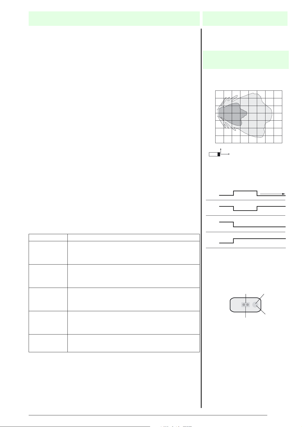
Characteristic response curve
Distance Y [m]
0.6
0.4
0.2
0.0
-0.2
-0.4
-0.6
-0.8
0.0 0.5 1.0 1.5 2.0 2.5 3.0 3.5 4.0
Y
X
Curve 1: flat surface 100 mm x 100 mm
Curve 2: round bar, Ø 25 mm
Programmed switching output function
1. Window mode, normally open function
A1 < A2:
A1
2. Window mode, normally closed function
A2 < A1:
A2
3. One switch point, normally open function
A1 -> ∞:
A2
4. One switch point, normally closed function
A2 -> ∞:
A1
5. A1 -> ∞, A2 -> ∞: Detection of object presence
Object detected: Switch output closed
No object detected: Switch output open
LED-Window
"Power on"/Disturbance
2
Dual-LED
green/red
object range
A2
A1
1
Distance X [m]
LED
yellow
Switch output
Subject to reasonable modifications due to technical advances. Copyright Pepperl+Fuchs, Printed in Germany
Pepperl+Fuchs Group • • • •
2
 Loading...