

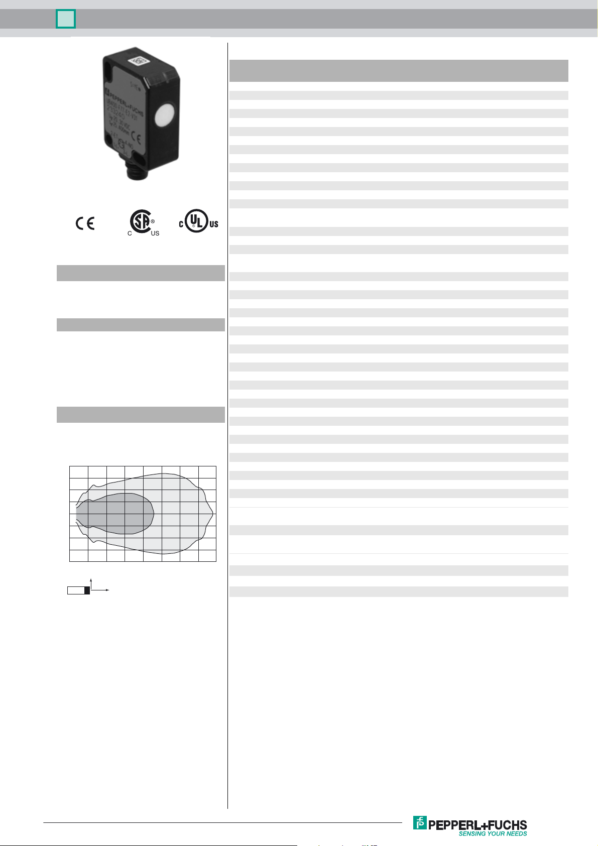
Ultrasonic direct detection sensor UB100-F77-E1-V31
Technical data
General specifications
Sensing range 10 ... 100 mm
Adjustment range 30 ... 100 mm
Dead band 0 ... 10 mm
Standard target plate 20 mm x 20 mm
Transducer frequency approx. 400 kHz
Nominal ratings
Model Number
UB100-F77-E1-V31
Ultrasonic direct detection sensor
Features
• Miniature design
• Program input
• Degree of protection IP67
• Switching status indicator, yellow
LED
Diagrams
Characteristic response curve
Distance Y [mm]
40
30
20
10
0
-10
-20
-30
-40
0 50 100 150 200 250 300 350 400
Y
X
Curve 1: flat surface 100 mm x 100 mm
Curve 2: round bar, Ø 25 mm
12
Distance X [mm]
Time delay before availability t
Limit data
Permissible cable length max. 300 m
Indicators/operating means
LED yellow switching state and flashing: Teach-In
Electrical specifications
Rated operating voltage U
Operating voltage U
No-load supply current I
Input
Input type 1 program input
Level low level : 0 ... 0.7 V (Teach-In active)
Input impedance 16 kΩ
Pulse length ≥ 3 s
Output
Output type 1 switch output E1, NPN, NC
Rated operating current I
Voltage drop U
Switch-on delay t
Repeat accuracy ± 1 mm
Switching frequency f 10 Hz
Range hysteresis H typ. 2.5 mm
Off-state current I
Temperature influence + 0.17 %/K
Ambient conditions
Ambient temperature -10 ... 50 °C (14 ... 122 °F)
Storage temperature -40 ... 85 °C (-40 ... 185 °F)
Shock resistance 30 g , 11 ms period
Vibration resistance 10 ... 55 Hz , Amplitude ± 1 mm
Mechanical specifications
Connection type M8 x 1 connector , 4-pin
Degree of protection IP67
Material
Housing Polycarbonate
Transducer epoxy resin/hollow glass sphere mixture; polyurethane foam
Installation position any position
Mass 10 g
Tightening torque, fastening screws max. 0.2 Nm
Compliance with standards and
directives
Standard conformity
Standards EN 60947-5-2:2007 + A1:2012
Approvals and certificates
UL approval cULus Listed, General Purpose
CSA approval cCSAus Listed, General Purpose
CCC approval CCC approval / marking not required for products rated
B
d
on
r
v
e
0
e
≤ 150 ms
24 V DC
20 ... 30 V DC , ripple 10 %SS ; 12 ... 20 V DC sensitivity
reduced to 90 %
≤ 20 mA
high level : U
200 mA , short-circuit/overload protected
≤ 2 V
≤ 50 ms
≤ 0.01 mA
IEC 60947-5-2:2007 + A1:2012
≤36 V
or open input (Teach-In inactive)
B
Release date: 2016-02-12 14:52 Date of issue: 2016-02-12 256271_eng.xml
Refer to “General Notes Relating to Pepperl+Fuchs Product Information”.
1
Ultrasonic direct detection sensor UB100-F77-E1-V31
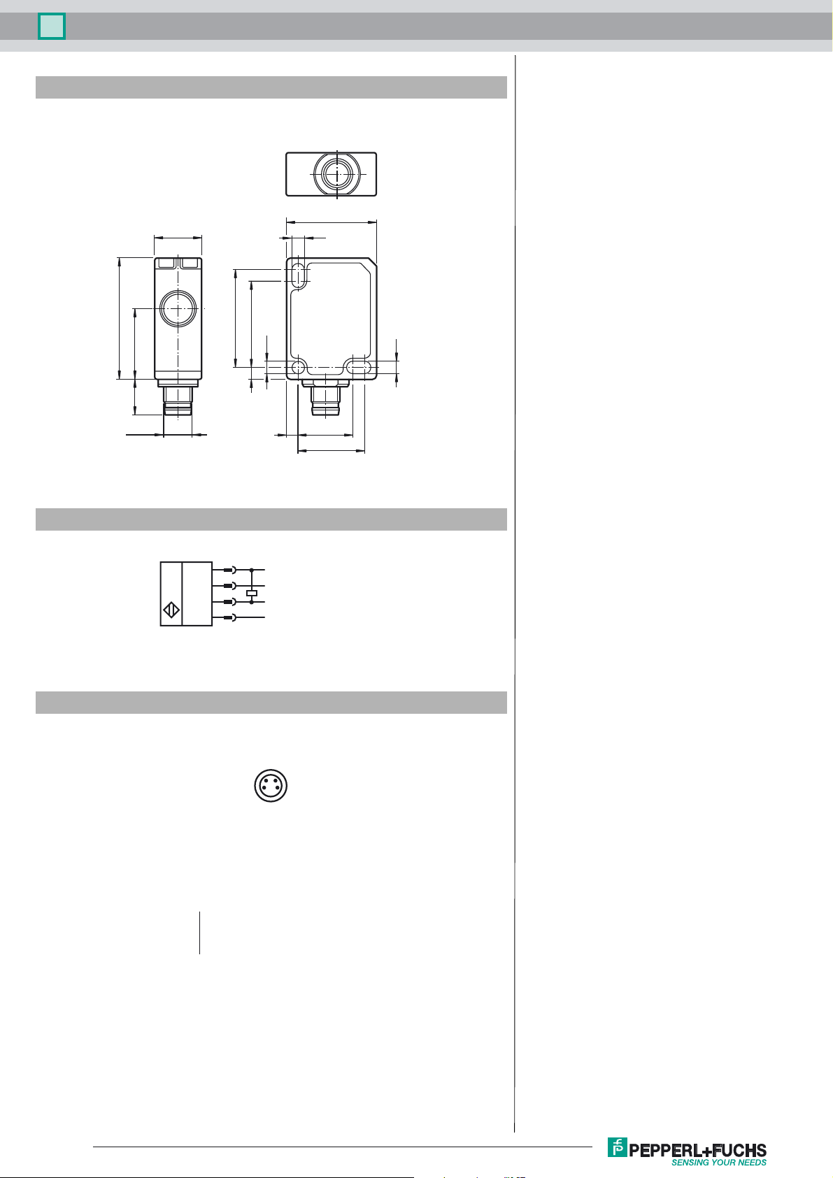
Dimensions
23
12
3.2
31
189
M8 x 1
Electrical Connection
Pinout
1
2
4
3
25
ø3.2
322
+U
ET (Teaching input)
Switching output
-U
3.2
3 14
17
B
B
24
13
Wire colors in accordance with EN 60947-5-2
1 BN
2 WH
3 BU
4 BK
Refer to “General Notes Relating to Pepperl+Fuchs Product Information”.
(brown)
(white)
(blue)
(black)
Release date: 2016-02-12 14:52 Date of issue: 2016-02-12 256271_eng.xml
2

Ultrasonic direct detection sensor UB100-F77-E1-V31
Accessories
UB-PROG4-V31
Programming unit for ultrasonic sensors with Teach-in input at pin 2
OMH-ML7-01
Mounting aid for ML7 and ML8 series, Mounting bracket
V31-GM-2M-PVC
Female cordset, M8, 4-pin, PVC cable
V31-WM-2M-PVC
Female cordset, M8, 4-pin, PVC cable
Description of Sensor Function
The ultrasonic sensor transmits ultrasonic packets in quick succession and responds to their reflection off the detected object. The sensor has
a switch output. The switching point is progammable (Teach-In). Objects beyond the taught-in switching point are not detected (background
suppression).
Teach-In of Switching Point SP
To teach in a switching point, proceed as follows:
1. Connect the sensor and turn on the operating voltage.
2. Place the object to be detected at the required distance.
3. Connect the teach-in input (ET) to -U
The LED will start flashing after 3 seconds to indicate that the sensor is ready to start the teach-in process
4. Disconnect the teach-in input (ET) with -U
(*) If no object is detected within the sensing range of the sensor, the sensor will start flashing at a faster rate. The switching point remains
unchanged.
. This can be done usingthepushbutton or the controller.
B
. The switching point SP has now been taught in
B
(*)
(*)
.
.
Switching characteristics and display LED
unusable
area
" +U
" -U
" Undefined
" = Object position
Sensing range Output LED
Adjustment range
B
B
Safety Note
The use of this device in applications, where the safety of persons depends from the devices function, is not allowed!
On
Off
Release date: 2016-02-12 14:52 Date of issue: 2016-02-12 256271_eng.xml
Refer to “General Notes Relating to Pepperl+Fuchs Product Information”.
3
 Loading...