

Signal transformer
Model Number
SU10/40a/49/116
Signal transformer
Features
• Signal converter for M4 cylindrical
housing of the KT10 series
• Light/dark switch
• Sensitivity adjuster
• Pre-fault indication
• Alignable housing
• Screw or snap mounting on mounting
rail
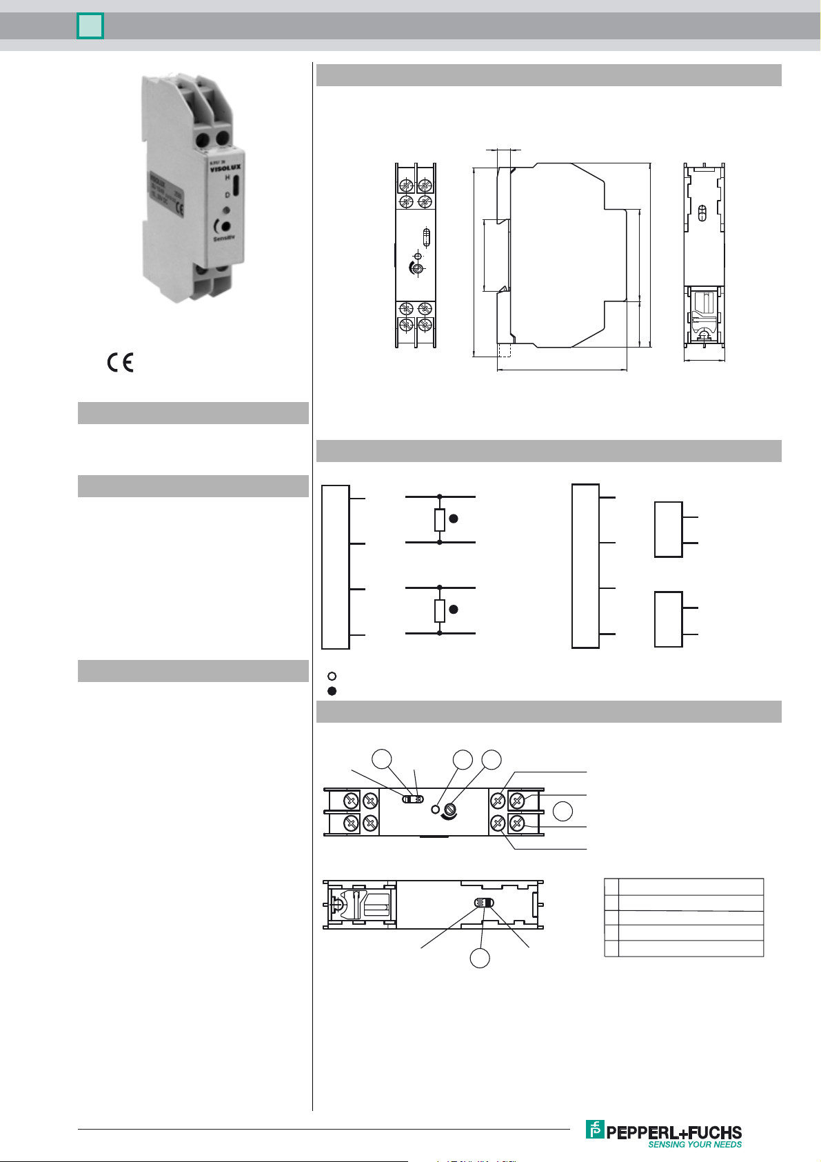
Dimensions
13
4
2
4
2
13
Electrical connection
/49
1
2
3
4
Option:
+UB
Q1
0 V
Q2
94.4
SU10/40a/49/116
5
90
WH
BK
BN/
YE
BU
4522.5
KS/KSE10
Transmitter
1
3
Receiver
2
3
18
WH
BN
BK
YE
35
58
KT10-8-*
1
2
3
4
Description
The SU10 is a signal converter for miniature
fiber-like sensors of the KT10 series.
The SU10 series features the usage of 3 different types of miniature sensors: Diffusive
mode sensor KT10-8-80, Diffusive mode with
real background suppression (BGS) sensor
KT10-8-H and through beam sensor KS/
KSE10.
= Light on
= Dark on
Indicators/operating means
LIGHT
2
13
4
1
DARK
KT10-8-80
KS10/KSE10
2
SENSITIV
5
3
2
13
4
KT10-8-H
BK
BN/YE
4
WH
BU
1 Light/Dark switch
2 Display LED yellow/green
3 Sensitivity adjuster
4 Connection Sensor
5 Changeover switsch sensor type
Release date: 2010-06-22 08:35 Date of issue: 2010-06-30 419750_ENG.xml
Subject to modifications without notice
Copyright Pepperl+Fuchs
1
Signal transformer
SU10/40a/49/116
Technical data
General specifications
Approvals CE
Indicators/operating means
Function display Yellow LED: excess gain equals 1
Controls sensitivity adjustment
Controls Light/dark switch
Electrical specifications
Operating voltage UB10 ... 30 V DC
Ripple 10 %
No-load supply current I
Output
Switching type light/dark switching
Signal output 1 NPN, 1 PNP synchronized-switching, short-circuit proof,
Switching voltage 30 V DC
Switching current 200 mA
Switching frequency f 70 Hz
Response time 5 ms
Ambient conditions
Ambient temperature -20 ... 60 °C (-4 ... 140 °F)
Storage temperature -20 ... 75 °C (-4 ... 167 °F)
Mechanical specifications
Protection degree IP40
Connection screw terminals
Material
Housing PVC
Installation DIN rail
Mass 50 g
Compliance with standards and directives
Directive conformity
EMC Directive 2004/108/EC IEC / EN 60947-5-2
Standard conformity
Shock and impact resistance IEC / EN 60068. half-sine, 50 g in each X, Y and Z directions
Vibration resistance IEC / EN 60068-2-6. Sinus. 10 -150 Hz, 5 g in each X, Y and Z
LED green: excess gain equals 3
40 mA
0
reverse polarity protected
directions
Note:
Accessories
KT10-8-H-8
Diffuse mode sensor with background
suppression
KT10-8-80
Diffuse mode sensor
KS/KSE10
Thru-beam sensor
Operation with KT10-8-80 diffusive sensor energetic:
Intended use:
The reflex light scanner contains the light transmitter and receiver in a single housing. The light from the transmitter which is reflected back from the object is evaluated
by the receiver. The detection range depends on the object colour. With dark or very
small objects the detection range reduces.
Mounting instructions:
For the operation of the SU10 in combination with the KT10-8-80, the changeover
switch on the bottom side of the SU10 must be on position: KT10
Adjustment:
Adjust the sensor on the background. If the yellow LED turns on, the detection range
needs to be reduced with the sensitivity adjuster until the yellow LED turns off.
Operation with KT10-8-H miniature diffusive sensor with real background suppression (BGS):
Intended use:
The transmitter and receiver are located in the same housing for direct target detection with background suppression. Suppression of objects outside the detection
range is achieved by arranging the angle between the transmitter and receiver (2 receiver elements).
Objects are detected independently of the structure and colour of the surface.
Mounting instructions:
For the operation of the SU10 in combination with the KT10-8-H, the changeover
switch on the bottom side of the SU10 must be on position: KT10-H
Adjustment:
Turn the sensor sensitivity to maximum with the sensitivity adjuster. The sensing
range is defined through the geometric position of the lenses within the sensor.
Subject to modifications without notice
2
Release date: 2010-06-22 08:35 Date of issue: 2010-06-30 419750_ENG.xml
Copyright Pepperl+Fuchs

Signal transformer
SU10/40a/49/116
Operation with KS/KSE10 thru-beam sensor:
Intended use:
A thru-beam sensor arrangement consists of a transmitter and receiver in separate housings.
The light of the transmitter is received by the receiver, which is installed opposite to the transmitter on a common optical axis.
The receiver evaluates if the lightpath of transmitter and receiver is interrupted by an object.
The switching behaviour is significantly dependent on object size and object opacity.
Mounting instructions:
For the operation of the SU10 in combination with the KS/KSE10, the changeover switch on the bottom side of the SU10 must be
on position: KT10
Adjustment:
By reducing the sensitivity at the sensitivity adjuster, smaller and semi opaque object may be more reliable detectable.
Release date: 2010-06-22 08:35 Date of issue: 2010-06-30 419750_ENG.xml
Subject to modifications without notice
Copyright Pepperl+Fuchs
3
 Loading...