

Page 1
SmartRunner Matcher*
Light section sensor for highprecision profile comparison
FACTORY AUTOMATION
MANUAL
Page 2

With regard to the supply of products, the current issue of the following document is ap-
plicable: The General Terms of Delivery for Products and Services of the Electrical Indus-
try, published by the Central Association of the Electrical Industry (Zentralverband
Elektrotechnik und Elektroindustrie (ZVEI) e.V.) in its most recent version as well as the
supplementary clause: "Expanded reservation of proprietorship"
SmartRunner Matcher*
Page 3

SmartRunner Matcher*
3
1 Introduction................................................................................. 5
1.1 Content of this Document ................................................................... 5
1.2 Target Group, Personnel...................................................................... 5
1.3 Symbols Used ...................................................................................... 5
2 Product Specifications............................................................... 7
2.1 Use and Application............................................................................. 7
2.2 Hazards of Laser Radiation................................................................. 9
2.3 Dimensions......................................................................................... 10
2.4 Displays and Controls ....................................................................... 10
2.5 Interfaces ............................................................................................ 12
2.6 Accessories ........................................................................................ 13
3 Installation................................................................................. 14
3.1 Storage and Disposal ........................................................................ 14
3.2 Preparation ......................................................................................... 14
3.3 Mounting the Sensor ......................................................................... 14
3.4 Electrical Connection ........................................................................ 16
3.5 Detection range.................................................................................. 19
4 Commissioning......................................................................... 20
4.1 Connecting the Sensor...................................................................... 20
5 Vision Configurator Software .................................................. 21
5.1 Connecting to Vision Configurator .................................................. 21
5.2 Application Window Structure .......................................................... 23
Page 4

4
SmartRunner Matcher*
5.3 Menu Bar .............................................................................................24
5.3.1 File Menu ......................................................................................... 24
5.3.2 View Menu ....................................................................................... 24
5.3.3 Sensor Menu....................................................................................25
5.3.4 Image Menu ..................................................................................... 25
5.3.5 Administration Menu ........................................................................26
5.3.6 Help Menu........................................................................................ 26
5.4 Toolbar.................................................................................................27
5.5 Sensor Data.........................................................................................28
5.6 Image Display .....................................................................................28
5.7 Configuration window........................................................................33
5.7.1 Sensor Information........................................................................... 33
5.7.2 Common Tab.................................................................................... 34
5.7.3 Matcher Tab .....................................................................................36
6 Operation................................................................................... 41
6.1 Configuration Mode............................................................................41
6.2 Code Card Mode.................................................................................47
6.2.1 Setting Device Parameters via Control Code.................................... 48
6.3 Presentation Mode .............................................................................49
6.4 Runtime Mode.....................................................................................50
6.4.1 Communication via the RS-485 Interface ......................................... 50
7 Maintenance and Repair.......................................................... 54
7.1 Maintenance........................................................................................ 54
7.2 Repair ..................................................................................................54
8 Troubleshooting........................................................................ 55
8.1 What to Do in Case of a Fault ............................................................55
9 License Note ............................................................................. 57
Page 5
SmartRunner Matcher*
Introduction
2018-01
5
1 Introduction
1.1 Content of this Document
This document contains information required to use the product in the relevant phases of the
product life cycle. This may include information on the following:
Product identification
Delivery, transport, and storage
Mounting and installation
Commissioning and operation
Maintenance and repair
Troubleshooting
Dismounting
Disposal
The documentation comprises the following parts:
This document
Datasheet
In addition, the documentation may comprise the following parts, if applicable:
EU-type examination certificate
EU declaration of conformity
Attestation of conformity
Certificates
Control drawings
Instruction manual
Other documents
1.2 Target Group, Personnel
Responsibility for planning, assembly, commissioning, operation, maintenance, and
dismounting lies with the plant operator.
Only appropriately trained and qualified personnel may carry out mounting, installation,
commissioning, operation, maintenance, and dismounting of the product. The personnel must
have read and understood the instruction manual and the further documentation.
Prior to using the product make yourself familiar with it. Read the document carefully.
1.3 Symbols Used
This document contains symbols for the identification of warning messages and of informative
messages.
Note!
Visit www.pepperl-fuchs.com to access further documentation for full information about the
product.
Page 6
2018-01
6
SmartRunner Matcher*
Introduction
Warning Messages
You will find warning messages, whenever dangers may arise from your actions. It is
mandatory that you observe these warning messages for your personal safety and in order to
avoid property damage.
Depending on the risk level, the warning messages are displayed in descending order as
follows:
Informative Symbols
Action
This symbol indicates a paragraph with instructions. You are prompted to perform an action or
a sequence of actions.
Danger!
This symbol indicates an imminent danger.
Non-observance will result in personal injury or death.
Warning!
This symbol indicates a possible fault or danger.
Non-observance may cause personal injury or serious property damage.
Caution!
This symbol indicates a possible fault.
Non-observance could interrupt the device and any connected systems and plants, or result in
their complete failure.
Note!
This symbol brings important information to your attention.
Page 7
SmartRunner Matcher*
Product Specifications
2018-01
7
2 Product Specifications
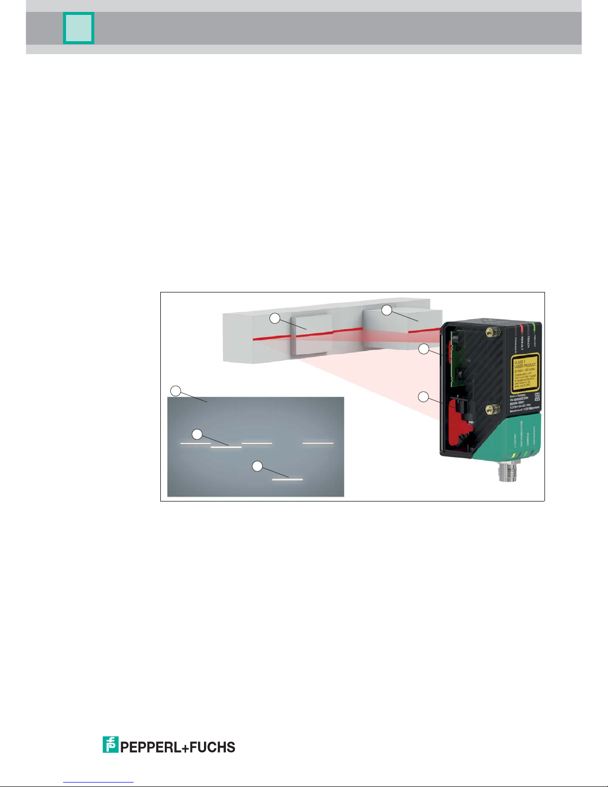
2.1 Use and Application
This manual applies to the light section sensors VLM350-F280-2E2-1000, VLM350-F280-R41001 and VLM350-F280-R4-1101 (hereafter referred to as
sensor). The sensor compares
cu
rrent height profiles with a previously taught-in height profile. The sensor is based on
SmartRunner technology and combines the light section method for detecting height profiles
with a 2-D vision sensor.
An emitter optic is used to project a laser line onto an object as part of the light section method.
This is detected by a camera at a specific angle. A height and width profile is created using the
triangulation principle. This laser technology provides reliable measurements on different
surfaces.
The sensor is commissioned and operated using the Vision Configurator software. In addition,
preset parameters can be transferred to the sensor via Data Matrix control codes. In this way
you have the opportunity to quickly adapt the settings to the conditions of the measuring
environment and the measuring object without using a laptop in case of replacement.
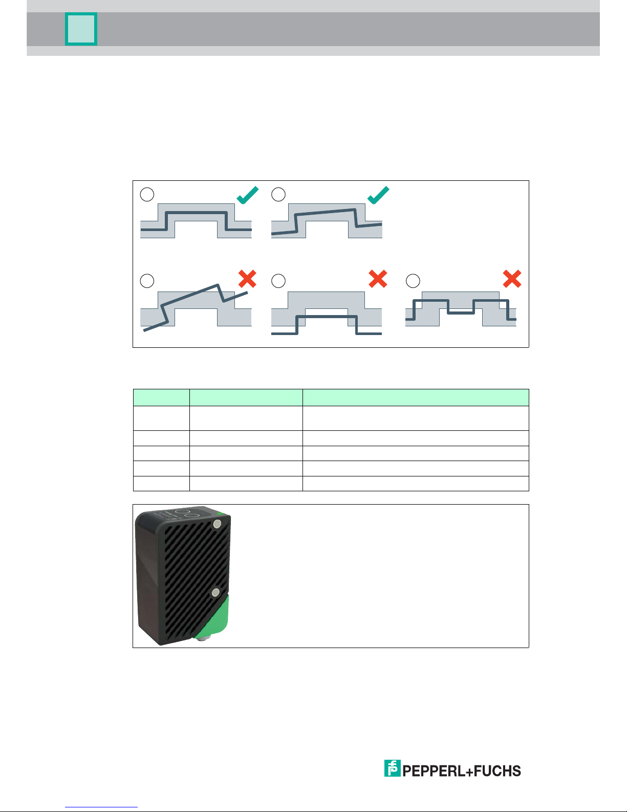
Structure of the sensor
Figure 2.1 Overview of components and measurement result
The SmartRunner has an optimized hardware and software platform. It is available in different
versions for specific applications. The device is certified according to laser protection class 1.
Features of the sensor
The sensor, optimized and pre-configured for comparing height profiles, offers protection from
damage and from the production of rejects. An object is identified by comparing with stored
reference profiles, which detects whether the object is in the correct position. This means
gripping processes, such as in robotics, are always accurate.
1 Flat profile
2 Raised profile
3 Emitter optic (vision sensor including LED lighting)
4 Camera
5 Height profile on the image sensor (measuring result)
1
1
2
2
3
4
5
Page 8
2018-01
8
SmartRunner Matcher*
Product Specifications
The integrated control interface of the sensor has been optimized by the factory to report
deviations from a previously programed contour. Via the profile comparison, the sensor
detects the recorded contour of an object, its correct location, and spacing. In case of a fault,
collisions and damage are safely eliminated and lengthy machine downtimes are therefore
avoided.
For this, the sensor is taught in to a specific height profile and a trigger executes a
reconciliation between the currently-recorded contour and the reference contour. A "good"
signal is produced if these are identical. If the two profiles differ, a "Bad" signal is produced.
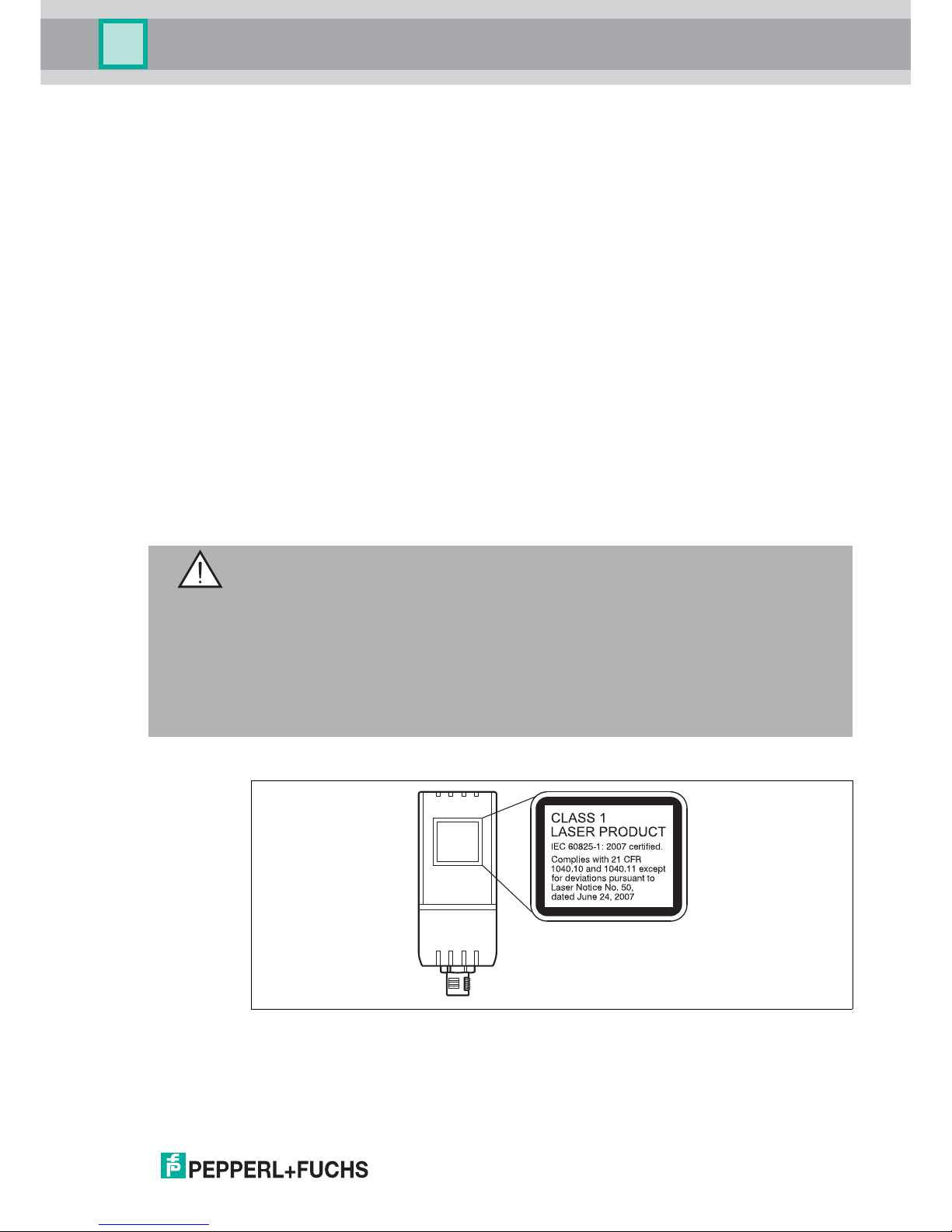
Figure 2.2 Capturing object contour, position, and distance
Figure 2.3 Sensor
Position Designation Function
1 Good-signal-scenario 1 Taught-in reference contour with adjustable
tolerance range
2 Good-signal-scenario 2 Slight torsion within the tolerance range
3 Bad-signal-scenario 3 Excessive torsion outside the tolerance range
4 Bad-signal-scenario 4 Too great a distance between sensor and object
5 Bad-signal-scenario 5 Incorrect or faulty object detected
2
1
3 54
Page 9
SmartRunner Matcher*
Product Specifications
2018-01
9
Parameterization and Operating Modes
The laser-line triangulation sensor can be configured or parameterized via 3 different methods.
Reading in code cards via the sensor camera
Processing configuration telegrams via the bus interface
Using the Vision Configurator software
The sensor has different operating modes, which can be activated for configuration,
presentation, or normal operation.
Runtime mode: measurement mode, sensor works as configured
Configuration mode: mode for configuring the sensor via data telegrams and via the
Vision Configurator configuration program
Code card mode: mode for configuring the sensor via Data Matrix control codes without
the assistance of a PC
Presentation mode: mode for presentation or testing without the assistance of a PC
2.2 Hazards of Laser Radiation
This section describes the contents and location of the warning label.
The sensor used corresponds to the safety standard IEC 60825-1:2007 for a laser class 1
product. In addition, the US regulation 21 CFR 1040.10 and 1040.11 is fulfilled except for
Laser Notice No. 50 dated June 24, 2007.
The warning label is fixed to the back of the housing as shown in the following figure.
Figure 2.4 Laser radiation warning message
Warning!
Class 1 laser light
The laser light can be an irritant, especially in a dark environment. Do not point lasers at
people!
Never look into the laser beam port if the sensor is operating.
Maintenance and repairs must be carried out by authorized service personnel only!
Install the device so that the warning is clearly visible and legible.
Do not remove the sensor's protective cover.
Page 10
2018-01
10
SmartRunner Matcher*
Product Specifications
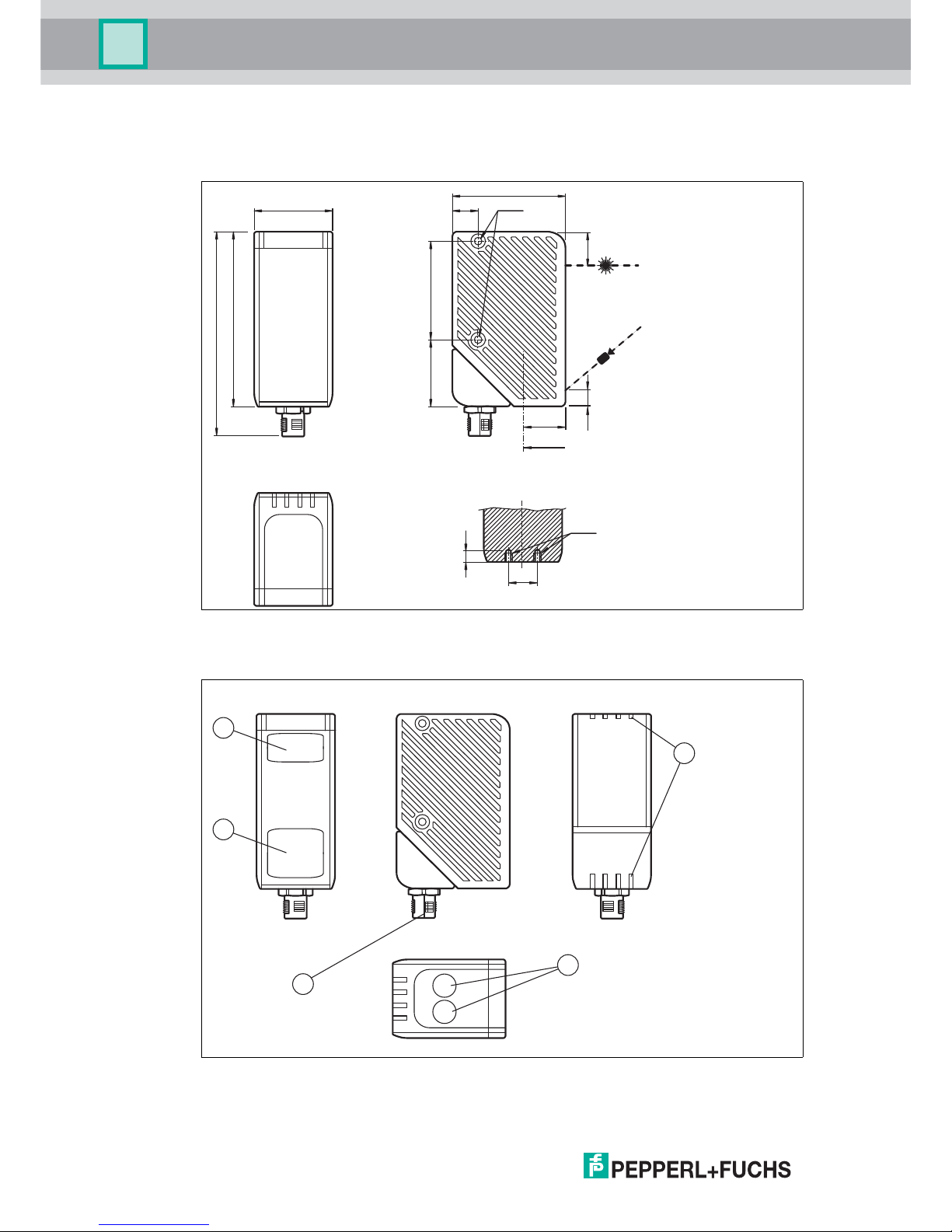
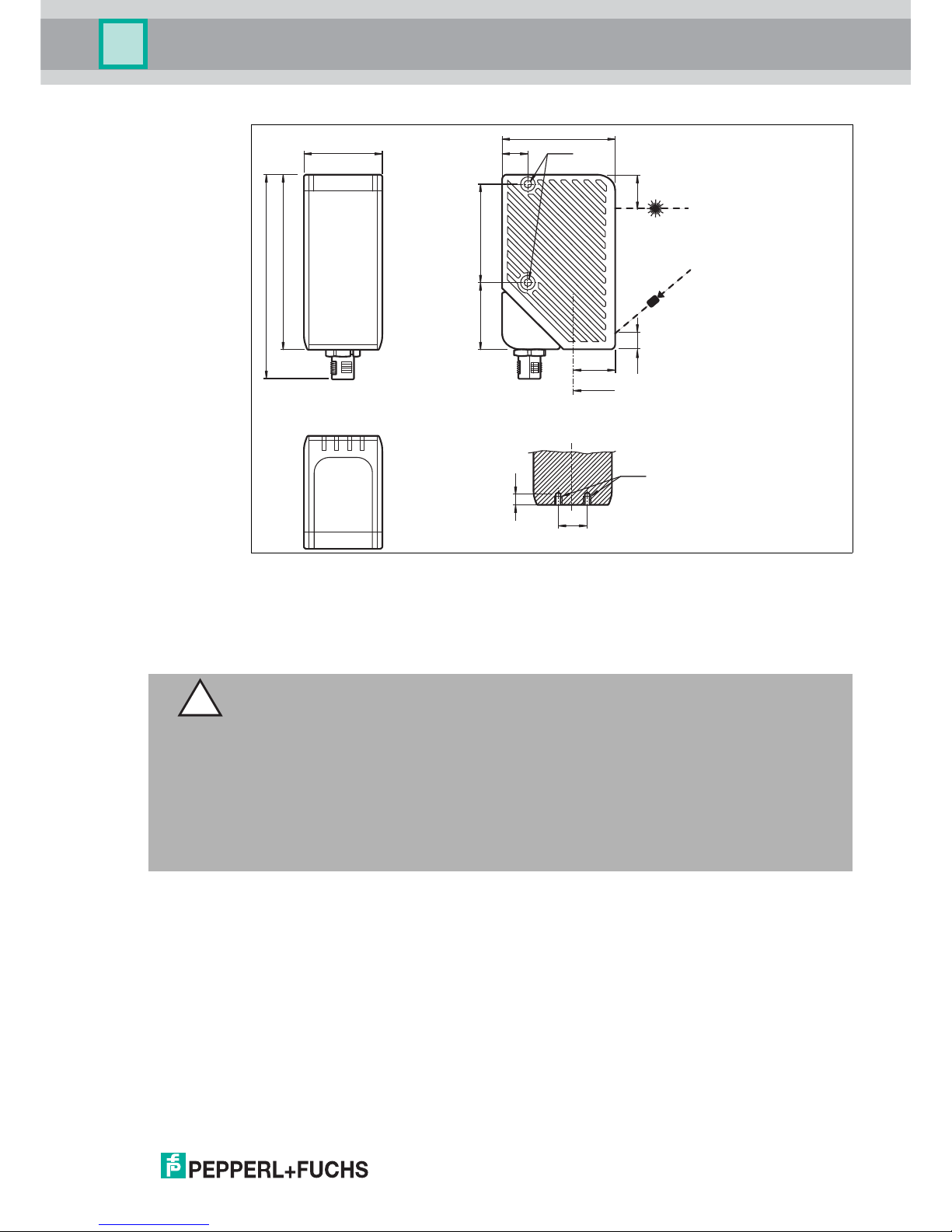
2.3 Dimensions
The devices in the SmartRunner series have the following identical housing dimensions.
Figure 2.5 Dimensions of the SmartRunner series
2.4 Displays and Controls
Figure 2.6 Overview of displays and controls
38 12 M4
55
85
99.1
32 48
5
8 15.35
M4
20
A
A
14
1
3
4
2
12
5
Page 11
SmartRunner Matcher*
Product Specifications
2018-01
11
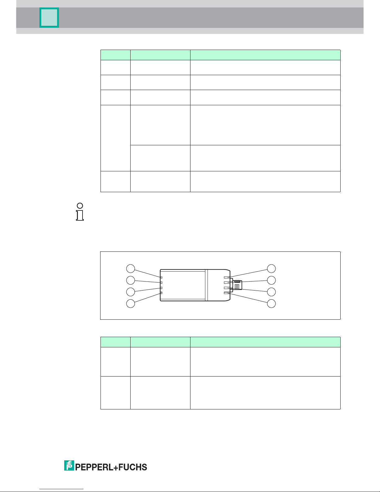
Description of the LEDs
Figure 2.7 LEDs overview
Position Designation Function
1 Emitter optic
protective cover
Is used to protect against damage and contamination
2 Reception optic
protective cover
Is used to protect against damage and contamination
3 LEDs The functional description for the LEDs can be found in
the table below.
4 Function keys in
Presentation mode
Function key 1: triggers an evaluation
Function key 2: when pressed and held for 2 seconds,
activates the teach-in process. When pressed and
held for longer than 2 seconds, activates Code Card
mode
Function keys in
Runtime mode
Function key 1: no function
Function key 2: when pressed and held for longer than
2 seconds, activates Code Card mode
5 Electrical Connection The sensor is connected electrically via a MAIN 8-pin M12
connector plug on the bottom of the housing. See chapter
3.4.
Note!
The function keys are only activated during a parameterizable time span after the sensor is
switched on, after which they are locked. The default value for this time span is 5 minutes.
The function keys have different functions depending on the selected operating state.
Position Designation Function
1 Ready (green/red) Lights up red if there is a sensor fault
Lights up green when the sensor is ready for operation
Flashes green if the sensor is in Configuration mode
2 Match 3/4
(green/yellow)
Lights up green if the scanned profile matches the
taught-in profile 3 (MATCH 3)
Lights up yellow if the scanned profile matches the
taught-in profile 4 (MATCH 4)
2
1
5
6
7
8
4
3
Page 12
2018-01
12
SmartRunner Matcher*
Product Specifications
2.5 Interfaces
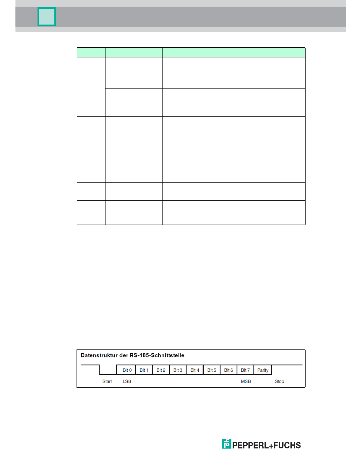
The RS-485 Interface
The reader is equipped with an RS-485 interface for communication purposes, i.e.,
parameterizing the reader functions or reading out current process data during operation. This
interface is operated in 8-E-1 operating mode and fitted with a terminator that can be activated
or deactivated by parameterizing the sensor head.
The RS-485 interface supports the following transfer rates:
38400 bit/s
57600 bit/s
76800 bit/s
115200 bit/s (default value)
230400 bit/s
Data structure of the RS-485 interface
3 Result (green/red) Lights up green if a scanned profile matches a taught-
in profile
Lights up red if a scanned profile does not match a
taught-in profile
Applies in Code Card
mode
Lights up green when a correct code has been read
Lights up red when an incorrect code has been read
Off if no code has been read
4 Match 1/2
(green/yellow)
Lights up green if the scanned profile matches the
taught-in profile 1 (MATCH 1)
Lights up yellow if the scanned profile matches the
taught-in profile 2 (MATCH 2), optional
5 Diagnosis (red) Lights up red if a bus error has occurred
Lights up red if a system error has occurred on the
interface controller
Flashes red if the sensor is in Update mode
6 POWER (green) Lights up as soon as voltage is present
Flashes in Configuration mode
7 Teach in (yellow) Lights up yellow during the teach in process
8 TRIGGER (yellow) Lights up yellow if the hardware trigger signal is
activated
Position Designation Function
Page 13
SmartRunner Matcher*
Product Specifications
2018-01
13
2.6 Accessories
Other accessories can be found online at www.pepperl-fuchs.com.
Order designation Description
V19-G-5M-PUR-ABG Single-ended female cordset, M12, 8-pin, shielded, PUR
cable
VLX-MB1 Mounting aid, adaptable 360° adjustment of mounting head
and mounting foot
VLX-MB2 Mounting aid, fixing bracket
PCV-USB-RS485 Converter
Set
USB to RS 485 interface converter
Page 14
2018-01
14
SmartRunner Matcher*
Installation
3Installation
3.1 Storage and Disposal
Keep the original packaging. Always store and transport the device in the original packaging.
Store the device in a clean and dry environment. The permitted ambient conditions must be
considered, see datasheet.
Disposing of device, packaging, and possibly contained batteries must be in compliance with
the applicable laws and guidelines of the respective country.
3.2 Preparation
Unpacking the unit
1. Check that all package contents are present and undamaged.
If anything is damaged, inform the shipper and contact the supplier.
2. Check that all items are present and correct based on your order and the shipping
documents.
If you have any questions, please contact Pepperl+Fuchs.
3. Keep the original packing material in case you need to store or ship the unit at a later time.
3.3 Mounting the Sensor
The operating distance differs depending on the sensor. The correct operating distance can be
found in the datasheet for the sensor to be installed.
The following illustration shows all the relevant housing dimensions in mm:
Note!
Mounting an optical device
Do not aim the sensor at the sun.
Protect the sensor from direct long-term exposure to sun.
Prevent condensation from forming by not exposing the sensor to any major fluctuations
in temperature.
Do not expose the sensor to the effects of any aggressive chemicals.
Keep the lenses and reflector of the device clean. Clean with a soft cloth, using standard
commercial glass cleaner if necessary.
We recommend to clean the optical surface and to check screw fittings and electrical
connections at regular intervals.
Page 15
SmartRunner Matcher*
Installation
2018-01
15
Figure 3.1 Space requirements
The surface must be level to prevent the housing from becoming misaligned when the fittings
are tightened. We advise securing the screws with spring disks to prevent the sensor
becoming misaligned. Following installation of the sensor, ensure that there is still sufficient
space to connect the connection cable to the sensor
Mounting the Housing
The device has 2 M4 threads on the base and on both sides of the housing to allow easy
installation of the sensor in your plant. This means there are 3 different ways to mount the
sensor in your plant.
One-sided lateral mounting with M4 screws: You can mount the housing on its right-hand
or left-hand side using the 2 M4 threaded sleeves. The maximum screw-in depth of the
M4 screws is 8 mm.
Continuous lateral mounting with M3 screws: M4 threaded sleeves are designed in such
a manner that M3 screws pass all the way through the housing. Use 2 sufficiently long M3
screws with 2 lock nuts to mount the device in the plant
38 12 M4
55
85
99.1
32 48
5
8 15.35
M4
20
A
A
14
Caution!
Damage to the equipment caused by improper installation!
Device components can be damaged if the permissible screw-in depths and the maximum
permissible tightening torque is exceeded.
Note that the threads on the bottom of the housing are not thru–holes.
Observe the maximum permissible screw-in depth to avoid damaging the device or mounting
incorrectly.
Never exceed the maximum permissible tightening speed of the fixing screws. The maximum
tightening torque of the mounting screws must not exceed 2 Nm.
Page 16
2018-01
16
SmartRunner Matcher*
Installation
Mounting on the underside of the device with M4 screws: You can use the 2 threaded
sleeves to mount the housing on the underside of the device. The maximum screw-in
depth of the M4 screws is 5 mm.
Positioning the Sensor
When positioning the sensor, ensure that the camera's field of vision is not obscured by the
objects being scanned.
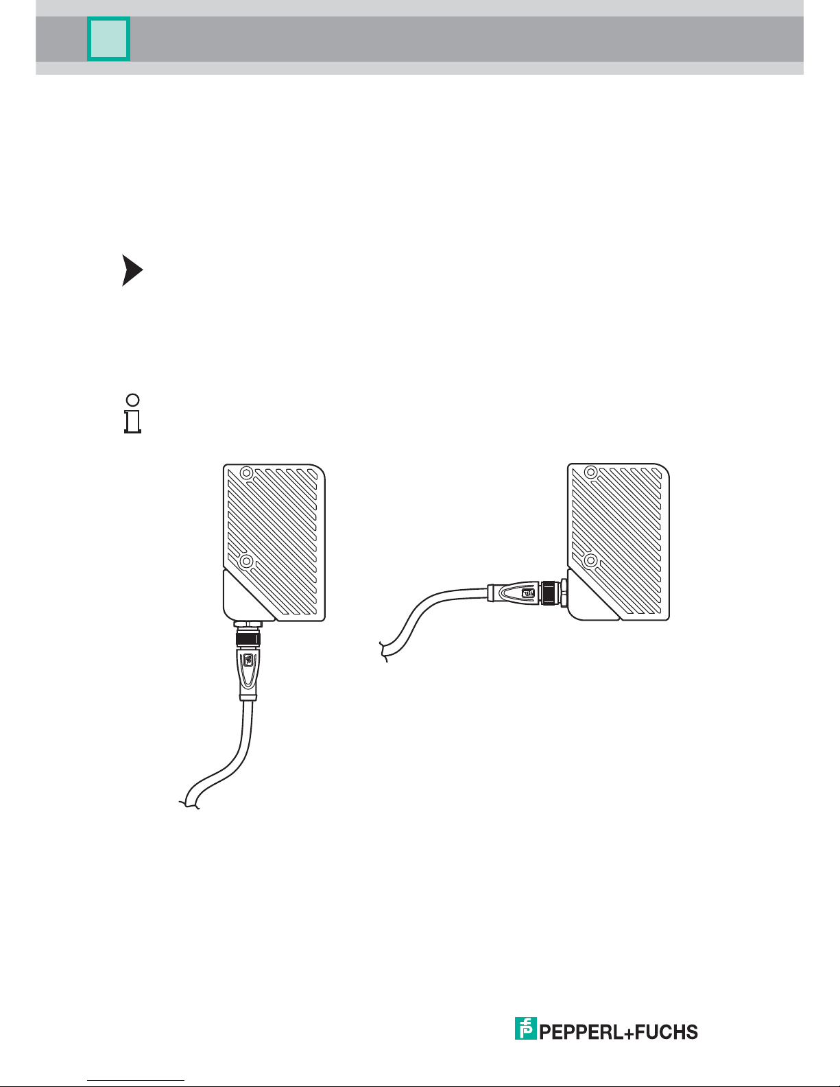
3.4 Electrical Connection
Connecting the Supply Voltage
The sensor is connected electrically via a MAIN 8-pin M12 connector plug on the bottom of the
housing. The power supply and data transfer take place via this connection. To connect the
sensor, proceed as follows:
1. Plug the 8-pin M12 socket into the plug on the bottom of the housing.
2. Screw the lock nut onto the connector as far as it will go. This ensures that the power cable
cannot be pulled out inadvertently.
Tip
The corner of the housing where the MAIN 8-pin M12 connector plug is located can be rotated.
Depending on the mounting position, you can rotate the connector plug in a different direction
to ensure simple cabling.
Figure 3.2 M12 connector plug
Page 17
SmartRunner Matcher*
Installation
2018-01
17
Figure 3.3 Connection layout
Pepperl+Fuchs single-ended female cordsets are manufactured in accordance with EN609475-2. When using a V19-G-5M-PUR-ABG single-ended female cordset with an open cable end,
connector pins are assigned as follows:
Pin Wire color Signal Description
1 white IN trigger Trigger input. Triggers an evaluation, if the
sensor is in continuous evaluation mode
(independent)
2 brown +UB + 24 V power supply
3 green Data+ RS-485 RS-485 interface: Data +
4 yellow Data- RS-485 RS-485 interface: Data -
5 gray Teach Control signal for teaching in the background
line
6 pink Good Output 1 is set if the height profile detected
matches the taught-in profile in terms of form
and position.
Once the teach-in process has been
performed, this output signals that teach-in
was successful
7 blue GND Ground for the + 24 V power supply
8 red Bad Output 2 is set if:
No object has been detected
or
The form detected does not match the
taught-in form
or
The position detected is outside the
tolerance.
Once the teach-in process has been
performed, this output signals that teach-in
has not been successful
1
4
6
7
8
5
3
2
Page 18
2018-01
18
SmartRunner Matcher*
Installation
Connection using the RS-485 Interface
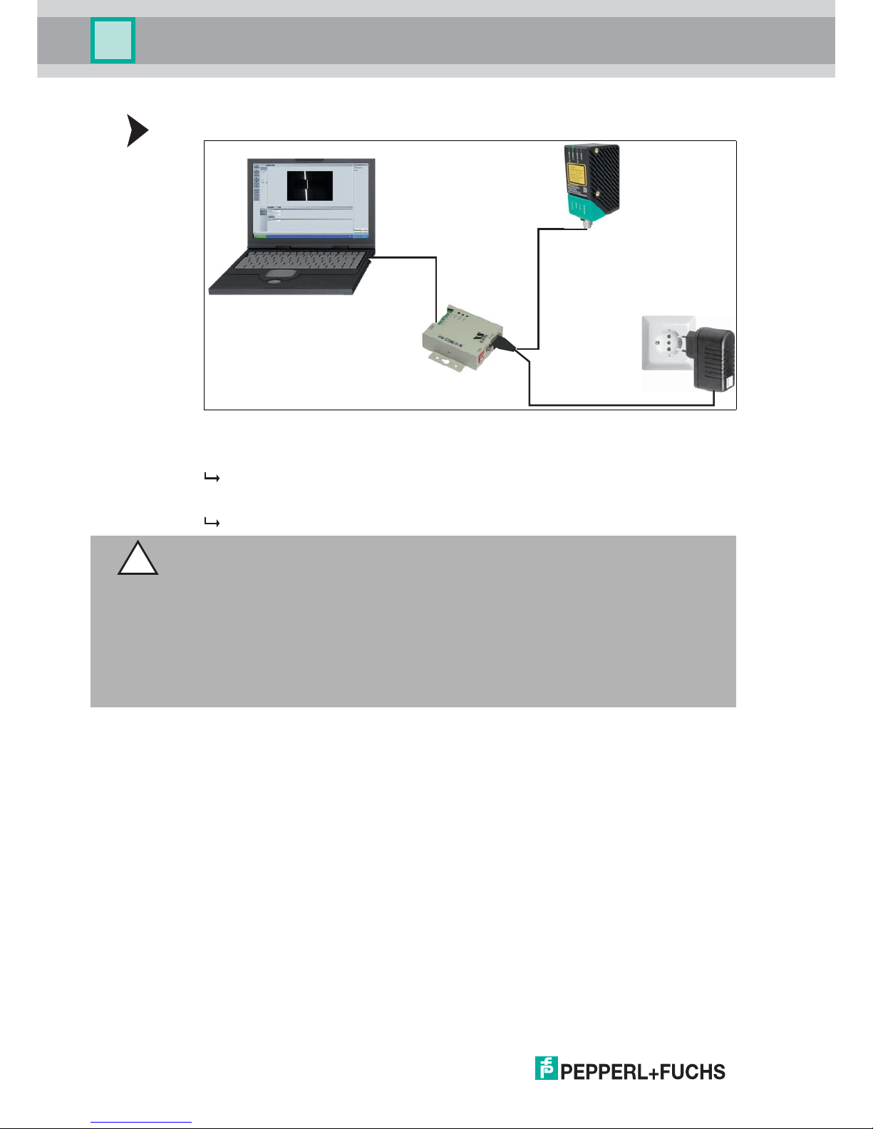
Figure 3.4 PCV-USB-RS-485 Converter Set
1. Plug a plug-in power supply into a socket and connect it to the interface converter.
The indicator LEDs on the sensor light up.
2. Establish a USB connection between the PC system and interface converter.
The PWR LED on the interface converter lights up red.
Shielding Cables
The shielding of connection lines is required to suppress electromagnetic interference.
Establishing a low resistance or low impedance connection with the protective conductor or
equipotential bonding circuit is a particularly important factor in ensuring that these
interference currents do not become a source of interference themselves. Only use connection
lines with braid. Avoid connection lines with foil shield because this would increase the line
capacities. The shielding is integrated at both ends, i.e., in the switch cabinet, on the control
panel, and on the reader. The grounding terminal available as an accessory allows easy
integration in the equipotential bonding circuit.
In exceptional cases, the shielding of a connection at one end may be more favorable if:
An equipotential bonding cable is not laid or cannot be laid.
A film shield is used.
The following points relating to shielding must also be noted:
Use metal cable clips that cover large areas of the shield.
After installing the cable shield in the control cabinet, place it directly on the equipotential
bonding rail.
USB
110 V / 230 V
24 V DC
RS 485
Caution!
Damage to the device
Connecting an alternating current or excessive supply voltage can damage the device or
cause the device to malfunction.
Electrical connections with reversed polarity can damage the device or cause the device to
malfunction.
Connect the device to direct current (DC). Ensure that the supply voltage rating is within the
specified device range. Ensure that the connecting wires on the female cordset are connected
correctly.
Page 19

SmartRunner Matcher*
Installation
2018-01
19
Direct the protective grounding connections to a common point in a star configuration.
The cross-section of the cables used for grounding should be as large as possible.
Additional Ground Connection
3.5 Detection range
Figure 3.5 Detection range
Note the detection range of the SmartRunner Matcher when planning your plant. You will find
more information on the detection range in the following table.
Order designation Description
PCV-SC12 Clip for mounting an additional ground
connection.
PCV-SC12A
1 Field of view
Detection range X Distance Z to the sensor
min 40 mm 60 mm
max 160 mm 350 mm
max
X
min
X
max
min
Z
Z
1
Note!
The smallest possible resolution in the X and Z direction increases on a linear basis to the
distance Z to the sensor.
Page 20

2018-01
20
SmartRunner Matcher*
Commissioning
4 Commissioning
4.1 Connecting the Sensor
The sensor is configured using the Vision Configurator software. You have the opportunity to
carry out settings on the sensor directly using the Vision Configurator software.
Aligning the Sensor
Use the image display and diagram display in the Vision Configurator software to optimally
align the sensor.
1. Power the reader via the 24 VDC socket on the device.
2. Use the automatic exposure time control to set an appropriate exposure value.
If exposure time control was successful, the result LED will light up green.
3. Align the sensor so that a complete line that is as narrow as possible can be seen in the
image display.
The optimal reading distance between the sensor and the measurement object is set.
Page 21

SmartRunner Matcher*
Vision Configurator Software
2018-01
21
5 Vision Configurator Software
The sensor is commissioned and operated using the Vision Configurator software.
The Vision Configurator software makes it easy to operate the sensor with its user-friendly
interface. Standard functions include making connections to the sensor, specifying the
operating parameters, saving data sets, and displaying data and error diagnostics.
User Rights and Password
Establishing a Network Connection
To establish a network connection with the sensor, proceed as follows:
1. Supply the sensor with power.
2. Start the Vision Configurator software.
3. Enter your user name and password.
5.1 Connecting to Vision Configurator
Connect Vision Configurator
Connect the SmartRunner to a PC.
Note!
The following user roles are predefined with different authorizations in the Vision Configurator.
User rights Description Password
Default View all information
Sensor configuration
Create users at same or lower level
A password is not required
User View all information
Sensor configuration
Create users at same or lower level
User
Admin View all information
Sensor configuration
Request the admin
password from
Pepperl+Fuchs
Table 5.1 The users have different access and administration rights depending on the respective
user role.
Note!
Additional steps for user-defined installation and installation of additional components are
described in the Vision Configurator manual. The Vision Configurator manual can be found
online at www.pepperl-fuchs.com.
Note!
Use a suitable RS-485/USB connecting cable and an adapter cable to do this:
Function Order designation
USB interface converter to RS-485 including
cable unit with power supply
PCV-USB-RS485-Converter Set
Cable unit with power supply for USB/RS-485
interface converter
PCV-KBL-V19-STR-RS485
Page 22

2018-01
22
SmartRunner Matcher*
Vision Configurator Software
Figure 5.1 Home screen
Wizard - Operation assistant for Vision Configurator
The Wizard complements the Vision Configurator configuration software. Double-click on the
Wizard button to launch the operation assistant. You will be guided step-by-step through the
individual settings.
Proceed as follows to launch the Vision Configurator.
Starting Vision Configurator
1. Select the 2-D/3-D button on the "Sensor Family" tab.
2. Select SMARTRUNNER in the "parameter range" with connection type RS485.
3. Select the required COM port.
4. In the Baud rate window ensure that the value 115,200 is set. Otherwise select the value.
5. In the Head address window, ensure that the address is set to Address 0. Otherwise
select the address.
6. Use the OK button to confirm your settings.
The application window will open.
Page 23

SmartRunner Matcher*
Vision Configurator Software
2018-01
23
5.2 Application Window Structure
The application screen opens after you log in.
The software is designed to be similar to most Windows applications.
Note!
The individual functions depend on the type of sensor connected and the current authorization
level, so they are not always all visible.
1 Title bar Shows the IP address, the software name, and the
version number
Contains the Minimize/Maximize/Close buttons
2 Menu bar Displays all the menus in the program
Provides an overview and helps with navigation
3 Sensor data screen Displays data for the connected sensor
4 Sensor output screen Shows the log display
5 Status bar Displays status information about the application
6 Configuration window Contains the sensor-specific parameters that you
can set
7 Toolbar Contains icon buttons as an extension to the menu
8 Check boxes Show images: Enables or disables the image
display
Show results: Enables or disables the results area
9 Results area Displays results from the sensor
A varying number of tabs can be displayed
depending on which sensor is connected
This field can be enabled or disabled via Show
results
1
2
3
4
5
6
7
8
10
11
9
Page 24

2018-01
24
SmartRunner Matcher*
Vision Configurator Software
5.3 Menu Bar
The menu bar contains a list of menu items. The functionality depends on the type of sensor
that is connected and the permissions of the user logged in.
Figure 5.2 Menu Bar
5.3.1 File Menu
Figure 5.3 File Menu
5.3.2 View Menu
Figure 5.4 View Menu
10 Image display Displays the images captured or stored in the error
memory
This field can be enabled or disabled via Show
images
11 Tab Displays information about the current image and the
pixel under the mouse pointer. The following items are
displayed:
Image size
Zoom level
Mouse position in image coordinates
Current grayscale value
Image number
Change device Disconnects the device and returns to the Login dialog.
Open job Loads a sensor configuration stored on the PC.
Save job Saves the current sensor configuration on the PC.
Quit Terminates the program.
Table 5.2 File Menu
Page 25

SmartRunner Matcher*
Vision Configurator Software
2018-01
25
5.3.3 Sensor Menu
Figure 5.5 Sensor Menu
5.3.4 Image Menu
Figure 5.6 Image Menu
Show standard buttons Toggles the display of the buttons in the bar on the left on and off.
Show sensor data Hides the display of the sensor data in the top right of the screen.
Table 5.3 View Menu
Load settings Loads the saved settings from the sensor
Save settings Saves the settings to the sensor
Make firmware update Performs firmware updates. This command should be used by
experienced users only.
Show device version Displays the device version
Sync with sensor Synchronization with the sensor
Table 5.4 Sensor Menu
Note!
Firmware Update
Once you have upgraded the firmware and Update complete is displayed, restart the sensor.
Open image folder Opens the folder in which images are currently saved.
Save image Saves the image currently displayed on the PC.
Copy image to clipboard Loads an image file to the clipboard.
Show graphic Turns display data sent from the sensor on and off in the image.
Table 5.5 Image Menu
Page 26

2018-01
26
SmartRunner Matcher*
Vision Configurator Software
5.3.5 Administration Menu
Figure 5.7 Administration Menu
5.3.6 Help Menu
Figure 5.8 Help menu
User administration Opens a window that displays all of the currently created users at
the same authorization level or lower. New users with the same
authorization level or lower can also be created and deleted here.
In addition, a user password can be reset to the default password
for the relevant user level.
Change password Changes the current user's password.
Change user The Login screen opens and a different user and/or sensor can
be selected.
Send XML file... Saves the XML data on a computer.
Load XML file... Loads XML data from a computer.
Table 5.6 Administration Menu
Info Displays information about Vision Configurator.
Table 5.7 Help menu
Page 27

SmartRunner Matcher*
Vision Configurator Software
2018-01
27
5.4 Toolbar
The toolbar can be used to select various functions.
Selecting the Connect button establishes a connection between
the PC and the sensor.
The connection between the PC and the sensor is disconnected.
Opens a saved setting.
Saves the settings made.
Settings are read out from the sensor.
All settings made are saved on the sensor.
Reset to default settings.
Perform manual trigger.
Perform LEDs trigger
Caution: If autotrigger is activated, a line image will be issued
using the "Trigger LED."
Current sensor image is loaded.
The line image is loaded.
Profile is taught in using the next trigger.
LED
Page 28

2018-01
28
SmartRunner Matcher*
Vision Configurator Software
5.5 Sensor Data
This section shows the connected device type and firmware version.
Figure 5.9 Device data
5.6 Image Display
You can evaluate the data recorded in the image display. By analyzing the recorded profile
form, it is possible to use the measurement result to make a qualitative assessment. This
enables intrusive reflections to be identified and eliminated. There is a relationship between
the exposure time and image blur. A correct exposure is dependent on the brightness of the
profile and the incident amount of light. An exposure time that is too short leads to
underexposed (too dark) images, an exposure time that is too long to overexposed images.
There are various options available to you to display and correct recorded data to avoid errors
during recording.
Image View
You can open the currently recorded image under the Image View tab. To do this, you must
click on the Teach > Trigger laser > Get image buttons in the toolbar.
Figure 5.10 Image View
The following context menu appears when you click the right mouse button over the recorded
image:
Figure 5.11 Image View context menu screen
x.x.x.xxxxx
Page 29

SmartRunner Matcher*
Vision Configurator Software
2018-01
29
Image View - Toolbar
The toolbar is located on the left side under the Image View tab. There are some useful
functions in the toolbar which are used to further process recorded images. The following
functions are available to you.
Figure 5.12 Toolbar
Designation Function
Load image file... Loads a sensor image. You can select the sensor image.
Open image folder Opens the storage location
Copy image to clipboard Copies image to the clipboard
Save image Saves the displayed sensor image
Position Designation Function
1 Magnifier + Maximize image
2 Magnifier - Minimize image
3 Fit to window Fit image size to the window
4 Original size Set size of original image
5 Size details Image size information field
6 Zoom factor Zoom factor information field. Zoom factor of
100 % is the original image size
7 Position details Shows the position of the mouse cursor
8 Gray scale value details Gray scale value details for the pixel indicated
by the mouse cursor
9 Image counter Displays the current image number
10 Save image Saves image following transfer
11 Select path Select path on the storage medium
1 2
3
4
5
8
7
6
9
10
11
Page 30

2018-01
30
SmartRunner Matcher*
Vision Configurator Software
Diagram View
You can open the result data graphic under the Diagram View tab. To do this, you must click
on the Teach > Trigger laser > Get lines buttons in the toolbar. The graphic can be retrieved
using the Get lines button. In doing so, the Get lines button does not trigger new image
captures or evaluation. To do so, Trigger laser must be clicked beforehand.
Figure 5.13 Diagram View
The following context menu appears when you click the right mouse button over the graphic:
Figure 5.14 Diagram View image display context menu
Designation Function
Copy Copies diagram into working memory
Save Image As... Saves diagram to hard disk
Page Setup... Page setup for print function
Print... Print diagram
Show Point Values Shows the values of the discrete line points in world coordinates
[mm] as tooltip.
Un-zoom Undo the last zoom action
Undo All Zoom/Pan Undo all the zoom and pan actions
Set Scale to Default Scales the measure using the line data
Page 31

SmartRunner Matcher*
Vision Configurator Software
2018-01
31
Diagram View - Toolbar
The toolbar is located below the diagram view. There are some useful functions in the toolbar
which are used to further process the diagrams. The following functions are available to you.
Position Designation Function
1 Gray scale value Gray scale value of the pixel
2 Position details Shows the position of the mouse cursor in the
world coordinate system [mm]
3 Show ROIs The evaluation range is displayed if the field is
selected.
The evaluation range is hidden if the field is
deactivated.
4 Auto reset view Automatically jump back to the evaluation
range
5 Reset view Resets to the original view
1 2
3 4 5
Page 32

2018-01
32
SmartRunner Matcher*
Vision Configurator Software
Result View
With the SmartRunner, a Quality Good quality threshold can be entered to distinguish
between good and bad parts. A good part is taught in to set the quality threshold and the
Quality Good value is displayed under the Result View tab. To do this, the Autotrigger must
be activated. The results are output using the Start request button. Measuring is stopped by
clicking on the Stop request button.
Figure 5.15 Result View
Designation Function
Result The sensor automatically gives the Good or Bad output result.
Counter Counter
Quality Good Measure of the ratio of the number of pixels in the envelope curve
from the taught-in profile to the reference profile.
Quality Variation A gage for the average deviation of the taught-in profile in the range
from 0 % - 100 %, evaluated using the envelope curve.
This means that a value of 100 % is produced if the taught-in profile
and the reference profile are equal at all points.
A value of 0 % is produced if the reference profile for all points is
located on the envelope curve or above.
Quality Outliers Gage for assessing the quality of the curve. The value worsens if parts
of the curve are detected as being outside the envelope curve.
This means that a value of 100 % is produced if there is no part of the
profile outside the envelope curve.
X position Position of the object in the X direction.
Z position Position of the object in the Z direction.
Page 33

SmartRunner Matcher*
Vision Configurator Software
2018-01
33
5.7 Configuration window
Various parameters are specified in the configuration window. The individual parameters
depend on the current authorization level and are, therefore, not always all visible. Some
features are available in different variants only. Depending on the parameters set, some fields
will be grayed out.
5.7.1 Sensor Information
Sensor Information Tab
Name: "Pepperl+Fuchs GmbH"
Homepage: "http://www.pepperl-fuchs.com/"
Product name: "Smartrunner"
Firmware version: Current firmware version of the main processor.
The version designation as a whole is made up as follows: Major Version.Minor Version.
Tag Number– Revision Number
Figure 5.16 Sensor Information Tab
Note!
Some of the values under the Result View tab are password-protected. The access
permissions are connected by a password level for each user role. The user rights are defined
as follows:
User/Default: Result, Counter, Quality Good, X Position, Z Position
Admin: Result, Counter, Quality Good, Quality Variation, Quality Outliers, X Position, Z
Position
Page 34

2018-01
34
SmartRunner Matcher*
Vision Configurator Software
5.7.2 Common Tab
There are 4 menu items available under the Common tab. The purpose of this section is to
present the menu items in detail.
Illumination menu item
You can adjust the sensor's exposure under the Illumination menu item.
Figure 5.17 Illumination menu item
Trigger menu item
You can enable or disable the autotrigger under the Trigger menu item.
Figure 5.18 Trigger menu item
Designation Function
Exposure time Setting the manual exposure time. The "Use manual exposure time"
function must be activated to manually adjust the exposure time. By
increasing the value, the exposure time and thus the image brightness
increase. Values below 1000 µs are suitable in most cases
Use manual exposure
time
When enabled, the manually set exposure time is used. If this box is
not checked, the exposure time during the teach-in process is
controlled automatically
Auto exposure time The current exposure time is output in this field
Refresh auto
exposure time
The "Auto exposure time" field is updated by pressing the button
Designation Function
Autotrigger The autotrigger must be activated in "Presentation mode."
The autotrigger must be activated to adjust the "quality threshold."
Page 35

SmartRunner Matcher*
Vision Configurator Software
2018-01
35
Mode menu item
You can enable or disable "Presentation mode" and "function keys 1 and 2" under the Mode
menu item. "Presentation mode" and "function keys 1 and 2" are activated if checked and
deactivated if unchecked.
Figure 5.19 Mode menu item
Communication menu item
You can adjust the connection parameters between the sensor and computer under the
Communication menu item.
Figure 5.20 Communication menu item
Designation Function
Presentation mode Mode of operation for presentation or testing without the assistance of
a PC
Designation Function
RS-485 head address Address in the RS-485 bus. The address is sent with every RS485
command (see chapter 2.5) and is used for identification purposes if
multiple sensors are installed in the bus.
Baud rate Data transfer speed setting. The default value of the sensor is 115200
bps. When you change the baud rate, the baud rate of the Vision
Configurator is automatically changed so that communication remains
possible.
Bus termination Activates the integrated terminating resistor to terminate the RS-485
bus on the sensor
Page 36
2018-01
36
SmartRunner Matcher*
Vision Configurator Software
5.7.3 Matcher Tab
4 menu items are available under the Matcher tab. The purpose of this section is to present
the menu items in detail.
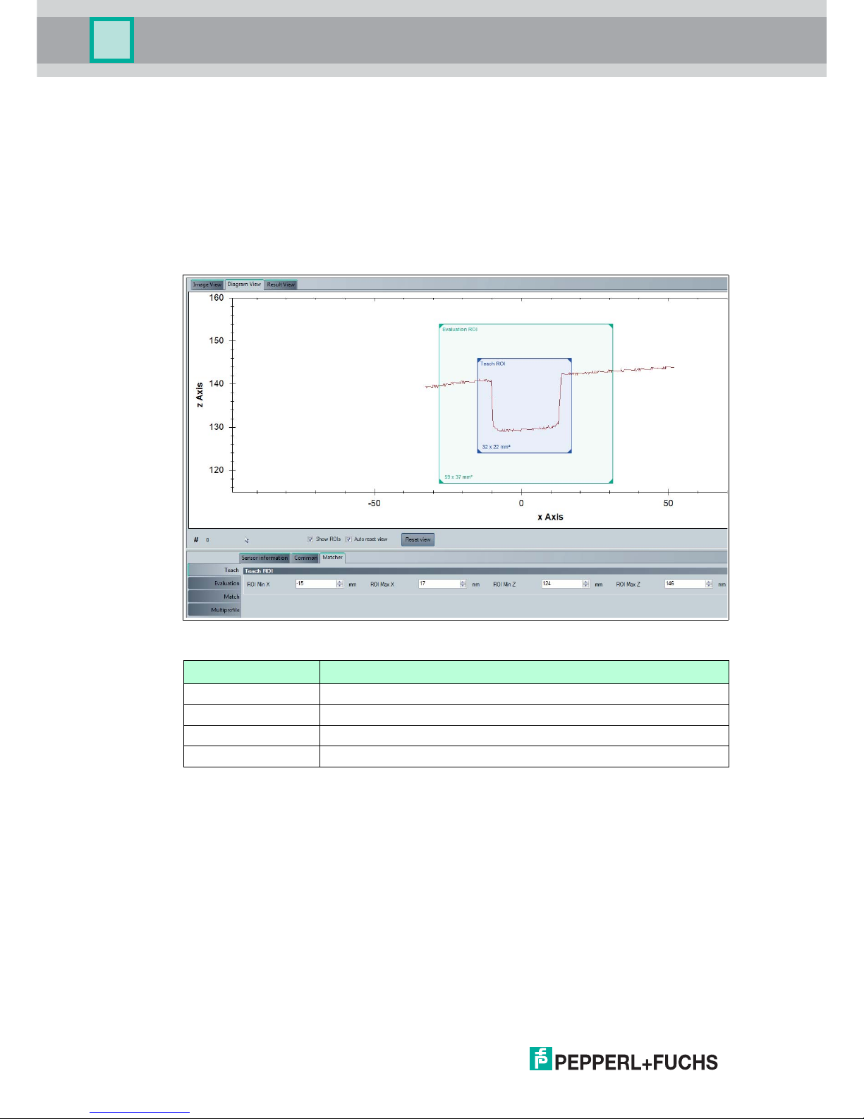
Teach menu item
You can adjust the teach-in range of the sensor under the Teach menu item. The teach-in
range allows you to restrict the range of the reference height profile. The required "Teach ROI"
teach-in range is adjusted using the line profile under the "Diagram View" tab. The coordinates
of the x and z axis are shown in the display field below the graphic.
Figure 5.21 Teach menu item
Designation Function
ROI Min X the smallest value on the x axis
ROI Max X the largest value on the x axis
ROI Min Z the smallest value on the z axis
ROI Max Z the largest value on the z axis
Page 37

SmartRunner Matcher*
Vision Configurator Software
2018-01
37
Evaluation Menu Item
You can adjust the sensor's evaluation range under the Evaluation menu item. The evaluation
range is the range in which the sensor seeks out the taught-in height profile. The required
"Evaluation ROI" evaluation range is adjusted using the line profile under the "Diagram View"
tab. The coordinates of the x and z axis are shown in the display field below the graphic.
Figure 5.22 Evaluation Menu Item
Designation Function
ROI Min X the smallest value on the x axis
ROI Max X the largest value on the x axis
ROI Min Z the smallest value on the z axis
ROI Max Z the largest value on the z axis
Note!
Setting the Frame Size
Moving the teach-in range and evaluation range
This gives you the option to move the teach-in range and evaluation range. To do this, click
with the left mouse button in the teach-in range or evaluation range. The frame of the selected
area is shown as a dashed line. Hold down the mouse button and the window moves as you
move the mouse. Release the mouse button at the position where you want to place the
window. The coordinates in the display field are updated automatically.
Minimizing/maximizing the teach-in range and evaluation range
This gives you the option to broaden or narrow the teach-in range and evaluation range or to
decrease or increase the height. Move the mouse to any edge of the frame until the mouse
cursor changes. This turns into an arrow with 2 ends. When the mouse cursor has changed,
click and hold with the left mouse button and move the mouse until the window is the desired
width and/or height. The size can be changed on all 4 edges, and at the corners, too. The
mouse cursor changes to a diagonal double arrow at the corners and changes the height and
width in the same ratio. The coordinates in the display field are updated automatically.
Page 38

2018-01
38
SmartRunner Matcher*
Vision Configurator Software
Match Menu Item
You can adjust the x and z tolerance range for the sensor under the Match menu item. The
tolerance range determines by how much the height profile may move within the evaluation
range and still be recognized.
Figure 5.23 Match Menu Item
Designation Function
Object contrast Contrast threshold used to detect the laser line on the object.
Tolerance object "Tolerance object" is used to input the width of the envelope curve
around the taught-in object in 0.1 mm increments. The envelope curve
is the basis for the quality parameters. The width of the envelope
curve should be selected so that all good part profiles are located
within the envelope curve despite height profile deviations.
Tolerance X Maximum permitted displacement of the object within the evaluation
range in the X direction.
Tolerance Z Maximum permitted displacement of the object within the evaluation
range in the Z direction.
Quality Good Quality threshold that distinguishes good parts from bad parts.
Quality Variation Quality threshold that distinguishes good parts from bad parts.
Quality Outliers Quality threshold that distinguishes good parts from bad parts.
Note!
More information about the Quality parameters can be found in the chapter on image display
under Result View (see chapter 5.6).
Page 39

SmartRunner Matcher*
Vision Configurator Software
2018-01
39
Multiprofile menu item
The following description only applies to the "VLM350-F280-R4-1001 and VLM350-F280-R41101". You can save different profiles under the Multiprofile menu item. The stored profiles
can be retrieved at any time. You have the option to create up to 32 different profiles. This
means you are in a position to respond quickly and flexibly in the case of frequent adjustments
to production in particular.
Figure 5.24 Multiprofile menu item
The information window consists of 5 columns and 3 buttons. These are explained in more
detail in the following table:
Information window
Designation Function
Active The activated profile is marked by a green arrow. A profile is activated
using the Active selected parameter set button. For this purpose,
the desired profile is selected by clicking with the right mouse cursor
and activated using the Active selected parameter set button.
State The status light changes from yellow to green as soon as a new profile
is created and confirmed using the Rename/Save selected
parameter set button.
Number Profile number
Name The profile name is modified using the Rename/Save selected
parameter set button. Enter the required profile name in the
Parameter set name input field and confirm with OK.
Information Information about the profile can be entered in the information field.
The information is entered using the Rename/Save selected
parameter set button. Enter the required information in the
Parameter set information input field and confirm with OK .
Page 40

2018-01
40
SmartRunner Matcher*
Vision Configurator Software
Save Parameter Settings
The following description only applies to the "VLM350-F280-R4-1001 and VLM350-F280-R41101". The Save job function is used to save parameter data to a read/write tag. This makes it
possible to save settings for different profiles on a read/write tag. You have the option to load
the saved parameters at any time on your sensor. 3 different file types are available to save the
parameters on a read/write tag.
The file types have the following properties:
Figure 5.25 Save Parameter Settings
Position Designation Function
1 Pepperl+Fuchs Config Files
(*.SMARTRUNNER_pfc)
Saves all parameter settings including
communication parameters for 1 profile
2 Pepperl+Fuchs Parameter Set
(*.SMARTRUNNER_pfs)
Saves all parameter settings without
communication parameters for 1 profile
3 Pepperl+Fuchs Complete
Parameter Set
(*.SMARTRUNNER_pfa)
Saves all parameter settings without
communication parameters for 32 profiles
1
3
2
Note!
A parameter file stored on the read/write tag can only be opened using the Vision
Configurator software.
Note!
Please note that the transferred parameter files overwrite the current parameters on the Vision
Configurator software. This can lead to data being lost.
Page 41

SmartRunner Matcher*
Operation
2018-01
41
6Operation
The light section sensor is factory pre-configured to a specific application. As a result, it does
not deliver raw data that needs to be evaluated first, but switching signals that are simple to
process. The sensor only needs to be mounted, connected, and parameterized using teach-in.
The sensor has 4 different operating modes, which can be activated for settings, presentation,
or normal operation.
The following provides more detailed information about the operating modes.
6.1 Configuration Mode
Configuration protocol in configuration mode
To adjust the sensor, it must be in configuration mode.
The command to put the sensor in this mode is 0xA8 0x57. After successfully changing mode,
the sensor responds with an Acknowledge (0x81 0xAC 0x00 0x2D). After an error when
converting the configuration, the sensor responds with a No Acknowledge (0x81 0x53 0xXX
0xYY, where XX = error code and YY = checksum). To check whether the sensor is in
configuration mode, the command Is_In_Config_Mode (0x00 0xFE 0xFE) can be sent. If the
sensor is in configuration mode, it responds with an Acknowledge. Otherwise there is no
response.
Error codes with "No Acknowledge":
0x00 = everything OK
0x01 = checksum incorrect
0x04 = parameter has a different length than that transferred
0x05 = internal error
0x06 = parameter index is unknown
0x07 = read/write access, although not allowed
0x09 = parameter value range is violated
0x0B = other error
0x0E = configuration command too long/short
In this mode, messages are sent according to the extended protocol:
Byte/bit 7 6 5 4 3 2 1 0
1 R/W Length6 Length5 Length4 Length3 Length2 Length1 Length0
2 Index7 Index6 Index5 Index4 Index3 Index2 Index1 Index0
3 Data 1.7 Data 1.6 Data 1.5 Data 1.4 Data 1.3 Data 1.2 Data 1.1 Data 1.0
... ... ... ... ... ... ... ... ...
n Data (n-
2).7
Data (n-
2).6
Data (n-
2).5
Data (n-
2).4
Data (n-
2).3
Data (n-
2).2
Data (n-
2).1
Data (n-
2).0
n+1 xor
B1.7...B(
n).7
xor
B1.6...B(
n).6
xor
B1.5...B(
n).5
xor
B1.4...B(
n).4
xor
B1.3...B(
n).3
xor
B1.2...B(
n).2
xor
B1.1...B(
n).1
xor
B1.0...B(
n).0
Table 6.1 R/W:
0: write
1: read/command
Length: row data length (Data1 ... Data(n-2) )
Page 42

2018-01
42
SmartRunner Matcher*
Operation
Description of Messages
Index Parameter name
Data
Length/bytes
Read/write Description
0xA8 GotoParamMode 0 W Puts the sensor in Configuration
mode
0x01 VendorName Variable R String containing "Pepperl+Fuchs"
0x02 VendorHomepage Variable R String containing the Pepperl+Fuchs
homepage
0x03 ProductName Variable R String containing the product name
0x07 SoftwareVersionDSPVariable R String containing the version
information
0xFE InParamMode 0 R Queries whether the sensor is in
parameterization mode
0xFF LeaveParamMode 0 W Request to exit parameterization
mode
0x20 Interface_Address 1 R/W Set the bus address, value range 0 –
3
0x23 Interface Baudrate 4 R/W Baud rate int32 little-endian in baud
(9600 - 230400)
0x25 Termination
enable
1 R/W Enable/disable termination of the RS-
485 bus
0x68 Laser exposure
time
4 R/W Sets the exposure time in µs
increments
0x10 Flash time 4 R/W Sets the exposure time (LED lighting)
in µs
0xFD Presentation
mode
4 R/W Presentation mode on [0] or off [1]
0x6D Go to teach mode 0 W Puts the sensor in teach-in mode
0xC8 ROI Evaluation 16 R/W "Region of interest" evaluation, 4
bytes in each case: X
min
, X
max
, Z
min
,
Z
max
in mm
0xC9 ROI Teach 16 R/W "Region of interest" for teach-in, 4
bytes in each case: X
min
, X
max
, Z
min
,
Z
max
in mm
0xAD Quality Good 4 R/W Threshold for the part of the contour
that must be within the variation, in %
[0 – 100]
0xAE Quality Variation 4 R/W Threshold for the average deviation
from the taught-in curve, in % [0 –
100]
0xAF Quality Outliers 4 R/W Gage for assessing the quality of the
curve, in % [0 – 100]. The value
worsens if parts of the curve are
detected as being outside the
envelope
0x51 Autotrigger 4 R/W Activates the autotrigger function.
With auto trigger, the sensor triggers
itself cyclically
00 = off
01 = on
0x9F Object contrast 4 R/W Threshold used for detecting the
laser line, in % [0 – 100]
Page 43

SmartRunner Matcher*
Operation
2018-01
43
Save settings
01 F3 10 E2
Saves the current settings in the flash memory
Reset
01 F3 02 F0
Returns to default settings.
Load settings
01 F3 00 F2
The current order and the settings are reloaded.
Switch to Profile
1
02 F3 03 XX XOR
XX = profile number (1…32)
Example: profile number [2]: 02 F3 03 02 F0
Trigger Laser
01 64 01 XOR
Triggers an image capture with evaluation
Trigger LED
01 64 02 XOR
Triggers the LEDs
0xCD Tolerance object 1 R/W Envelope around the taught-in profile
in 0.1 mm increments. The envelope
is the basis for the quality parameters
0x29 Tolerance X 4 R/W Maximum permissible deviation of
the object in the X direction relative to
the taught-in position in mm
0x38 Tolerance Z 4 R/W Maximum permissible deviation of
the object in the Z direction relative to
the taught-in position in mm
0x54 Set/Get Profile
name
1
0 – 32 R/W Write/read a name for the current
profile.
0x55
Get Profile index
1
0 R Returns the index of the currently
active profile.
0x56 Set/Get Profile
information
1
255 R/W Set/retrieve profile information.
1.Only with VLM350-F280-R4-1001 and VLM350-F280-R4-1101
Index Parameter name
Data
Length/bytes
Read/write Description
Page 44

2018-01
44
SmartRunner Matcher*
Operation
Note!
All values are transferred in little-endian format. In this case, the smallest value byte is stored at
the starting address or the smallest value component named first.
Read commands always have a length of 0 bytes.
Example!
In this example, the ROI evaluation is set as follows: set the ROI to ±50 mm in the X direction
and to +100 mm to +200 mm in the Z direction.
0x 10 C8 CE FF FF FF 32 00 00 00 64 00 00 00 C8 00 00 00 77
0x10 = data length
0xC8 = index
0xCEFFFFFF = X
min
-50 mm (little-endian, two's complement)
0x32000000 = X
min
+50 mm (little-endian, two's complement)
0x64000000 = Z
min
+100 mm (little-endian, two's complement)
0xC8000000 = Z
min
+200 mm (little-endian, two's complement)
Response telegram:
[TX] -80 C8 48
[RX] -90 C8 CE FF FF FF 32 00 00 00 64 00 00 00 C8 00 00 00 F7
Example!
In this example, the sensor is transferred to Parameter mode to change some settings.
Afterwards it switches to Runtime mode, a profile is taught in, and a comparison is made
between this profile and another profile (object_1 differs greatly from object_2).
[TX] - A8 57 = GotoParamMode
[RX] - 81 AC 00 2D = Acknowledge
[TX] - 00 FE FE = InParamMode
[RX] - 81 AC 00 2D = Acknowledge
[TX] - 80 AD 2D = Read Quality Good
[RX] - 84 AD 50 00 00 00 7F = Quality Good=80 (0x50)
[TX] - 04 AD 55 00 00 00 FF = Write Quality Good=55 (0x55)
[RX] - 81 AC 00 2D = Acknowledge
[TX] - 04 51 00 00 00 00 55 = Write Autotrigger = Off
[RX] - 81 AC 00 2D = Acknowledge
[TX] - 01 F3 10 E2 = Save settings
[RX] - 81 AC 00 2D = Acknowledge
[TX] - 00 FF FF = LeaveParamMode
[RX] - 81 AC 00 2D = Acknowledge
[TX] - 94 6B = Teach (Object_1)
[TX] - D8 27 = Trigger
[TX] - 90 6F = Teach Result
[RX] - 00 00 00 64 00 00 00 64 = Result=Good
[TX] - D8 27 = Trigger (Object_1)
Page 45

SmartRunner Matcher*
Operation
2018-01
45
[TX] - 84 7B = Result Data
[RX] - 00 01 4C 64 64 64 00 00 00 00 29 = Result Data=Good
[TX] - D8 27 = Trigger (Object_2)
[TX] - 84 7B = Result Data
[RX] - 02 00 4D 50 4A 51 00 01 00 00 05 = Result Data=Bad
Multiprofile:
[TX] - A8 57 = GotoParamMode
[RX] - 81 AC 00 2D = Acknowledge
[TX] - 02 F3 03 02 F0 = Switch to Profile 2
[RX] - 81 AC 00 2D = Acknowledge
[TX] - 03 54 42 61 72 06 = Set Profile Name to "Bar"
[RX] - 81 AC 00 2D = Acknowledge
[TX] - 13 56 54 68 69 73 20 69 73 20 74 68
65 20 42 61 72 20 6A 6F 62 36
= Set Profile information to "This is
the Bar job"
[RX] - 81 AC 00 2D = Acknowledge
[TX] - 80 55 D5 = Read Profile index
[RX] - 81 55 02 D6 = Job index = 2 (0x02)
[TX] - 04 51 00 00 00 00 55 = Write Autotrigger=Off
[RX] - 81 AC 00 2D = Acknowledge
[TX] - 01 F3 10 E2 = Save settings
[RX] - 81 AC 00 2D = Acknowledge
[TX] - 00 6D 6D = Go to teach mode (Object_2)
[RX] - 81 AC 00 2D = Acknowledge
[TX] - 01 64 01 64 = Write Trigger
[RX] - 81 AC 00 2D = Acknowledge
[TX] - 00 FF FF = LeaveParamMode
[RX] - 81 AC 00 2D = Acknowledge
[TX] - D8 27 = Trigger (Object_2)
[TX] - 84 7B = Result Data
[RX] - 00 02 11 64 64 64 00 00 00 00 77 = Result Data=Good
[TX] - D8 27 = Trigger (Object_2 shifted in X
direction)
[TX] - 84 7B = Result Data
[RX] - 00 02 12 64 63 64 00 06 00 00 75 = Result Data=Good
[TX] - D0 01 01 2F = choose Profile 1
[TX] - D8 27 = Trigger (Object_1)
[TX] - 84 7B = Result Data
[RX] - 00 01 13 64 64 64 00 00 00 00 5D = Result Data=Good
Page 46

2018-01
46
SmartRunner Matcher*
Operation
Description of Quality Parameters
Quality Variation =
Quality Good =
Quality Outliers =
1 Variation
2 Learned curve
3 Current curve
Legend
X
T
Number of values in the taught-in profile curve
Z
T
(x) Distance value of the taught-in profile at position x
Z
s
(x) Distance value of the current profile at position x
v Set variation
X
N
Number of values detected during evaluation, although not present during teach-in
X
B
Number of values that lie outside of the envelope
X
L
Number of values that were present during teach-in, but can no longer be found during
evaluation
2 3
1
Page 47

SmartRunner Matcher*
Operation
2018-01
47
6.2 Code Card Mode
The built-in camera function including LED lighting allows for parameterization using Data
Matrix control codes. The control codes are generated using the "Vision Configurator"
operating software. All sensor parameters can be specified in a Data Matrix control code. For
this purpose, the Data Matrix control code is placed in front of the camera. The control code is
registered immediately and decoded. The sensor automatically activates the parameters
contained within. So a large number of sensors can be put into operation easily and quickly.
Generating a control code
1. In the menu bar, select Administration > Create reader programming code.
2. In the Device type section, select sensor type SMARTRUNNER.
3. Select the required parameters in the Select function section.
The control code is displayed in different sizes in the Control Code section.
4. To print the control code, click Print or Print preview.
To save the control code, click Save image.
Figure 6.1 Generating a control code
Tip
It is also possible to generate control codes when no sensor is connected to Vision
Configurator. In this case, you can, for example, generate a control code to assign a particular
IP address to a sensor and then establish a connection with a PC.
Page 48

2018-01
48
SmartRunner Matcher*
Operation
6.2.1 Setting Device Parameters via Control Code
Use Vision Configurator to generate control codes.
Enabling Code Card Mode
Hold down the 2 button on the back of the sensor for more than 2 seconds. Then release the
button.
The Ready LED flashes rapidly and the sensor's camera system begins to flash.
Setting Parameters
1. To assign a parameter, position the relevant control code in the sensor's field of view.
If a valid code is detected, the Result LED lights up green briefly
If an invalid code is detected, the Result LED lights up red briefly
2. The modified parameter is now saved in the sensor's volatile memory. The "Save settings"
control code saves the parameter in the non-volatile memory if necessary.
Disabling Code Card Mode
Press the 2 button on the back of the sensor.
The Ready LED stops flashing and the camera system stops flashing.
Note!
Parameterization mode can be activated only within 10 minutes of the sensor being switched
on.
Page 49

SmartRunner Matcher*
Operation
2018-01
49
6.3 Presentation Mode
You can demonstrate or test the sensor in Presentation mode without the assistance of a PC.
Furthermore, the control buttons are activated/deactivated.
Setting Presentation Mode
1. Connect the sensor to a power supply.
2. Align the sensor to the measurement object.
3. Teach in the measurement object by tapping button 2 on the sensor.
Figure 6.2 Result LED
The result LED lights up red.
4. Press button 1.
The trigger is activated. The result LED lights up green. The measurement object is
taught in.
The result LED lights up red if the profile contour deviates.
Note!
If the autotrigger is activated in the Vision Configurator operating software, you just need to
press button 2 to teach in the measurement object. If the autotrigger is deactivated, the trigger
must be activated by pressing button 1 once the measurement object has been taught in.
Page 50

2018-01
50
SmartRunner Matcher*
Operation
6.4 Runtime Mode
The Runtime mode is the main mode in which the measuring process operates as configured
in the operating software.
6.4.1 Communication via the RS-485 Interface
The control panel and reader communicate via the RS-485 interface during operation. Make
sure that the basic communication settings have been made on the reader, such as setting the
reader address and baud rate.
A distinction is made between request telegrams that the control panel sends to the reader and
response telegrams that the reader sends to the control panel. Each byte of a request or
response telegram consists of 9 bits (8 data bits + 1 parity bit).
Parity Bit
A bit assigned to a binary string used to detect errors. It is added in such a way that the sum
modulo 2 of all bits that are regarded as binary digits in the string, including the parity bit, is
either 0 or 1 depending on the requirement; additional bit that is added to each string or each
byte for control purposes so that the sum of all bits containing binary 1 in the characters or
bytes including control bit results in an odd or even value.
Request Telegram
A request telegram always consists of 2 bytes. The 2nd byte corresponds to the 1st byte;
however, the 8 data bits of the 1st byte are inverted.
Structure of a Request Telegram
Meaning of bits:
R/W: 0 = response, 1 = request
Meaning of Bits
Bit 7 Bit 6 Bit 5 Bit 4 Bit 3 Bit 2 Bit 1 Bit 0
Byte 1 R/W Req. bit 4Req. bit 3Req. bit 2Req. bit 1Req. bit 0A1 A0
Byte 2 ~R/W ~Req. bit 4~Req. bit 3~Req. bit 2~Req. bit 1~Req. bit 0~A1 ~A0
7 6 5 4 3 2 1 0 <- Bit
FunctionR/W R.4 R.3 R.2 R.1 R.0 A.1 A.0 Value
0 x x x x x x x Answer
1 x x x x x x x Request
1 x x x x x 0 0 Read head address 0
1 x x x x x 0 1 Read head address 1
1 x x x x x 1 0 Read head address 2
1 x x x x x 1 1 Reader address 3
1 0 0 0 0 0 x x 0x80 Status (is alive)
1 0 0 0 0 1 x x 0x84 Result data
1 0 0 1 0 0 x x 0x90 Teach result
1 0 1 0 1 0 x x 0xA8 Enable Configuration Mode
1 0 0 1 0 1 x x 0x94 Enable Teach Mode
1 1 0 1 1 0 x x 0xD8 Generate a software trigger
1 1 0 1 0 0 x x 0xD0
Choose Profile
1
Page 51

SmartRunner Matcher*
Operation
2018-01
51
Response Telegram
Status (is alive)
The status always returns 0x55 if the sensor is ready for operation.
Result Protocol
Result Data provides the measurement status and result as a response.
Legend
1.Only with VLM350-F280-R4-1001 and VLM350-F280-R4-1101
7 6 5 4 3 2 1 0
Byte R/W R.4 R.3 R.2 R.1 R.0 A.1 A.0
1 0 1 0 1 0 1 0 1
Byte Bit 7 Bit 6 Bit 5 Bit 4 Bit 3 Bit 2 Bit 1 Bit 0
Byte 1 Status
0 - Addr 1 Addr 0 Event WRN No
Match
ERR
Byte 2 Result
0 R6 R5 R4 R3 R2 R1 R0
Byte 3 Counter
0 C06 C05 C04 C03 C02 C01 C00
Byte 4 Quality
0 Q06 Q05 Q04 Q03 Q02 Q01 Q00
Byte 5 Quality
0 Q16 Q15 Q14 Q13 Q12 Q11 Q10
Byte 6 Quality
0 Q26 Q25 Q24 Q23 Q22 Q21 Q20
Byte 7 PosX
0 PosX13 PosX12 PosX11 PosX10 PosX09 PosX08 PosX07
Byte 8 PosX
0 PosX06 PosX05 PosX04 PosX03 PosX02 PosX01 PosX00
Byte 9 PosZ
0 PosZ13 PosZ12 PosZ11 PosZ10 PosZ09 PosZ08 PosZ07
Byte 10 PosZ
0 PosZ06 PosZ05 PosZ04 PosZ03 PosZ02 PosZ01 PosZ00
Byte 9 Checksum
0 xor xor xor xor xor xor xor
Status Addr Device address
Event Event occurred (future)
Currently read as 0
WRN Unused
No Match Profile does not match the
saved profile
ERR System error or evaluation
error
Result R0 ... R6 Profile number 1 ... 32
0x00 = no object found
Page 52

2018-01
52
SmartRunner Matcher*
Operation
Teach Result Protocol
Teach Result Data returns the status and result of the teach-in process as a response.
Legend
Quality Q00 ... Q26 Quality of the current profile (0
= no profile found, 100 =
perfect match)
Quality: Quality Good
Quality2: Quality Variation
Quality3: Quality Outliers
Counter Increments for each
evaluation, is restarted at
0x3F
Position Data
1
PosX16 ... PosX00 X-deviation of current profile
to saved profile
PosZ16 ... PosZ00 Z-deviation of current profile
to saved profile
1.Only with VLM350-F280-R4-1001 and VLM350-F280-R4-1101
Byte Bit 7 Bit 6 Bit 5 Bit 4 Bit 3 Bit 2 Bit 1 Bit 0
Byte 1 - Status 0 - Addr 1 Addr 0 Event WRN 0 ERR
Byte 2 - Result 0 0 0 0 0 0 0 0
Byte 3 - Counter 0 C06 C05 C04 C03 C02 C01 C00
Byte 4 - Quality A 0 QA6 QA5 QA4 QA3 QA2 QA1 QA0
Byte 5 - Quality B 0 QB6 QB5 QB4 QB3 QB2 QB1 QB0
Byte 6 - Quality C 0 QC6 QC5 QC4 QC3 QC2 QC1 QC0
Byte 7 - Quality D 0 QD6 QD5 QD4 QD3 QD2 QD1 QD0
Byte 8 Checksum
0 xor xor xor xor xor xor xor
Status Addr Device address
Event Event has occurred - for future
use, currently read as 0
WRN Unused
ERR System error or evaluation
error
Result R0 For extended protocol
Always 0
Counter C00 ... C06 Increments with each teach-in
Quality A The quality of the current
teach-in
0 = teach-in not possible
100 = perfect teach-in
Quality B-D Unused
Page 53

SmartRunner Matcher*
Operation
2018-01
53
Software Trigger
After sending the sequence for the software trigger, the sensor triggers an image capture. No
response telegram is generated to the command.
Teach-In
After transmitting the command to start the teach-in (0x94), the sensor begins the teach-in
routine. A trigger must subsequently be transmitted.
Choose profile
1
Legend
1.Only with VLM350-F280-R4-1001 and VLM350-F280-R4-1101
Byte Bit 7 Bit 6 Bit 5 Bit 4 Bit 3 Bit 2 Bit 1 Bit 0
Byte 1 Request
1 1 0 1 0 0 Address1Address
0
Byte 2 Data
length
0 0 0 0 0 0 0 1
Byte 3 Data
0 6 P5 P4 P3 P2 P1 P0
Byte 4 Checksum
~xor ~xor ~xor ~xor ~xor ~xor ~xor ~xor
Request Bit 7 ... 2 Command ID
Address Address of the current device
Data Bit 7 0
Bit 6 0
P5 ... P0 1 ... 32: Profile number
0... : not defined
> 32: not defined
Page 54

2018-01
54
SmartRunner Matcher*
Maintenance and Repair
7 Maintenance and Repair
7.1 Maintenance
The device is maintenance-free. To get the best possible performance out of your device, keep
the optical unit on the device clean, and clean it when necessary.
Observe the following instructions when cleaning:
Do not touch the optical unit with your fingers.
Do not immerse the device in water. Do not spray the device with water or other fluids.
Do not use a scouring agent to clean the surface of the device.
Use a cotton or paper cloth moistened with water or isopropyl alcohol (not soaked).
Remove any residual alcohol using a cotton or paper cloth moistened with distilled water
(not soaked).
Wipe the device surfaces dry using a lint-free cloth.
7.2 Repair
The device must not be repaired, changed, or manipulated. In case of failure, always replace
the device with an original device.
Danger!
Risk of death due to electrical current!
Contact with live parts causes immediate risk of death.
Allow only qualified electricians to carry out work on the electrical installation.
Switch off the power supply before carrying out maintenance, cleaning, and repairs, and
prevent the supply from being switched on again.
Keep the live parts free from moisture.
Page 55

SmartRunner Matcher*
Troubleshooting
2018-01
55
8Troubleshooting
8.1 What to Do in Case of a Fault
Before you have the device repaired, take the following actions:
Test the plant according to the checklist below.
Contact our service center to localize the problem.
Checklist
Fault Cause Remedy
"Power" LED
does not light
up
The power supply is switched
off
Check whether there is a reason why the
power supply is switched off (installation or
maintenance work, etc.). Switch on the power
supply if appropriate.
Wiring fault in the splitter or
control cabinet, cable break
Check the wiring carefully and repair any
faults with the wiring. Check the cable to
ensure proper function.
Control panel
receiving no
measurement
data
Connection cable not
connected
Connect the connection cable.
Incorrect connection cable
used
Use the appropriate connection cable only.
Incorrect baud rate set Make sure that you have set the correct baud
rate for the sensor.
Measurement
object not
recognized
Protective cover dirty Clean protective cover.
Reflections Avoid reflections
Foreign exposure Avoid foreign exposure
Exposure time control Set exposure (see chapter 5.7.2)
Teach-in range set incorrectly Set teach-in range (see chapter 5.7.2)
Evaluation range set
incorrectly
Set evaluation range (see chapter 5.7.2)
Tolerance range set
incorrectly
Set tolerance range (see chapter 5.7.2)
Measurement
errors
Surfaces with pronounced
scored structure and reflective
surfaces
Improved arrangement of sensor components
to the measurement object
Temperature change in the
sensor
Allow sensor to warm up for around 15
minutes before the measuring process is
started.
Incorrect distance to the
measuring object
Note distance values
Housing incorrectly mounted Install housing correctly (see chapter 3.3)
Presentation
mode not
working
Presentation mode not
activated
Enable Presentation mode and Autotrigger
and confirm using "Save settings"
No connection
to the sensor
AC voltage or supply voltage
too high
Connect sensor to direct current (DC) only.
Ensure that the level of supply voltage is
within the specified sensor range.
Data Matrix
control code is
not detected
Maximum number of
parameters exceeded
We recommend a maximum of 10 parameters
Page 56

2018-01
56
SmartRunner Matcher*
Troubleshooting
If none of the above remedies the problem, please contact our service center. Please
have the fault patterns and the version number of the firmware available. The firmware
version number can be found at the top right of the user interface.
Page 57

SmartRunner Matcher*
License Note
2018-01
57
9 License Note
The SmartRunner sensor ships with firmware ("software") programmed into it.
This software is based in part on the work of the Independent JPEG Group.
The software is based on works by Texas Instruments Incorporated, which are distributed
under the following licenses:
SYS/BIOS License
Copyright (c) 2012-2015, Texas Instruments Incorporated.
All rights reserved.
Redistribution and use in source and binary forms, with or without modification, are permitted
provided that the following conditions are met:
* Redistributions of source code must retain the above copyright notice, this list of conditions,
and the following disclaimer.
* Redistributions in binary form must reproduce the above copyright notice, this list of
conditions, and the following disclaimer in the documentation and/or other materials provided
with the distribution.
* Neither the name of Texas Instruments Incorporated nor the names of its contributors may be
used to endorse or promote products derived from this software without specific prior written
permission.
THIS SOFTWARE IS PROVIDED BY THE COPYRIGHT HOLDERS AND CONTRIBUTORS
"AS IS" AND ANY EXPRESS OR IMPLIED WARRANTIES, INCLUDING, BUT NOT LIMITED
TO, THE IMPLIED WARRANTIES OF MERCHANTABILITY AND FITNESS FOR A
PARTICULAR PURPOSE ARE DISCLAIMED. IN NO EVENT SHALL THE COPYRIGHT
OWNER OR CONTRIBUTORS BE LIABLE FOR ANY DIRECT, INDIRECT, INCIDENTAL,
SPECIAL, EXEMPLARY, OR CONSEQUENTIAL DAMAGES (INCLUDING, BUT NOT
LIMITED TO, PROCUREMENT OF SUBSTITUTE GOODS OR SERVICES; LOSS OF USE,
DATA, OR PROFITS; OR BUSINESS INTERRUPTION) HOWEVER CAUSED AND ON ANY
THEORY OF LIABILITY, WHETHER IN CONTRACT, STRICT LIABILITY, OR TORT
(INCLUDING NEGLIGENCE OR OTHERWISE) ARISING IN ANY WAY OUT OF THE USE OF
THIS SOFTWARE, EVEN IF ADVISED OF THE POSSIBILITY OF SUCH DAMAGE.
Eclipse Distribution License - v 1.0
Copyright (c) 2007, Eclipse Foundation, Inc. and its licensors.
All rights reserved.
Redistribution and use in source and binary forms, with or without modification, are permitted
provided that the following conditions are met:
Redistributions of source code must retain the above copyright notice, this list of
conditions, and the following disclaimer.
Redistributions in binary form must reproduce the above copyright notice, this list of
conditions, and the following disclaimer in the documentation and/or other materials
provided with the distribution.
Neither the name of the Eclipse Foundation, Inc. nor the names of its contributors may be
used to endorse or promote products derived from this software without specific prior
written permission.
THIS SOFTWARE IS PROVIDED BY THE COPYRIGHT HOLDERS AND CONTRIBUTORS
"AS IS" AND ANY EXPRESS OR IMPLIED WARRANTIES, INCLUDING, BUT NOT LIMITED
TO, THE IMPLIED WARRANTIES OF MERCHANTABILITY AND FITNESS FOR A
PARTICULAR PURPOSE ARE DISCLAIMED. IN NO EVENT SHALL THE COPYRIGHT
OWNER OR CONTRIBUTORS BE LIABLE FOR ANY DIRECT, INDIRECT, INCIDENTAL,
SPECIAL, EXEMPLARY, OR CONSEQUENTIAL DAMAGES (INCLUDING, BUT NOT
Page 58

2018-01
58
SmartRunner Matcher*
License Note
LIMITED TO, PROCUREMENT OF SUBSTITUTE GOODS OR SERVICES; LOSS OF USE,
DATA, OR PROFITS; OR BUSINESS INTERRUPTION) HOWEVER CAUSED AND ON ANY
THEORY OF LIABILITY, WHETHER IN CONTRACT, STRICT LIABILITY, OR TORT
(INCLUDING NEGLIGENCE OR OTHERWISE) ARISING IN ANY WAY OUT OF THE USE OF
THIS SOFTWARE, EVEN IF ADVISED OF THE POSSIBILITY OF SUCH DAMAGE.
Page 59

Subject to modifications
Copyright PEPPERL+FUCHS • Printed in Germany
www.pepperl-fuchs.com
FACTORY AUTOMATION –
SENSING YOUR NEEDS
Worldwide Headquarters
Pepperl+Fuchs GmbH
68307 Mannheim · Germany
Tel. +49 621
776-0
E-mail: info@de.pepperl-fuchs.com
USA Headquarters
Pepperl+Fuchs Inc.
Twinsburg, Ohio
44087 · USA
Tel. +1
330 4253555
E-mail: sales@us.pepperl-fuchs.com
Asia Pacific Headquarters
Pepperl+Fuchs Pte Ltd.
Company Registration
No. 199003130E
Singapore 139942
Tel. +65 67799091
E-mail: sales@sg.pepperl-fuchs.com
/ DOCT-5441C
01/2018
 Loading...