

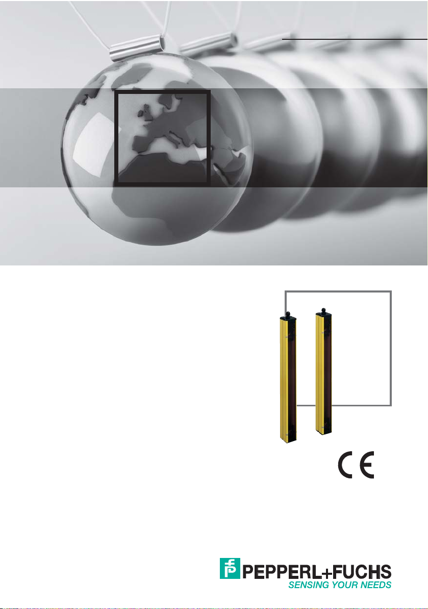
Pepperl+Fuchs SLP8-2-A, SLP10-2-T, SLP8-2-A-L, SLP8-2-M, SLP10-2-R Original Instructions Manual
...
ORIGINAL INSTRUCTIONS
FACTORY AU TOM ATIO N
Safety light grid
SLP series

SLP series safety light grid
The latest version of the General Terms of Supply for Products and Services in the Electronics Industry issued
by the German Electrical and Electronic Manufacturers’ Association (ZVEI) and
the "Extended Retention of Title" clause apply to this document.

SLP series safety light grid
1 Introduction ...............................................................................4
1.1 Congratulations ................................................................................ 4
1.2 Contact .............................................................................................4
1.3 Symbols Used .................................................................................. 4
2 Declaration of Conformity .... .... ... ... ... .... ... ... ... ... .... ... ... ... .... ......5
3 Safety ......................................................................................... 6
3.1 Safety-Relevant Symbols ................................................................. 6
3.2 Intended Use .................................................................................... 6
3.3 Application ........................................................................................ 6
3.4 Mounting .......................................................................................... 7
3.5 Installation ........................................................................................ 7
3.6 Adjustment ....................................................................................... 7
3.7 Displays ............................................................................................ 7
3.7.1 Functional Safety Data .....................................................................8
3.7.2 Conformity with Standards and Directives ........................................8
3.7.3 Approvals and Certificates ................................................................8
3.8 Electrical Connection ....................................................................... 9
3.9 Dimensions .................................................................................... 10
3.10 Ordering Information ...................................................................... 12
4 Deviation Mirror ...................................................................... 13
4.1 Application ...................................................................................... 13
4.2 Technical Data ............................................................................... 13
4.3 Dimensions .................................................................................... 14
4.4 Ordering Information ...................................................................... 14
5 Signal Lamps ........................................................................... 15
5.1 Mounting ........................................................................................ 15
5.2 Technical Data ............................................................................... 15
5.3 Electrical Connection ..................................................................... 16
5.4 Dimensions .................................................................................... 16
5.5 Ordering Information ...................................................................... 16
6 Accessories ..................................... ............................. ........... 17
6.1 Mounting Set .................................................................................. 17
6.2 Test Rod ......................................................................................... 17
6.3 Beam Alignment Aid ....................................................................... 17
6.4 Profile Alignment Aid ...................................................................... 17
7 Testing and Application Checklist ........................................ 18
Issue date 28.05.2018 Part no. 221139
3
SLP series safety light grid
Introduction
1Introduction
1.1 Congratulations
You have decided to purchase a device from Pepperl+Fuchs. Pepperl+Fuchs develops, produces, and
markets electronic sensors and interface modules worldwide for the automation technology market.
Please read the operating instructions carefully before installing this device and putting it into operation. The instructions and notes contained in this document will guide you step by step through the installation and commissioning procedures to ensure trouble-free use of this product. By doing so, you:
• Guarantee safe operation of the device
• Can utilize the entire range of device functions
• Avoid faulty operation and associated faults
• Reduce costs associated with downtime and incidental repairs
• Increase the effectiveness and operating efficiency of your plant.
Store these instructions somewhere safe in order to have them available for future work on the device.
Directly after opening the packaging, please ensure that the device is intact and that the package is
complete.
1.2 Contact
If you have any questions about the device, its functions, or accessories, please contact us at:
Pepperl+Fuchs GmbH
Lilienthalstraße 200
68307 Mannheim, Germany
Tel.: +49 (0)621 776-1111
Fax: +49 (0)621 776-271111
E-mail:fa-info@de.pepperl-fuchs.com
1.3 Symbols used
The following symbols are used in this manual:
Note!
This symbol draws your attention to important information.
Issue date 28.05.2018 Part no. 221139
4

SLP series safety light grid
Declaration of Conformity
2 Declaration of Conformity
All products were developed and manufactured under observance of the applicable European standards and guidelines.
Note!
A Declaration of Conformity may be requested from the manufacturer.
The product manufacturer, Pepperl+Fuchs GmbH, 68307 Mannheim, has a certified quality assurance
system that conforms to ISO 9001.
ISO9001
Issue date 28.05.2018 Part no. 221139
5
SLP series safety light grid
Safety
3Safety
3.1 Safety-Relevant Symbols
Danger!
This symbol warns of an immediate and present danger.
Failure to observe this warning may result in personal injury or even death.
Warning!
This symbol warns of a potential fault or hazard.
Failure to observe this warning may result in personal injury or extensive damage to
property.
Caution!
This symbol warns of a potential fault.
Failure to observe this warning may result in the device and/or any systems and plants
connected to it malfunctioning or giving out completely.
3.2 Intended use
Devices in the SLP...-R series of safety light grids comprise a receiver unit and a corresponding SLP...-T safety light barrier emitter. Together, this unit forms a multi-beam photoelectric protective device. The protection beams are formed between the emitters and
receivers. This system may only be used as intended as an active opto-electronic protective device (AOPD) to protect danger spots and danger areas from being accessed.
If used for any other purpose, the intended function of the system can no longer be guaranteed.
In addition to the notes in these instructions, the safety regulations, standards, and other
regulations concerning the application must be taken into consideration.
3.3 Application
Light grids from the SLP series can be used with 2-, 3-, and 4-beam access protections as
specified in EN ISO 13855. The beam spacings are fixed and meet the specifications outlined in the standard.
SLP light grids consist of an emitter and receiver.
The emitter and receiver for the SPL 8-2-A active column are incorporated into a single
housing. A deviation mirror SLP 8-2-M must be positioned on the opposite side to operate
the device.
A complete safety device includes a compatible control unit that controls the emitter, evaluates the receiver signals, and generates the resulting output signal (OSSD), as well as
an emitter and receiver.
Control units from the SB4... series can be used.
Issue date 28.05.2018 Part no. 221139
6
 Loading...